





For 1998-2010 VW Beetle Trailer Hitch + Wiring 5 Pin Fits All Including Convertible (Except Turbo) Curt 11066 1-1/4 Tow Receiver
Model: 11066 56175 57187 58303-CH3676This Trailer Tow Hitch + 5-Flat Fits The Following Vehicles:
1998 - 2010 Volkswagen Beetle All Including Convertible (Except Turbo)
This Trailer Tow Hitch + 5-Flat Includes the Following Parts:
- Class 1 Trailer Hitch, 1-1/4" Receiver (Drilling Required)
- 3-to-2-Wire Taillight Converter (Requires Splicing)
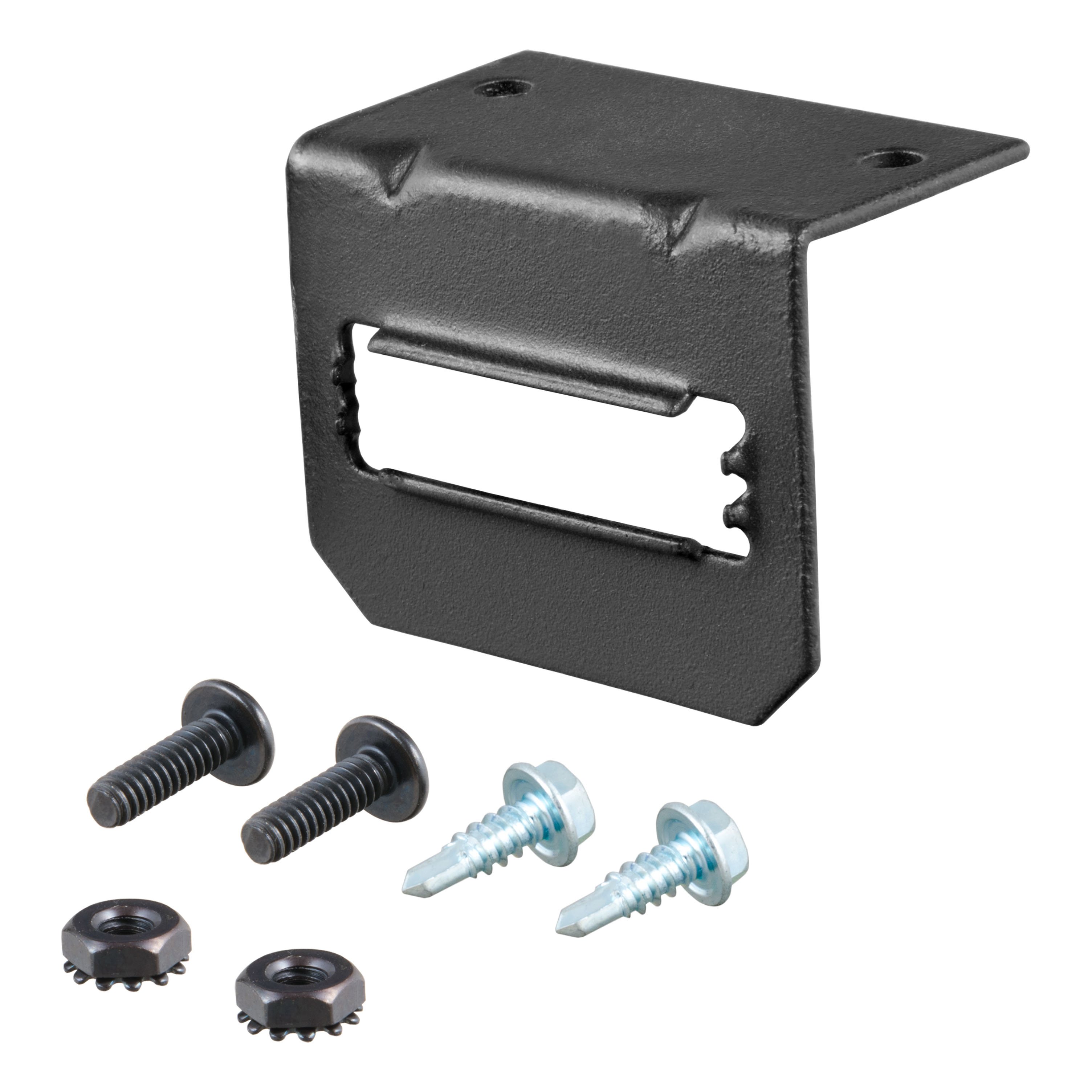
- 4-Way to 5-Way Flat Install Kit for Boat Trailer Surge and Connector Mounting Bracket for 5-Way Flat
- Installation instructions, schematics, diagrams, and hardware (if required).
List of Fitment Years:
1998, 1999, 2000, 2001, 2002, 2003, 2004, 2005, 2006, 2007, 2008, 2009, 2010
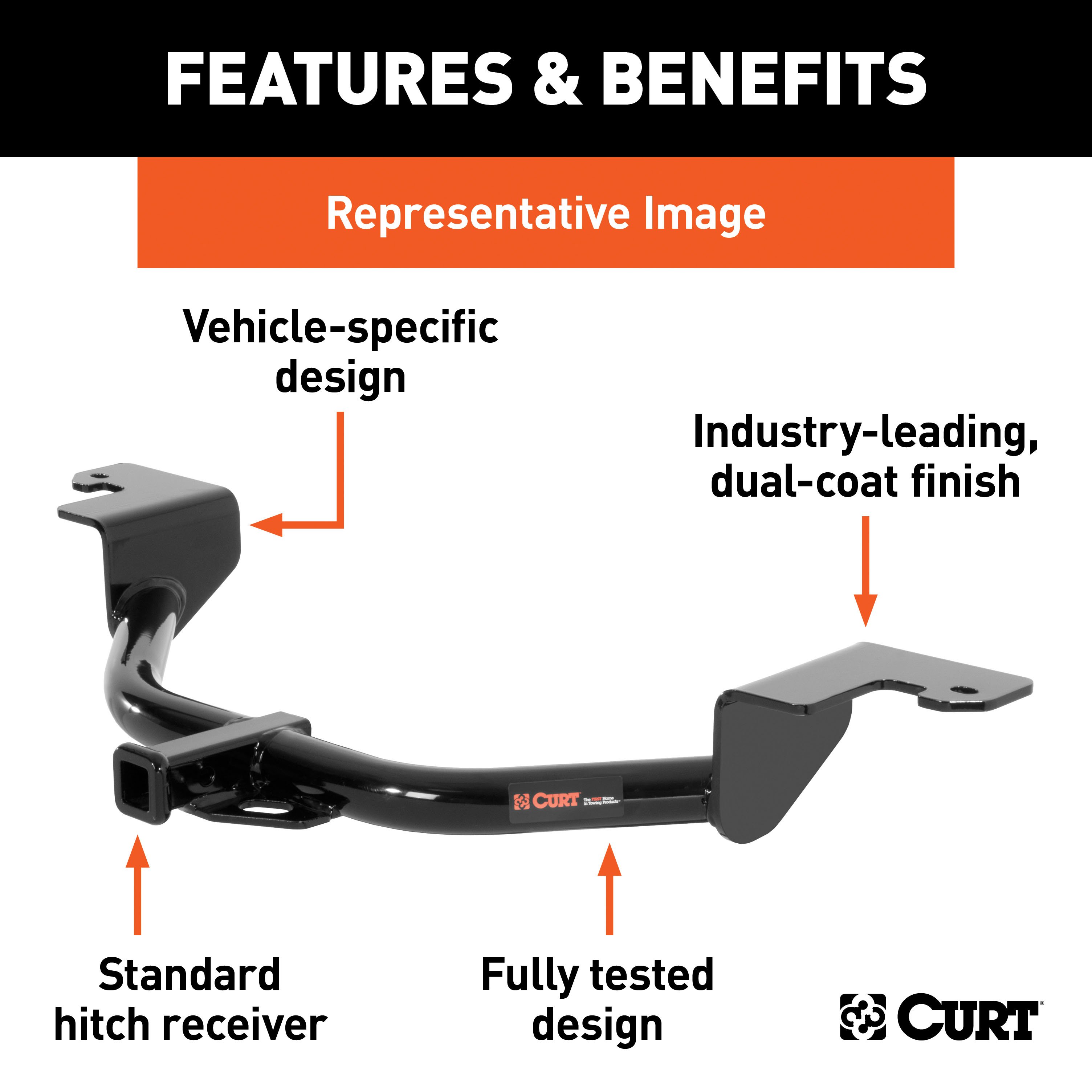
CURT 11066 Class 1 Trailer Hitch, 1-1/4-Inch Receiver
Manufactured by: Curt
However you define adventure -- whether it's climbing onto the back of a mountain bike, hunting from the top of a tree stand or camping with the family a long way from nowhere -- CURT class 1 hitches provide a light-duty towing receiver to help you Bring It Each is made to fit a specific vehicle, providing easier installation, a better fit and optimal towing capacity Custom class 1 trailer hitches are available for a variety of smaller vehicle types, including the compact car, crossover, minivan and small SUV.
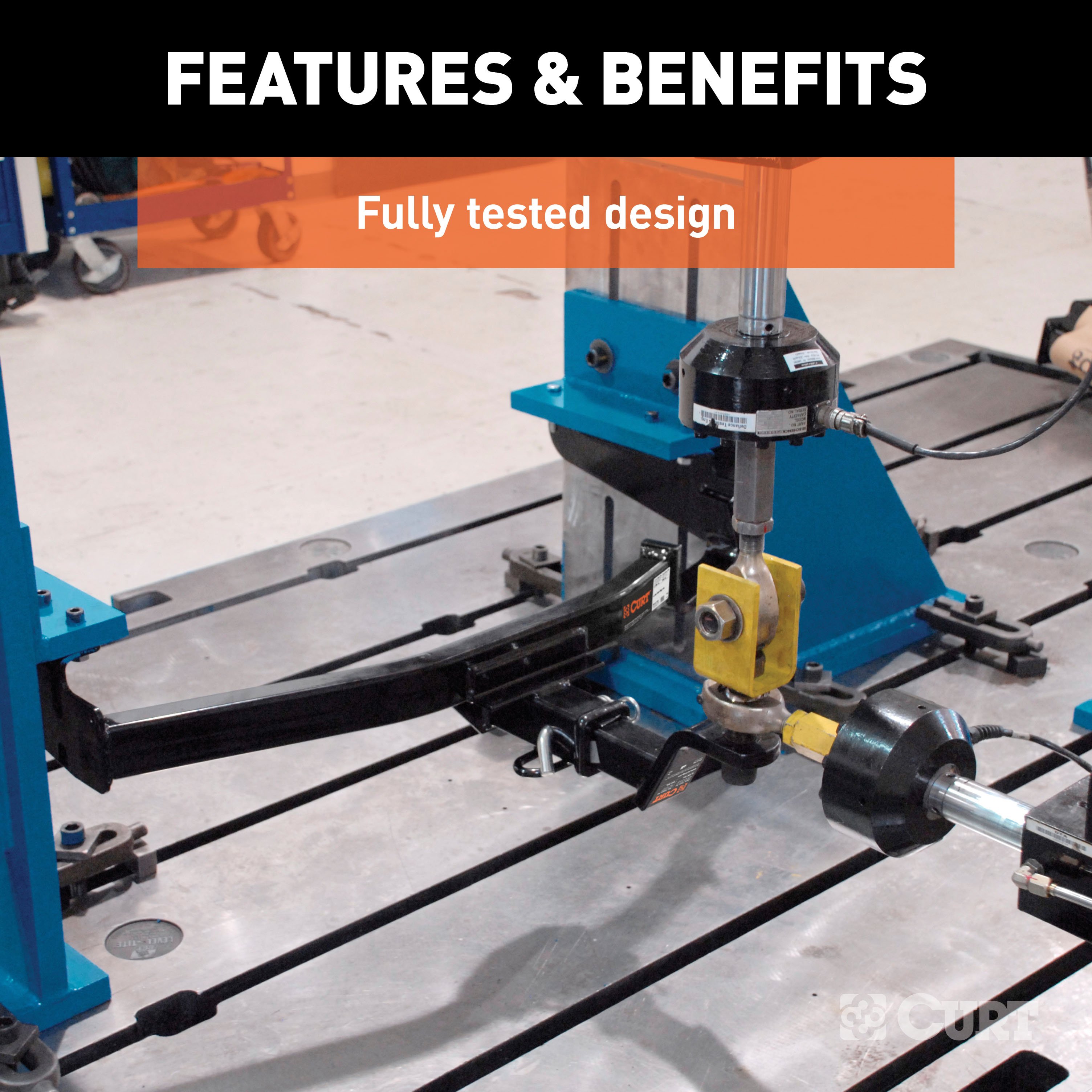
This particular class 1 hitch is designed to be a custom hitch for certain years of the Volkswagen Beetle, Golf and Golf City (to verify vehicle compatibility, see the CURT fitment guide at trailerjacks.com) Tested in accordance with SAE J684, it offers a weight carrying capacity of 2,000 lbs GTW and 200 lbs.
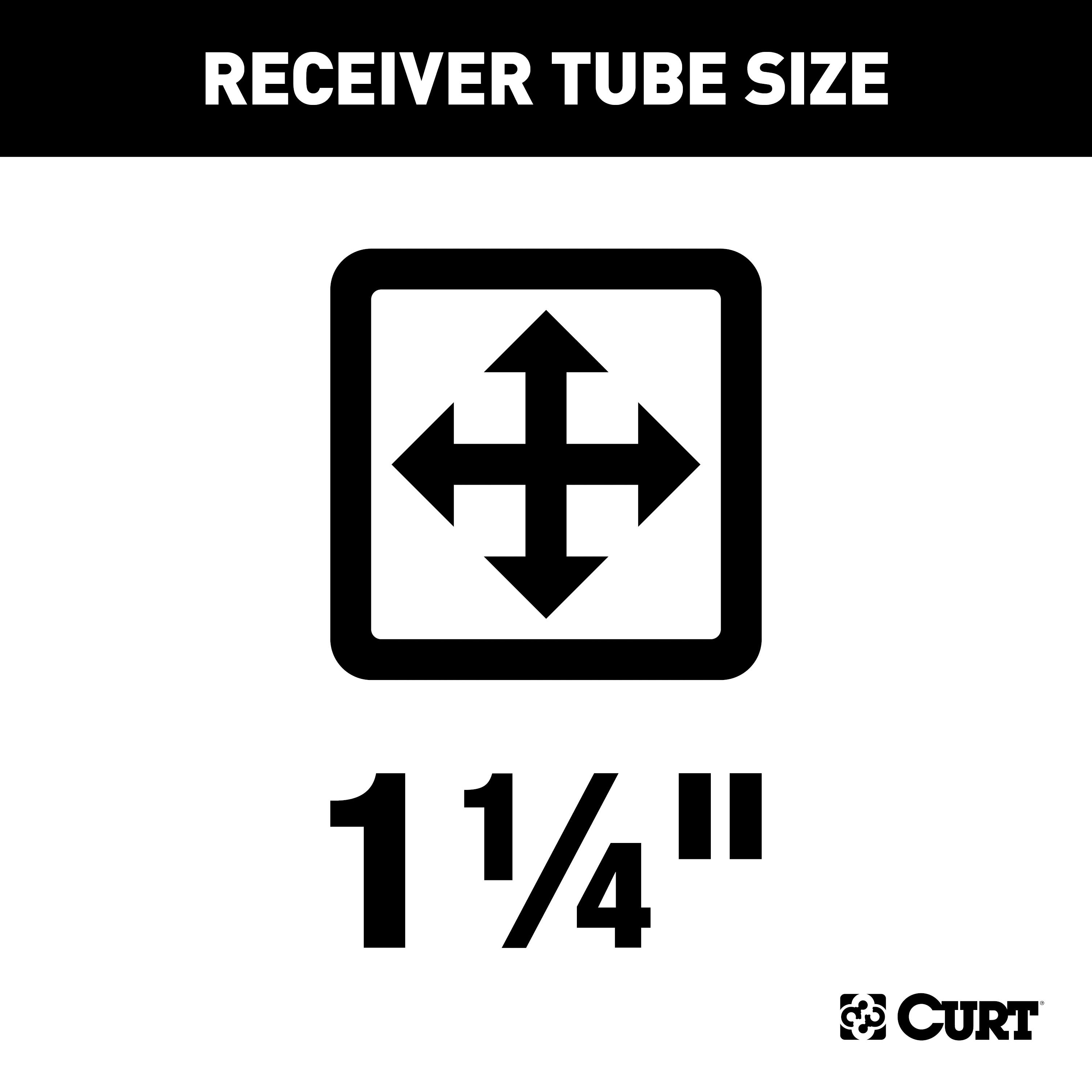
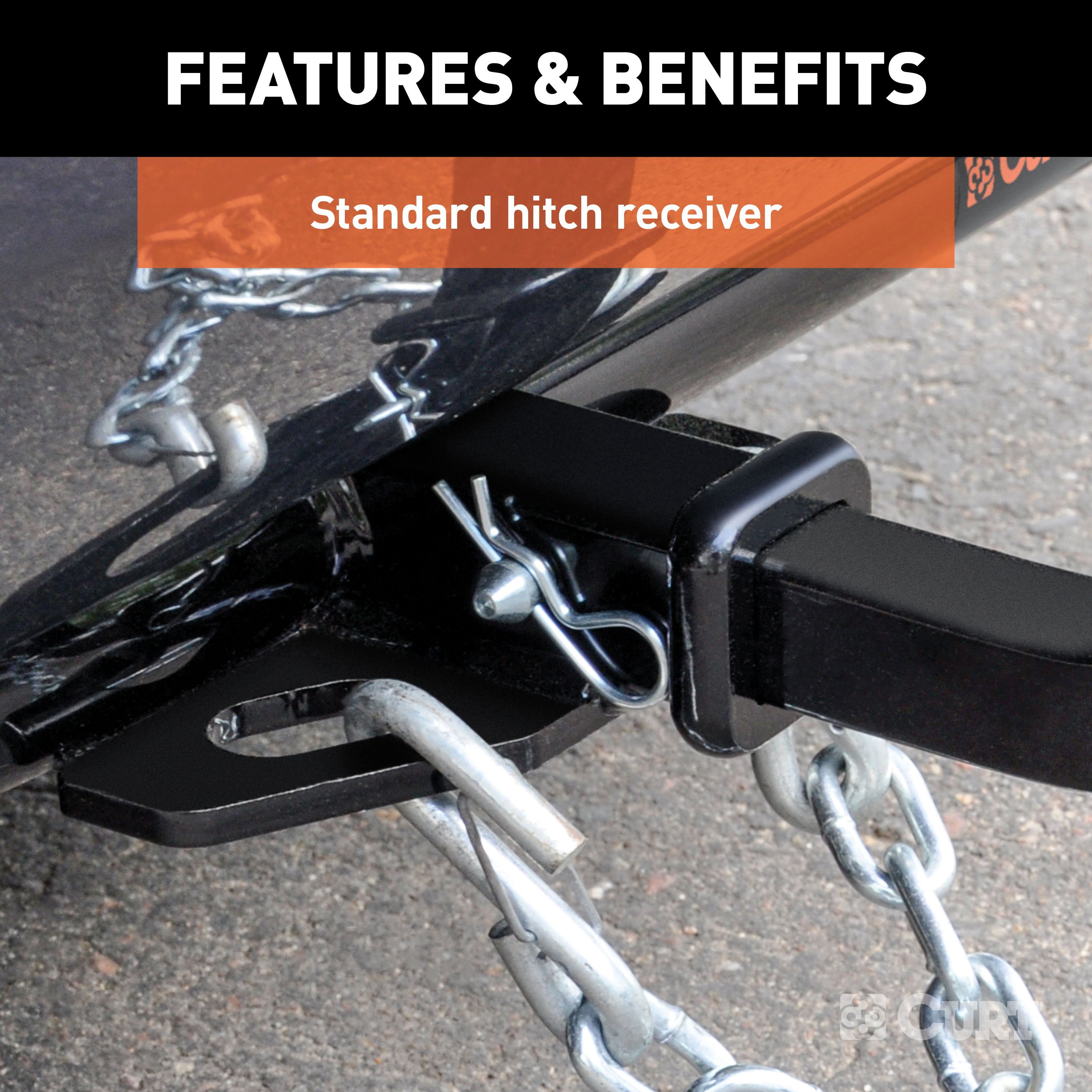
TW It is equipped with 1-1/4" receiver tube opening to accept a ball mount shank or other hitch mount This class 1 hitch also comes with all necessary mounting hardware.
With its lightweight design and smaller receiver tube size, a class 1 hitch is especially useful for adding cargo space with a hitch-mounted bike rack or cargo carrier They can also typically be used to tow small trailers such as a utility trailer, kayak trailer or teardrop camper (never exceed the lowest weight capacity of any towing component; i.e the vehicle, hitch, trailer, etc).
Though CURT class 1 trailer hitches are only intended for light-duty towing, we apply the same principles of quality as we do to the rest of our rear mount hitches Each class 1 hitch is made with hands-on engineering, high-strength steel and precise welding We use a co-cured finish of liquid A-coat, inside and out, and durable black powder coat to provide a lasting defense against rust, chips and UV rays..
Features:
- Rated to 2,000 lbs. gross trailer weight and 200 lbs. tongue weight
- Engineered with a vehicle-specific design for a custom fit
- Tested for safety in accordance with SAE J684
- Precisely welded for superior strength and fit
- Protected by a durable high-gloss black powder coat finish
- Co-cured in a rust-resistant liquid A-coat, inside and out
- Equipped with an open-back receiver for easy cleaning
- Limited lifetime warranty (one-year finish, one-year parts)
- Made in USA (may include imported hardware)
CURT 56175 Non-Powered 3-to-2-Wire Splice-in Tail Light Converter, 4-Pin Wiring Harness
Manufactured by: Curt
When your vehicle does not readily provide an electrical connection for hooking up your trailer, CURT electrical converts offer the solution Working tail lights on your trailer are absolutely essential any time you tow, and a converter provides an effective way to properly equip your vehicle for safe towing A CURT electrical converter, much like our custom vehicle-to-trailer wiring harnesses, provides a trailer connector on your vehicle by splicing into the vehicle's electrical system.
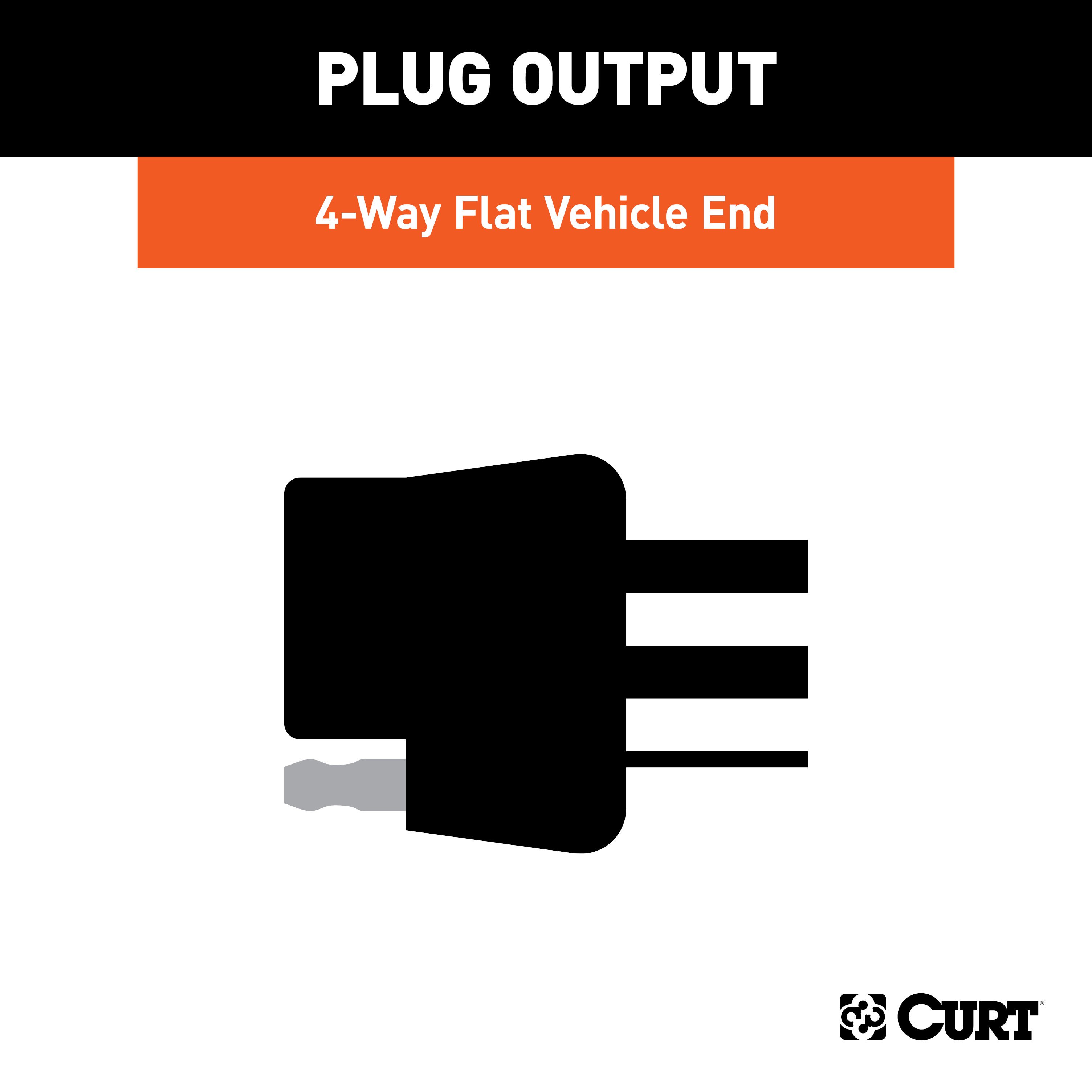
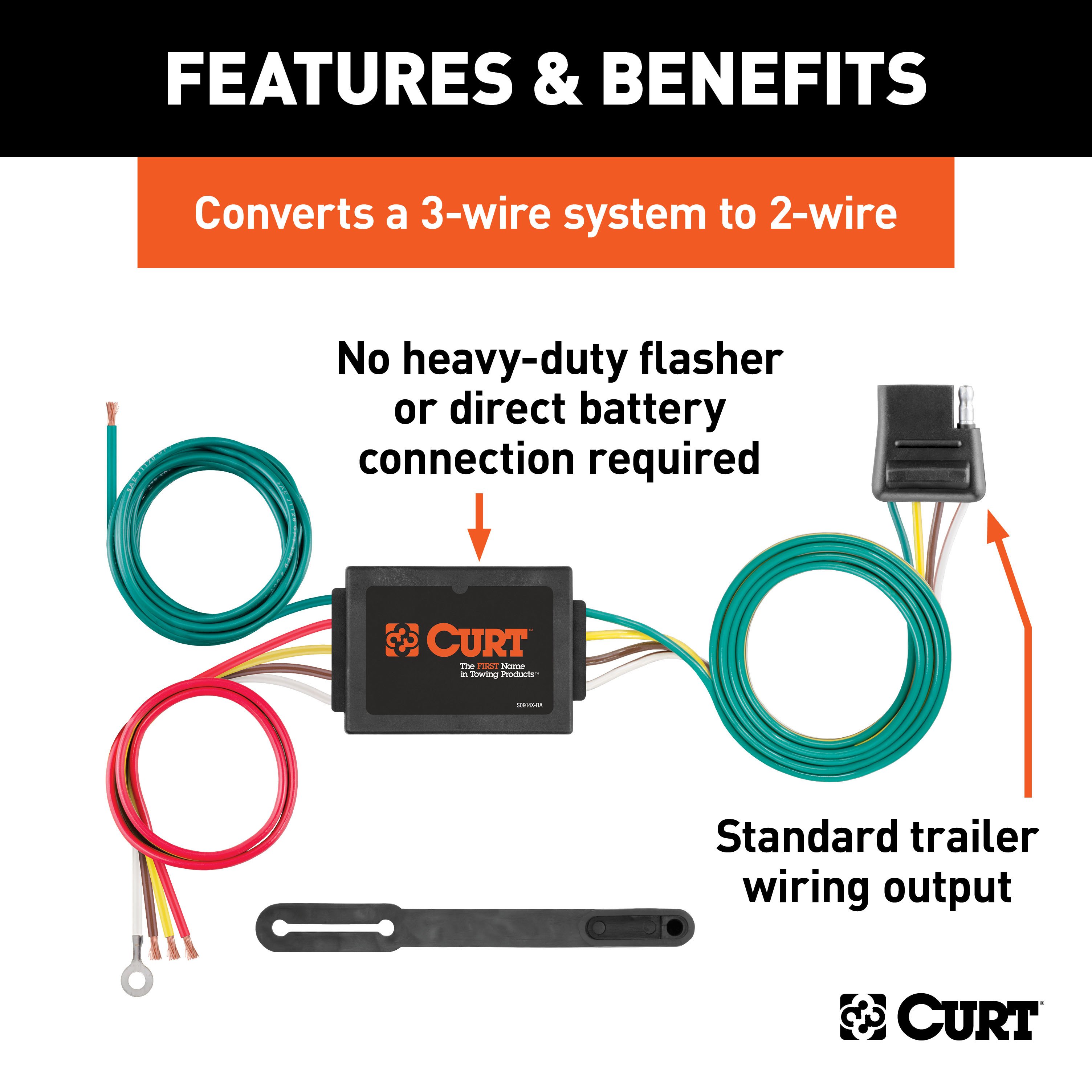
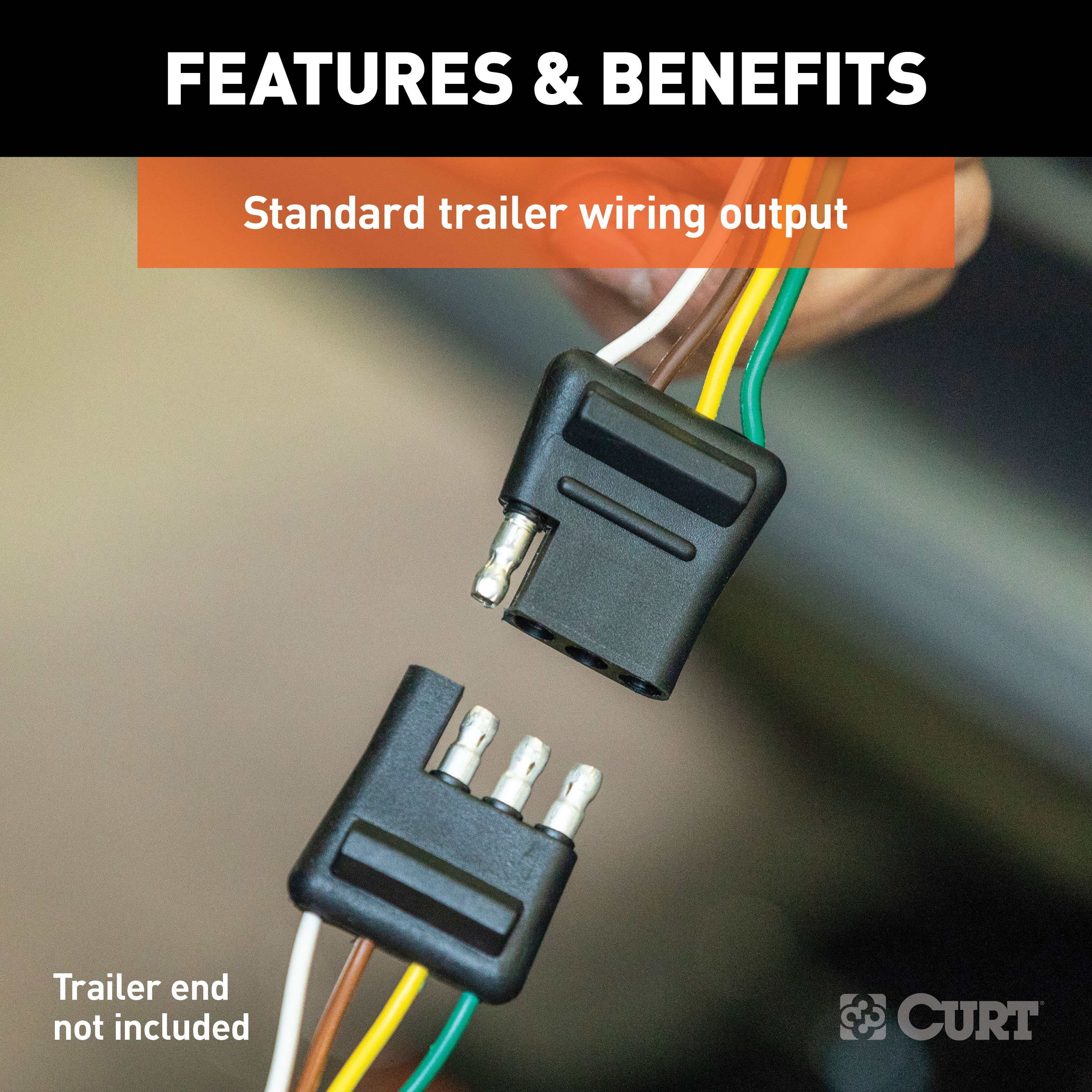
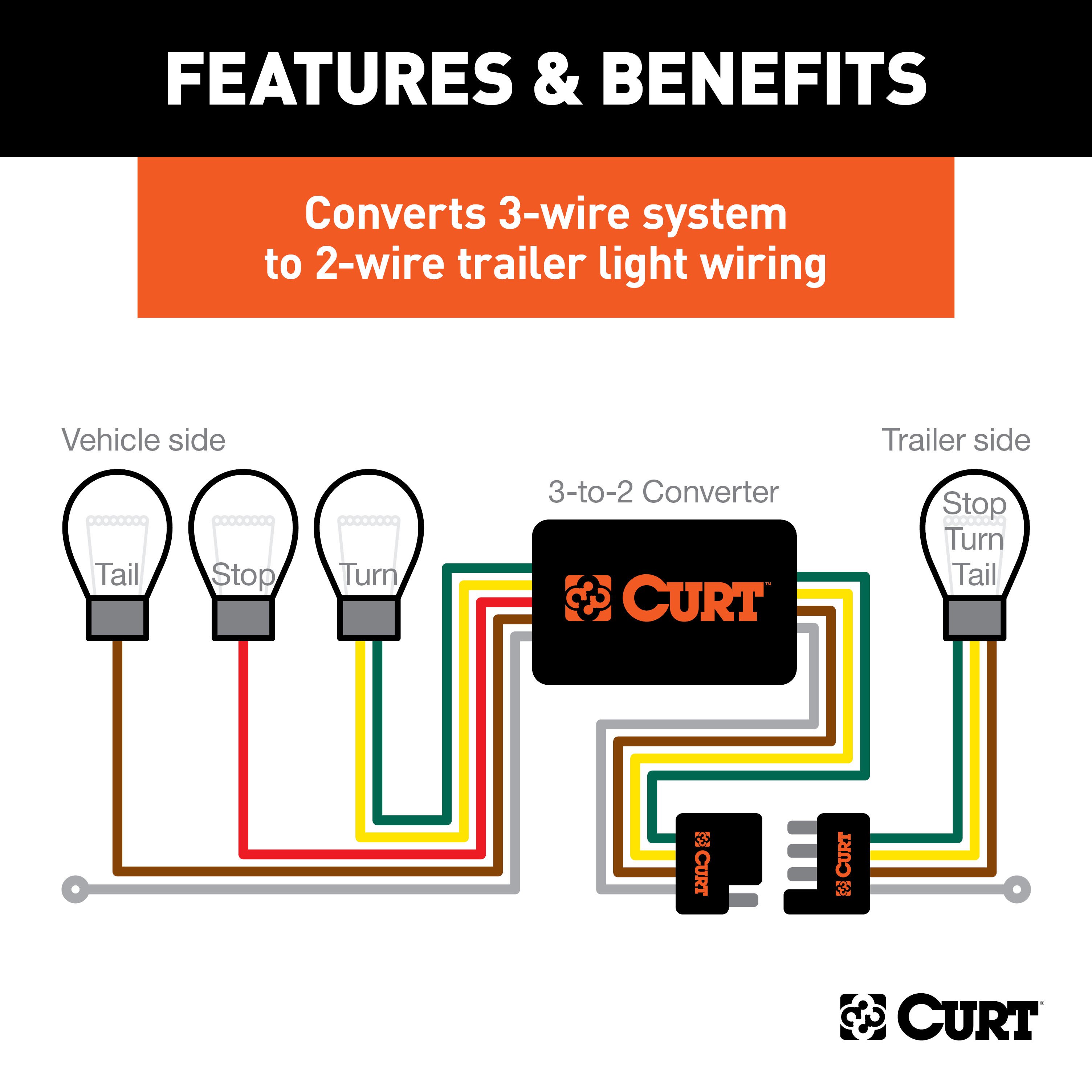
Electrical converters are designed to splice directly into the taillight wiring, rather than plugging into various sockets, giving them the nickname "taillight converters" Though it requires a little extra work compared to a custom wiring harness, a tail light converter offers a reliable, long-term connector solution This CURT electrical converter is designed to convert a 3-wire system to a 2-wire system and provides a standard 4-way flat connector socket to plug in your trailer.
It is designed to fit certain models of Acura, Audi, Buick, Chevrolet, Chrysler, Dodge, Eagle, Ford, Geo, Honda, Hyundai, Infiniti, Isuzu, Kia, Mazda, Mercedes, Mercury, Mitsubishi, Nissan, Oldsmobile, Peugeot, Plymouth, Pontiac, Saturn, Suzuki, Toyota, Volkswagen and Volvo (to verify your vehicle compatibility, see the CURT fitment guide at trailerjacks.com) This converter is made with cutting-edge surface-mount technology (SMT) circuitry, featuring electrical components that are mounted directly to the surface of the board rather than being inserted into a series of holes SMT circuits have longer life cycles, lower resistance, reduced heat generation and are more reliable than through-hole-mounted components..
Features:
- Converts 3-wire vehicle electrical system to standard 2-wire trailer wiring
- 4-way flat output connects tail lights, brake lights and turn signals
- Constructed with SMT circuitry for better performance and durability
- Color-coded wires for easier installation
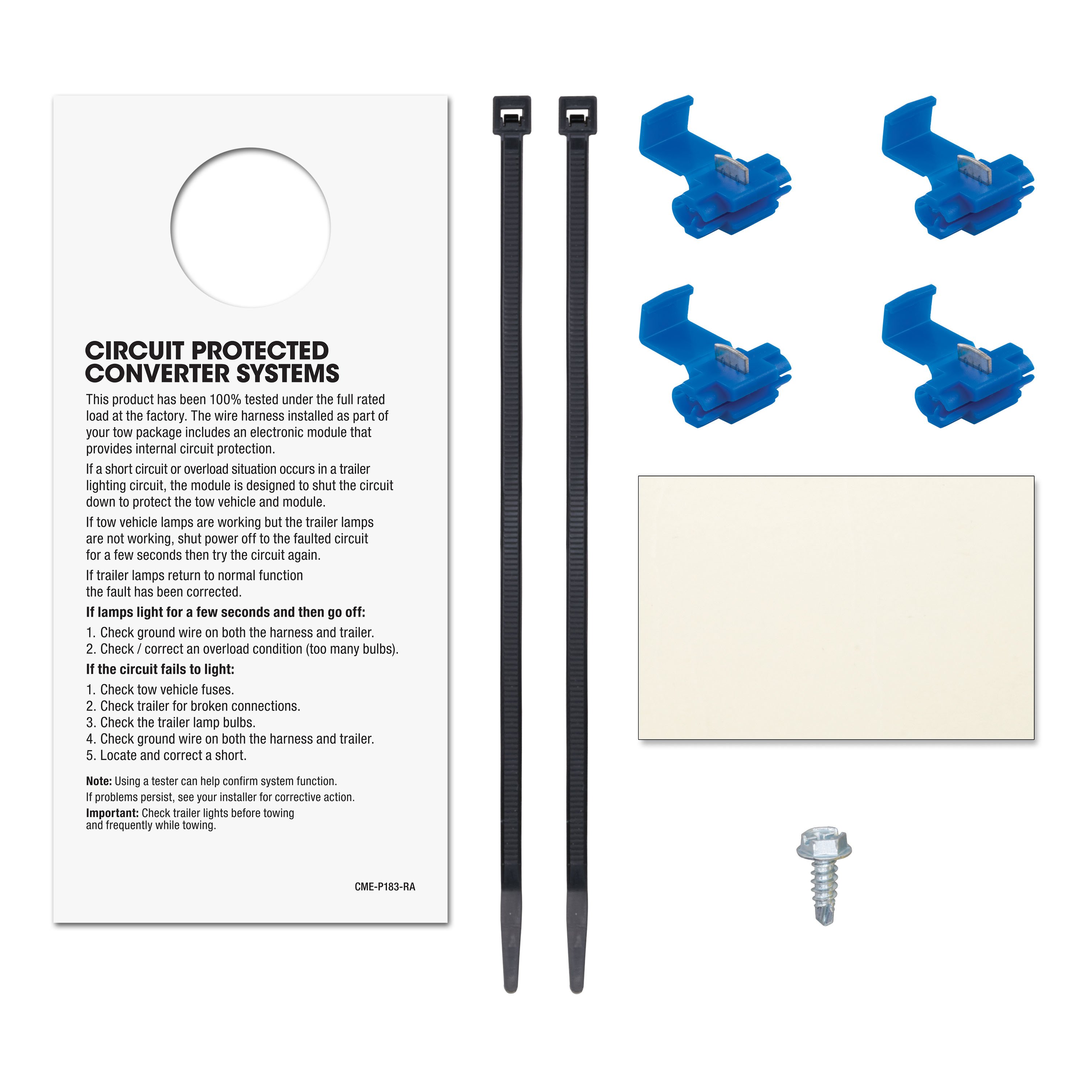
- Snap locks included for fast, secure splicing
- No heavy-duty flasher or direct battery connection required
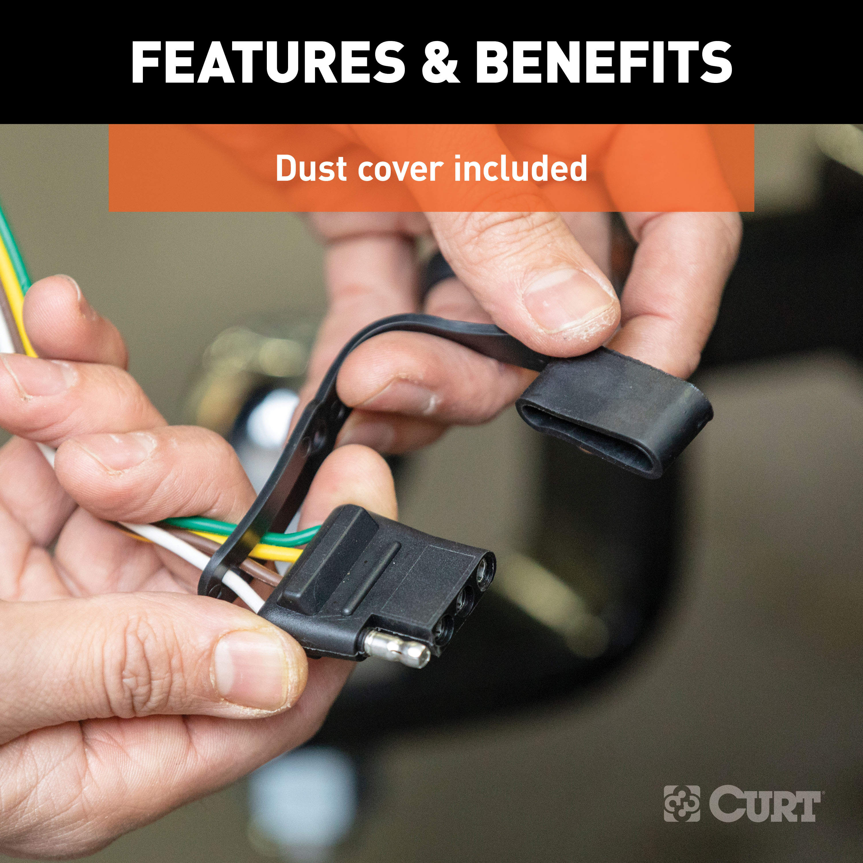
- Dust cover included to keep connector clean when not in use
CURT 57187 4-Way to 5-Way Flat Adapter for Boat Trailer Surge Brakes and CURT 58303 Vehicle-Side Trailer Wiring Harness Mounting Bracket for 5-Way Flat
Manufactured by: Curt
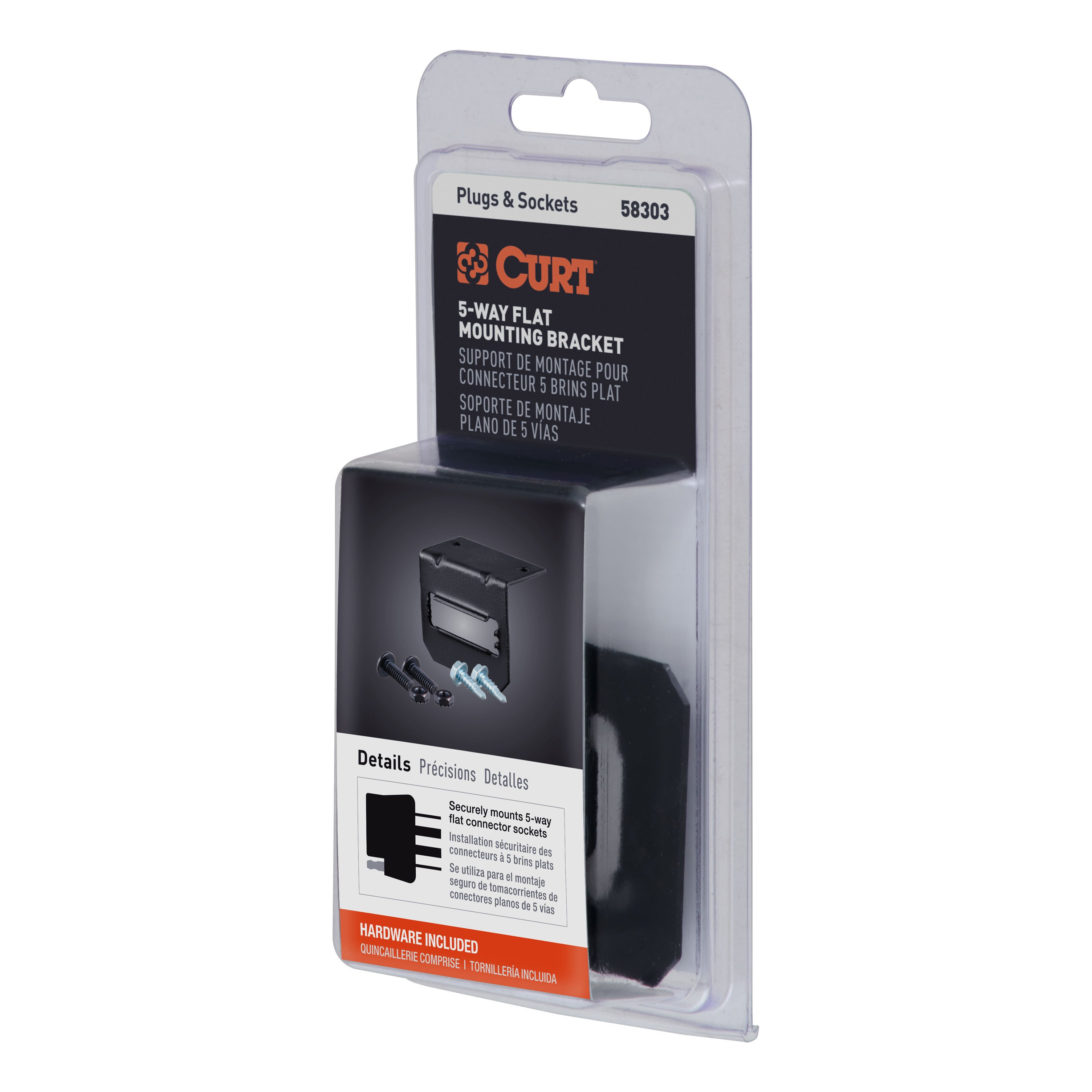
CURT electrical connector brackets provide a simple solution for mounting wiring to your trailer hitch on the rear of your vehicle Connector wires can be a nuisance when they are just lying around; they can get tangled up with cargo and even damaged An electrical connector left to hang off the back end of your vehicle is an even greater hazard.
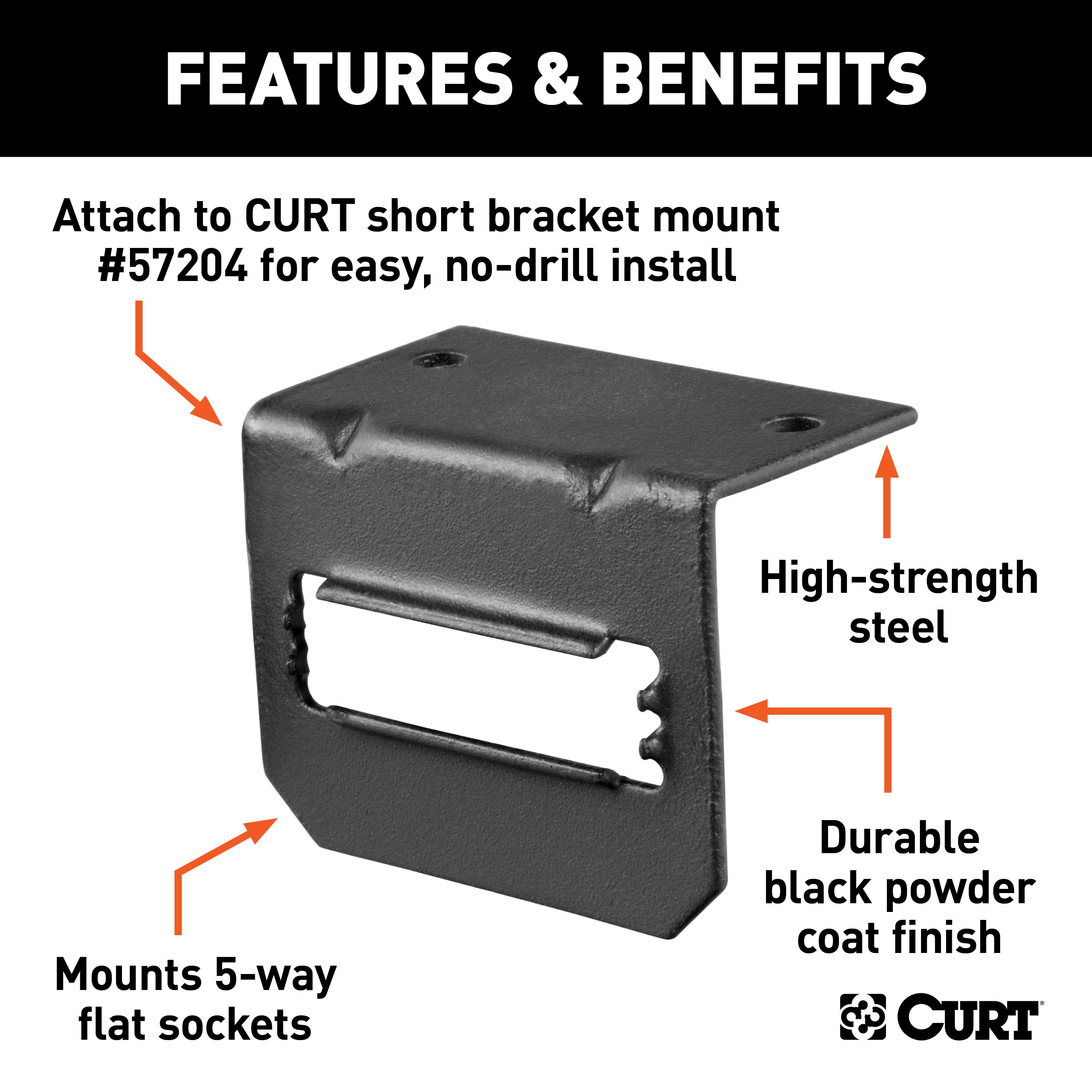
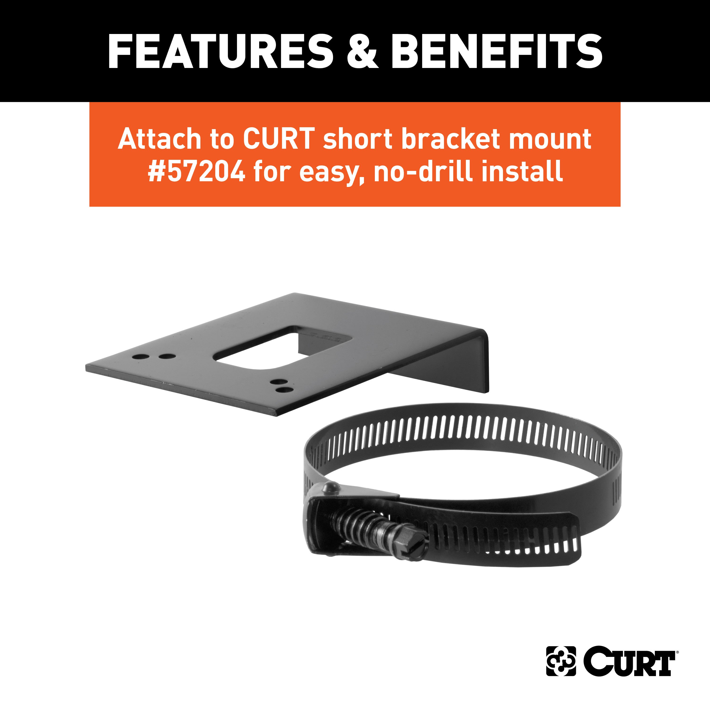
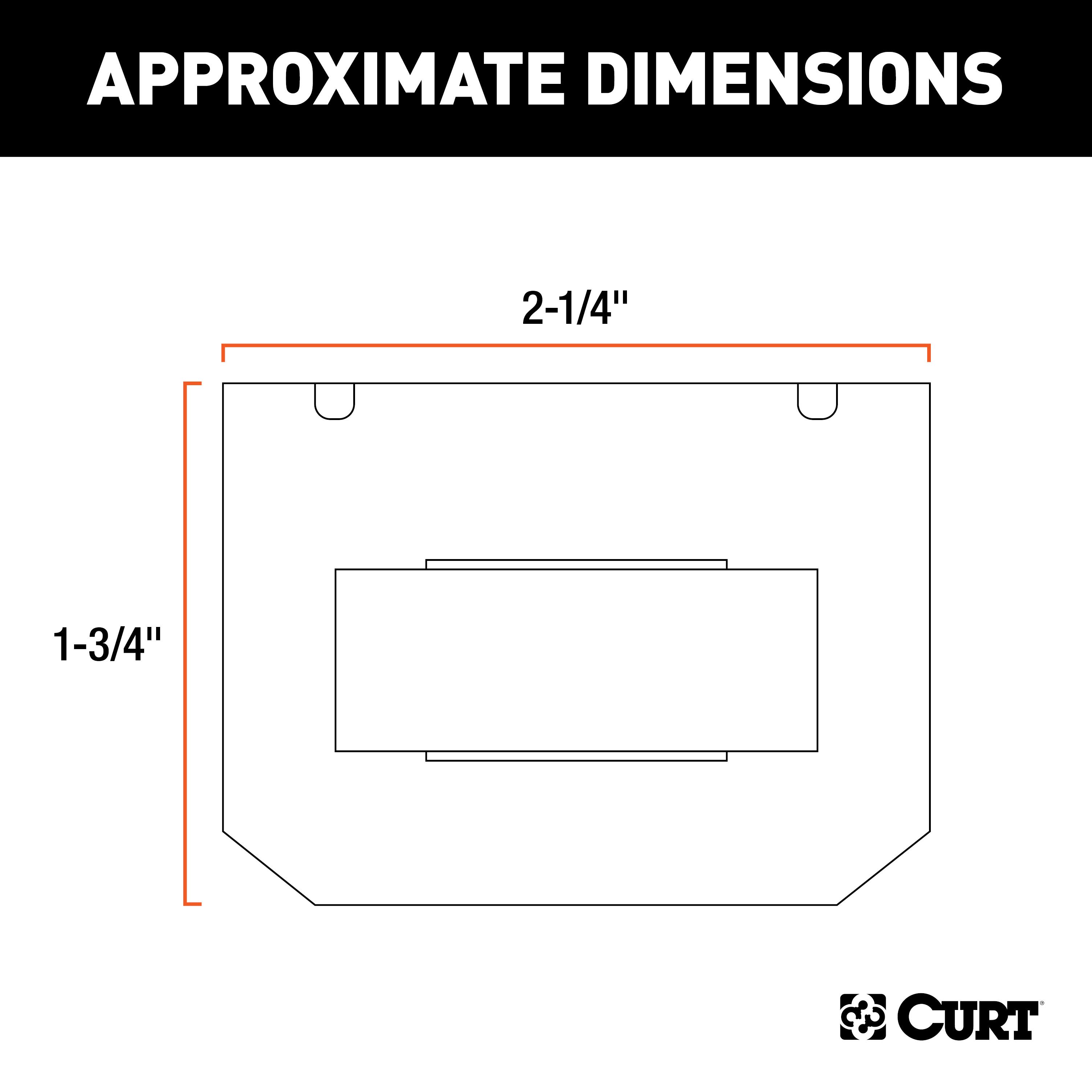
Secure, protect, and optimize the use of your electrical connector by mounting it with a CURT connector bracket This trailer wire connector bracket is designed to hold a 5-way flat socket It features sturdy steel construction with a black finish and can be mounted on your vehicle or trailer hitch using the included hardware.
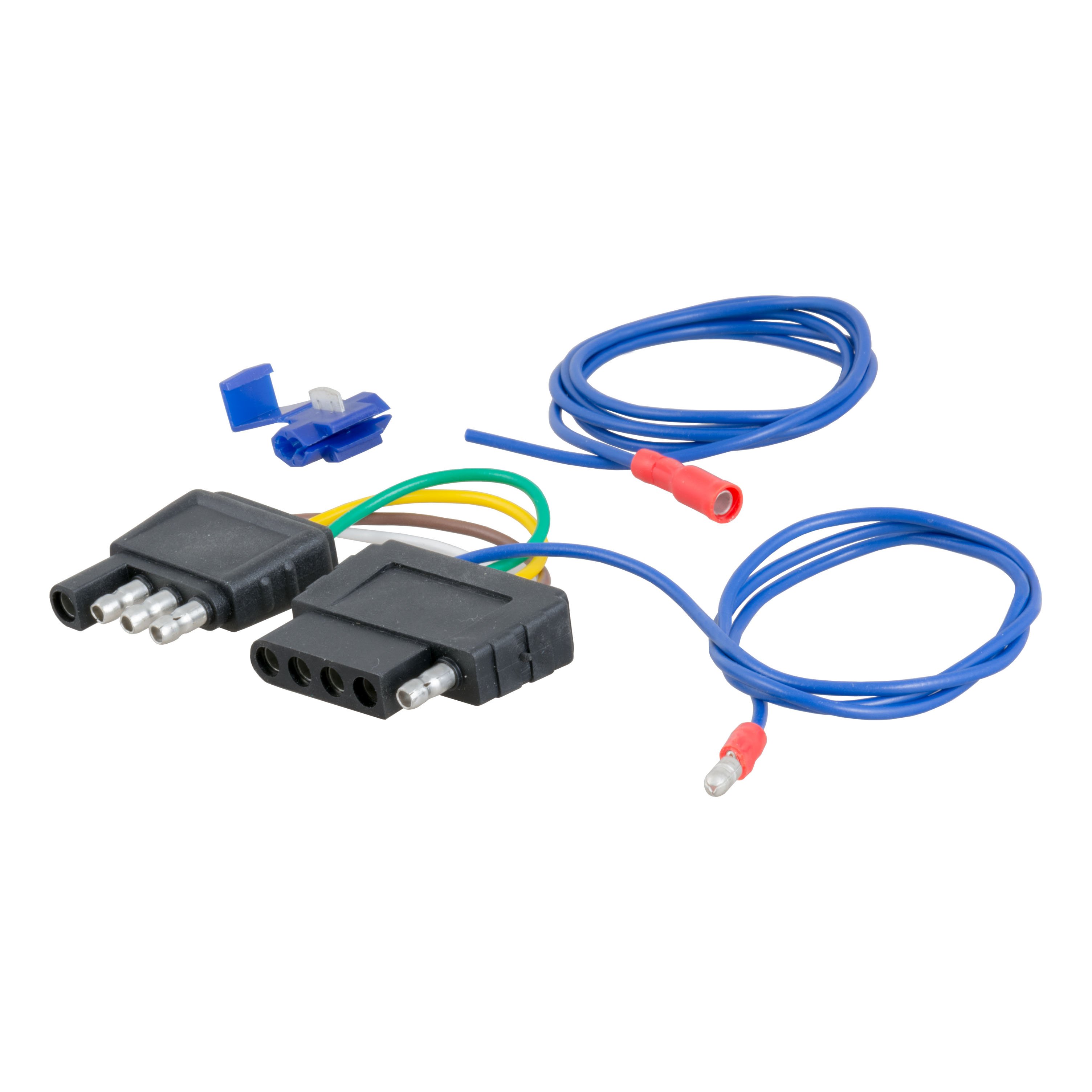
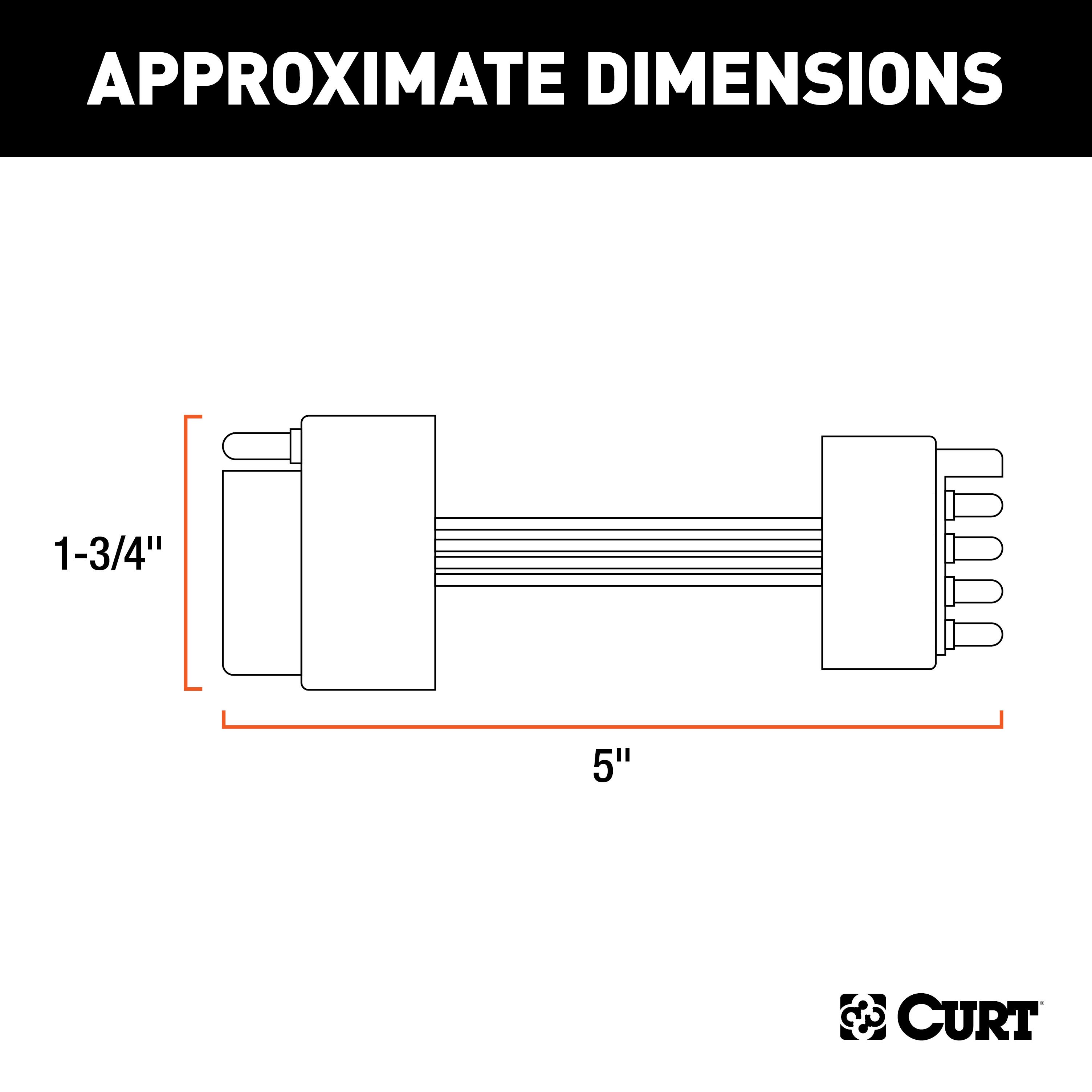
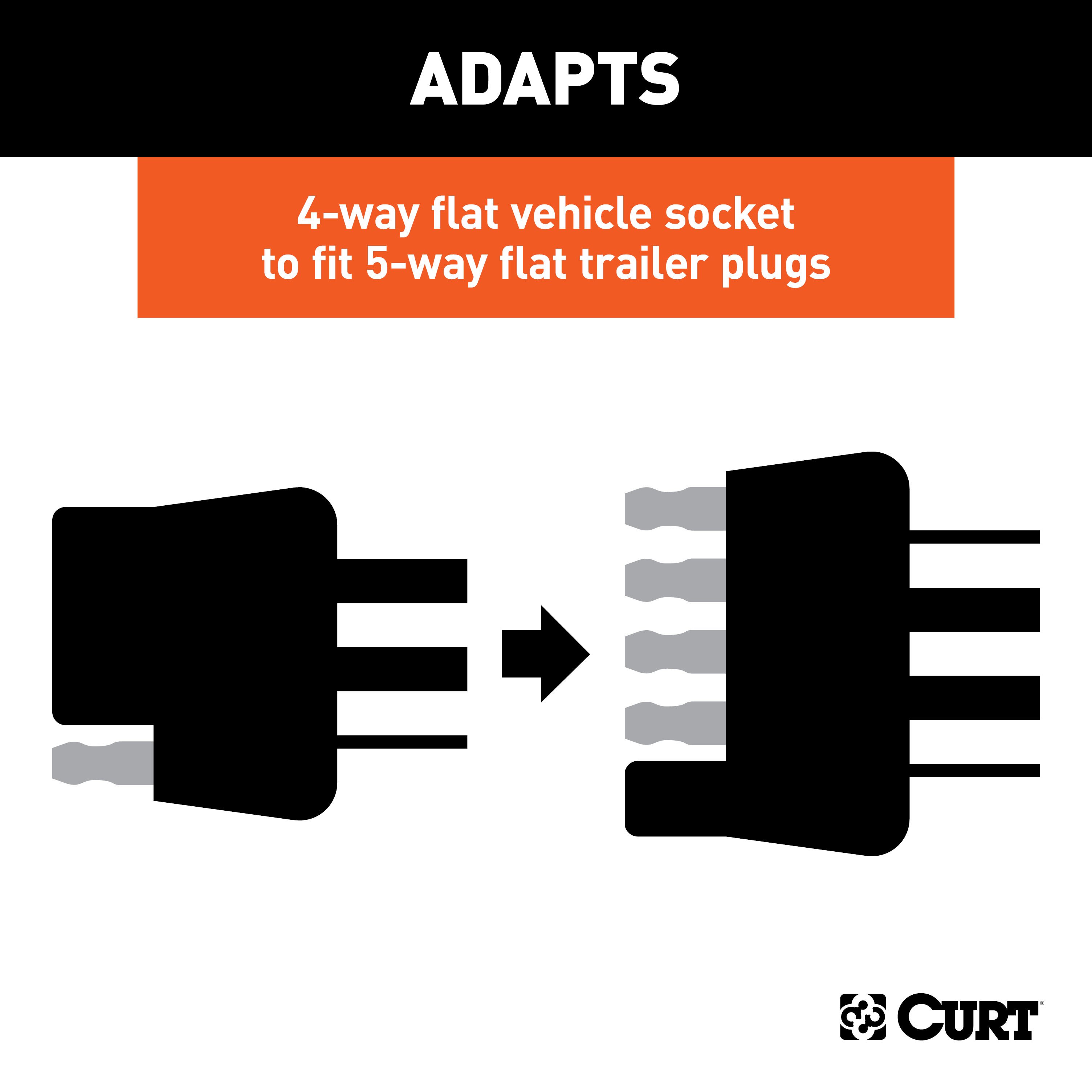
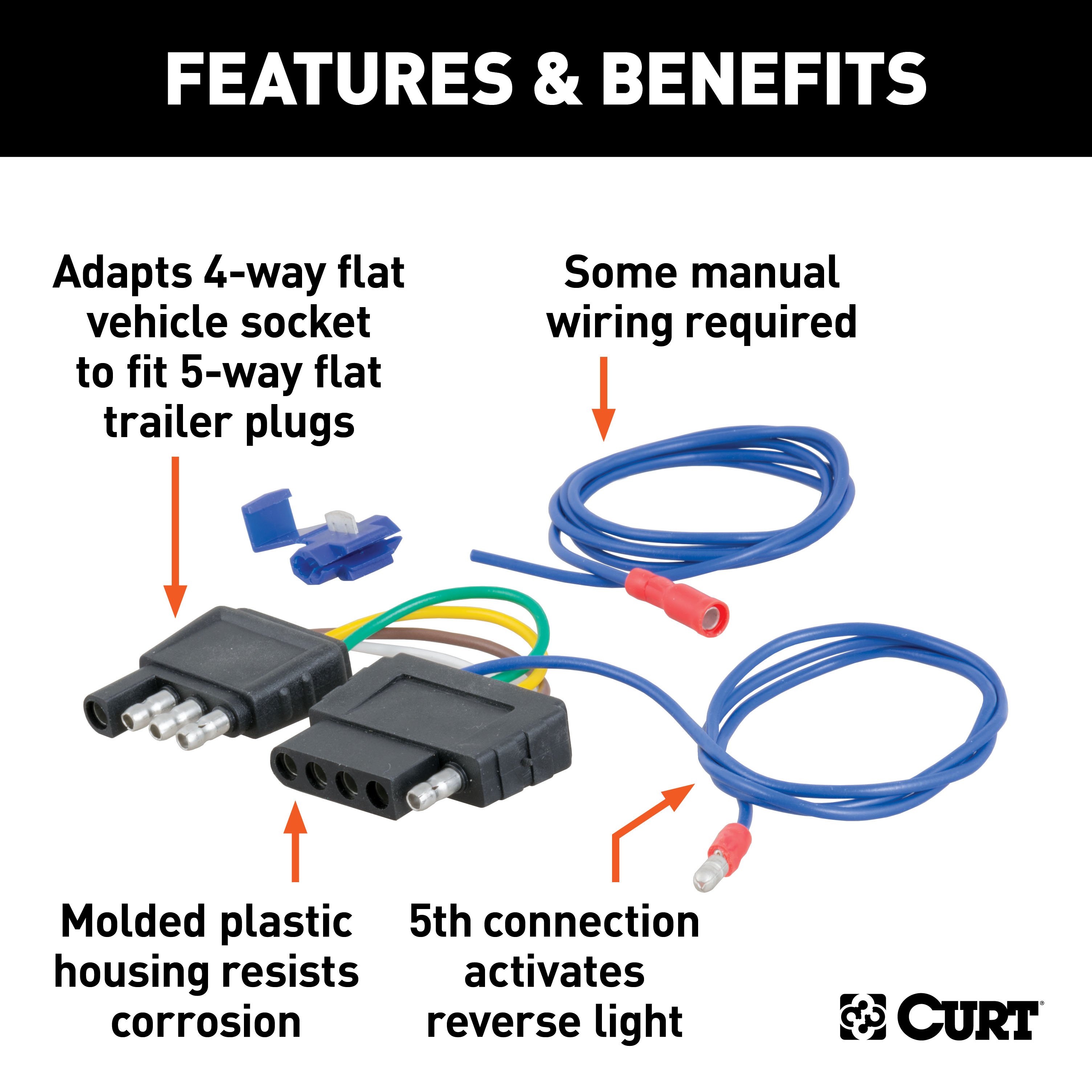
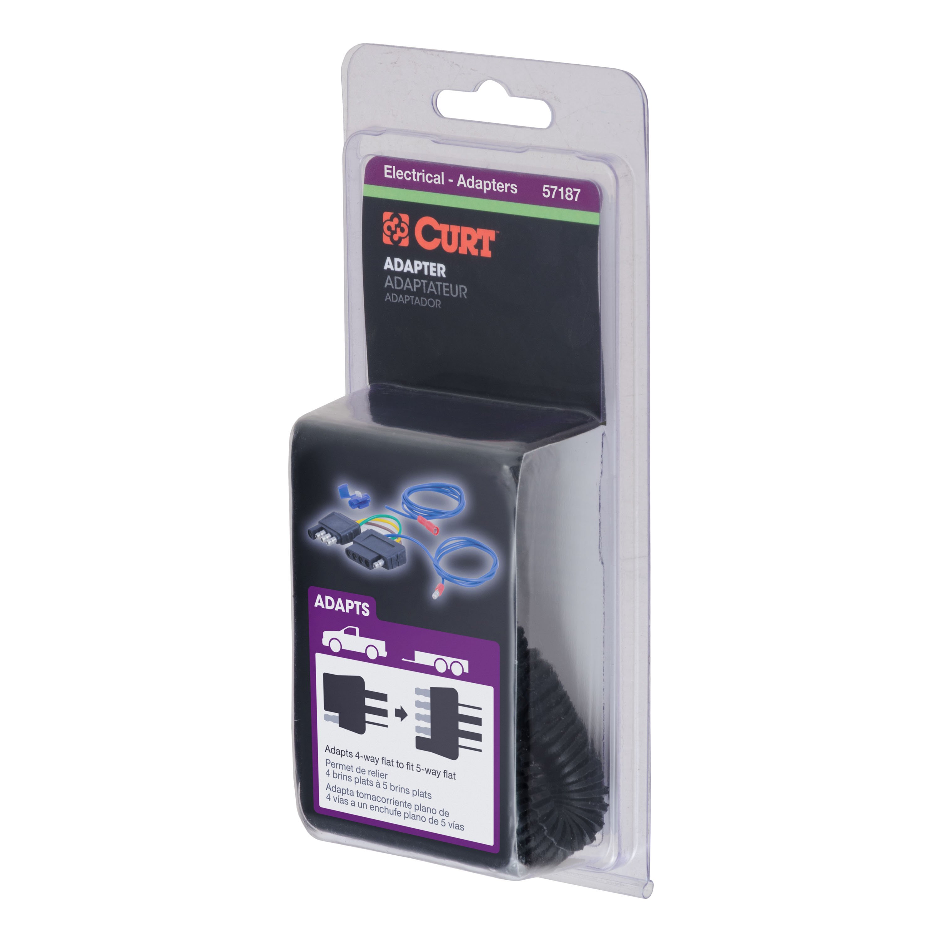
This electrical adapter is designed to adapt a 4-way flat vehicle socket to fit a 5-way flat trailer plug It is specifically intended for boat trailers with surge brakes, adding in a fifth wire for the reverse lights and allowing your vehicle's 4-way flat to easily plug into your boat trailer 5-way flat This boat trailer wiring adapter features durable molded plastic construction and requires some splicing.
All CURT wiring and electrical products come with a one-year limited warranty to give you the assurance you need to tow with confidence..
Features:
- Adapts vehicle 4-way flat to plug into boat trailer 5-way flat
- Intended for boat trailers with surge brakes
- Fifth wire splices in to connect reverse lights
- Adapts 4-way flat vehicle socket to fit 5-way flat trailer plugs
- Durable molded plastic housing resists corrosion
- Securely mounts a 5-way flat connector socket
- Allows for attachment to the vehicle or trailer hitch
- Constructed from high-strength steel
- Protected by a durable black powder coat finish
Hitches Near Me: We operate out of several warehouses across the country, ensuring faster delivery to your location.
$321 99 $439.80 27% OFF
- Best Price on Web Guarantee
- Fastest Shipping
- FREE Shipping
- In Stock

We match lower prices from major authorized retailers for brand-new products in original packaging, provided the item is in stock. The competing seller must be an authorized, professional retail business; offers from
individuals, auctions, peer-to-peer sites, or unauthorized sellers don’t qualify. Used, refurbished, or open-box items are excluded.
Please see our full terms for details.
Verify Fitment
View products that fit your vehicle
Fits 's with the following styles:
View products that fit your vehicle
Fits 's with the following styles:
$439.80 $321 99
 Learn more
Questions? Call our Auto Experts at (877) 869-6690
Get it now, pay later
Select installments at checkout to split your purchase into 4 interest-free payments of $ every 2 weeks.
- No fees, ever.
- No impact on your credit score.
Payment options are offered by Affirm and are subject to an eligibility check and might not be available in all states. CA Residents: Loans by Affirm Loan Services, LLC are made or arranged pursuant to a California Finance Lender license.
Installments in partnership with

Product Details
- Brand: Curt
- Model: 11066 56175 57187 58303-CH3676
- Includes: Class 1 Trailer Tow Hitch, Non-Powered 3-to-2-Wire Taillight Converter, 4-Way to 5-Way Flat Adapter for Boat Trailer Surge Brakes, Connector Mounting Bracket for 5-Way Flat
Compatibility Chart
| Year Range | Make | Model | Style |
|---|
| Default | |
| Part Number | 11066, 56175, 57187-58303 |
| UPC | 612314010301, 612314561759, 612314571871 612314583034 |
| Item Weight | 18.000, 0.590, 0.7 |
| Country of Manufacture | US |
| Main Body Shape | Square |
| Output Type | 5-Way Flat Plug |
| Receiver Tube Size | 1-1/4 IN |
| Finish | GLOSS BLACK POWDER COAT |
| WC / TW (Pounds) | 200 LB / 2,000 LB |
| Weight Carrying Capacity (Pounds) | 2,000 LB |
| WC Tongue Weight (Pounds) | 200 LB |
| Installation Difficulty | Novice |
| Notes | Golf and GTI applications start at 1999.5, Trailer hitch weight ratings are limited to vehicle manufacturer's stated capacities, Includes installation hardware, Includes mounting hardware |
| Warranty | Limited Lifetime Warranty (One-Year Finish, One-Year Parts), One-Year Limited Warranty |
| product_attribute | Some manual wiring required |
| Approx Installation Time (Minutes) | 45 |
Ask a Question about For 1998-2010 VW Beetle Trailer Hitch + Wiring 5 Pin Fits All Including Convertible (Except Turbo) Curt 11066 1-1/4 Tow Receiver
Be the first to ask a question.
Description
This Trailer Tow Hitch + 5-Flat Fits The Following Vehicles:
1998 - 2010 Volkswagen Beetle All Including Convertible (Except Turbo)
This Trailer Tow Hitch + 5-Flat Includes the Following Parts:
- Class 1 Trailer Hitch, 1-1/4" Receiver (Drilling Required)
- 3-to-2-Wire Taillight Converter (Requires Splicing)
- 4-Way to 5-Way Flat Install Kit for Boat Trailer Surge and Connector Mounting Bracket for 5-Way Flat
- Installation instructions, schematics, diagrams, and hardware (if required).
List of Fitment Years:
1998, 1999, 2000, 2001, 2002, 2003, 2004, 2005, 2006, 2007, 2008, 2009, 2010
CURT 11066 Class 1 Trailer Hitch, 1-1/4-Inch Receiver
Manufactured by: Curt
However you define adventure -- whether it's climbing onto the back of a mountain bike, hunting from the top of a tree stand or camping with the family a long way from nowhere -- CURT class 1 hitches provide a light-duty towing receiver to help you Bring It Each is made to fit a specific vehicle, providing easier installation, a better fit and optimal towing capacity Custom class 1 trailer hitches are available for a variety of smaller vehicle types, including the compact car, crossover, minivan and small SUV.
This particular class 1 hitch is designed to be a custom hitch for certain years of the Volkswagen Beetle, Golf and Golf City (to verify vehicle compatibility, see the CURT fitment guide at trailerjacks.com) Tested in accordance with SAE J684, it offers a weight carrying capacity of 2,000 lbs GTW and 200 lbs.
TW It is equipped with 1-1/4" receiver tube opening to accept a ball mount shank or other hitch mount This class 1 hitch also comes with all necessary mounting hardware.
With its lightweight design and smaller receiver tube size, a class 1 hitch is especially useful for adding cargo space with a hitch-mounted bike rack or cargo carrier They can also typically be used to tow small trailers such as a utility trailer, kayak trailer or teardrop camper (never exceed the lowest weight capacity of any towing component; i.e the vehicle, hitch, trailer, etc).
Though CURT class 1 trailer hitches are only intended for light-duty towing, we apply the same principles of quality as we do to the rest of our rear mount hitches Each class 1 hitch is made with hands-on engineering, high-strength steel and precise welding We use a co-cured finish of liquid A-coat, inside and out, and durable black powder coat to provide a lasting defense against rust, chips and UV rays..
Features:
- Rated to 2,000 lbs. gross trailer weight and 200 lbs. tongue weight
- Engineered with a vehicle-specific design for a custom fit
- Tested for safety in accordance with SAE J684
- Precisely welded for superior strength and fit
- Protected by a durable high-gloss black powder coat finish
- Co-cured in a rust-resistant liquid A-coat, inside and out
- Equipped with an open-back receiver for easy cleaning
- Limited lifetime warranty (one-year finish, one-year parts)
- Made in USA (may include imported hardware)
CURT 56175 Non-Powered 3-to-2-Wire Splice-in Tail Light Converter, 4-Pin Wiring Harness
Manufactured by: Curt
When your vehicle does not readily provide an electrical connection for hooking up your trailer, CURT electrical converts offer the solution Working tail lights on your trailer are absolutely essential any time you tow, and a converter provides an effective way to properly equip your vehicle for safe towing A CURT electrical converter, much like our custom vehicle-to-trailer wiring harnesses, provides a trailer connector on your vehicle by splicing into the vehicle's electrical system.
Electrical converters are designed to splice directly into the taillight wiring, rather than plugging into various sockets, giving them the nickname "taillight converters" Though it requires a little extra work compared to a custom wiring harness, a tail light converter offers a reliable, long-term connector solution This CURT electrical converter is designed to convert a 3-wire system to a 2-wire system and provides a standard 4-way flat connector socket to plug in your trailer.
It is designed to fit certain models of Acura, Audi, Buick, Chevrolet, Chrysler, Dodge, Eagle, Ford, Geo, Honda, Hyundai, Infiniti, Isuzu, Kia, Mazda, Mercedes, Mercury, Mitsubishi, Nissan, Oldsmobile, Peugeot, Plymouth, Pontiac, Saturn, Suzuki, Toyota, Volkswagen and Volvo (to verify your vehicle compatibility, see the CURT fitment guide at trailerjacks.com) This converter is made with cutting-edge surface-mount technology (SMT) circuitry, featuring electrical components that are mounted directly to the surface of the board rather than being inserted into a series of holes SMT circuits have longer life cycles, lower resistance, reduced heat generation and are more reliable than through-hole-mounted components..
Features:
- Converts 3-wire vehicle electrical system to standard 2-wire trailer wiring
- 4-way flat output connects tail lights, brake lights and turn signals
- Constructed with SMT circuitry for better performance and durability
- Color-coded wires for easier installation
- Snap locks included for fast, secure splicing
- No heavy-duty flasher or direct battery connection required
- Dust cover included to keep connector clean when not in use
CURT 57187 4-Way to 5-Way Flat Adapter for Boat Trailer Surge Brakes and CURT 58303 Vehicle-Side Trailer Wiring Harness Mounting Bracket for 5-Way Flat
Manufactured by: Curt
CURT electrical connector brackets provide a simple solution for mounting wiring to your trailer hitch on the rear of your vehicle Connector wires can be a nuisance when they are just lying around; they can get tangled up with cargo and even damaged An electrical connector left to hang off the back end of your vehicle is an even greater hazard.
Secure, protect, and optimize the use of your electrical connector by mounting it with a CURT connector bracket This trailer wire connector bracket is designed to hold a 5-way flat socket It features sturdy steel construction with a black finish and can be mounted on your vehicle or trailer hitch using the included hardware.
This electrical adapter is designed to adapt a 4-way flat vehicle socket to fit a 5-way flat trailer plug It is specifically intended for boat trailers with surge brakes, adding in a fifth wire for the reverse lights and allowing your vehicle's 4-way flat to easily plug into your boat trailer 5-way flat This boat trailer wiring adapter features durable molded plastic construction and requires some splicing.
All CURT wiring and electrical products come with a one-year limited warranty to give you the assurance you need to tow with confidence..
Features:
- Adapts vehicle 4-way flat to plug into boat trailer 5-way flat
- Intended for boat trailers with surge brakes
- Fifth wire splices in to connect reverse lights
- Adapts 4-way flat vehicle socket to fit 5-way flat trailer plugs
- Durable molded plastic housing resists corrosion
- Securely mounts a 5-way flat connector socket
- Allows for attachment to the vehicle or trailer hitch
- Constructed from high-strength steel
- Protected by a durable black powder coat finish
Hitches Near Me: We operate out of several warehouses across the country, ensuring faster delivery to your location.


