Product Details
- Brand: Curt
- Model: 12094 55537-CH733
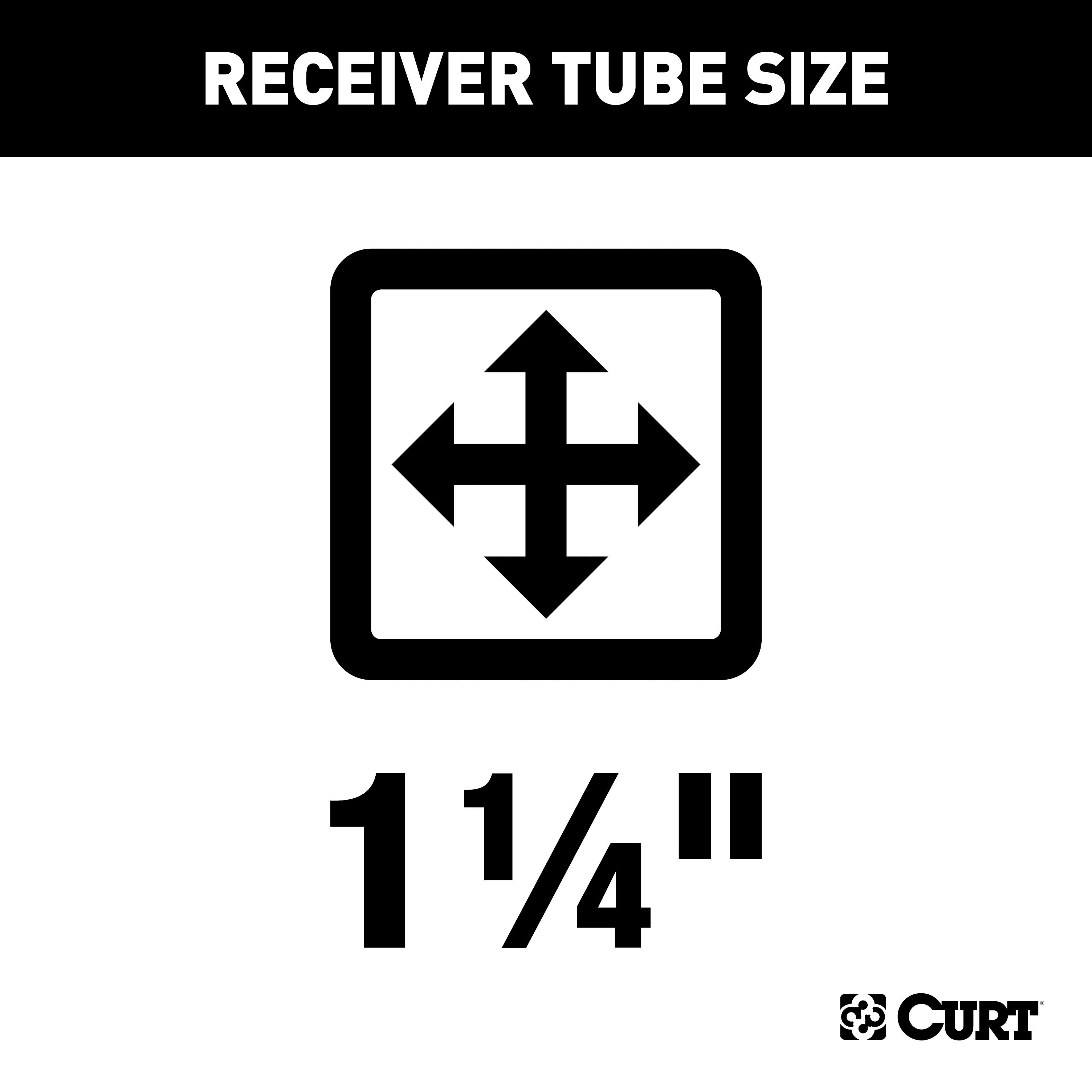
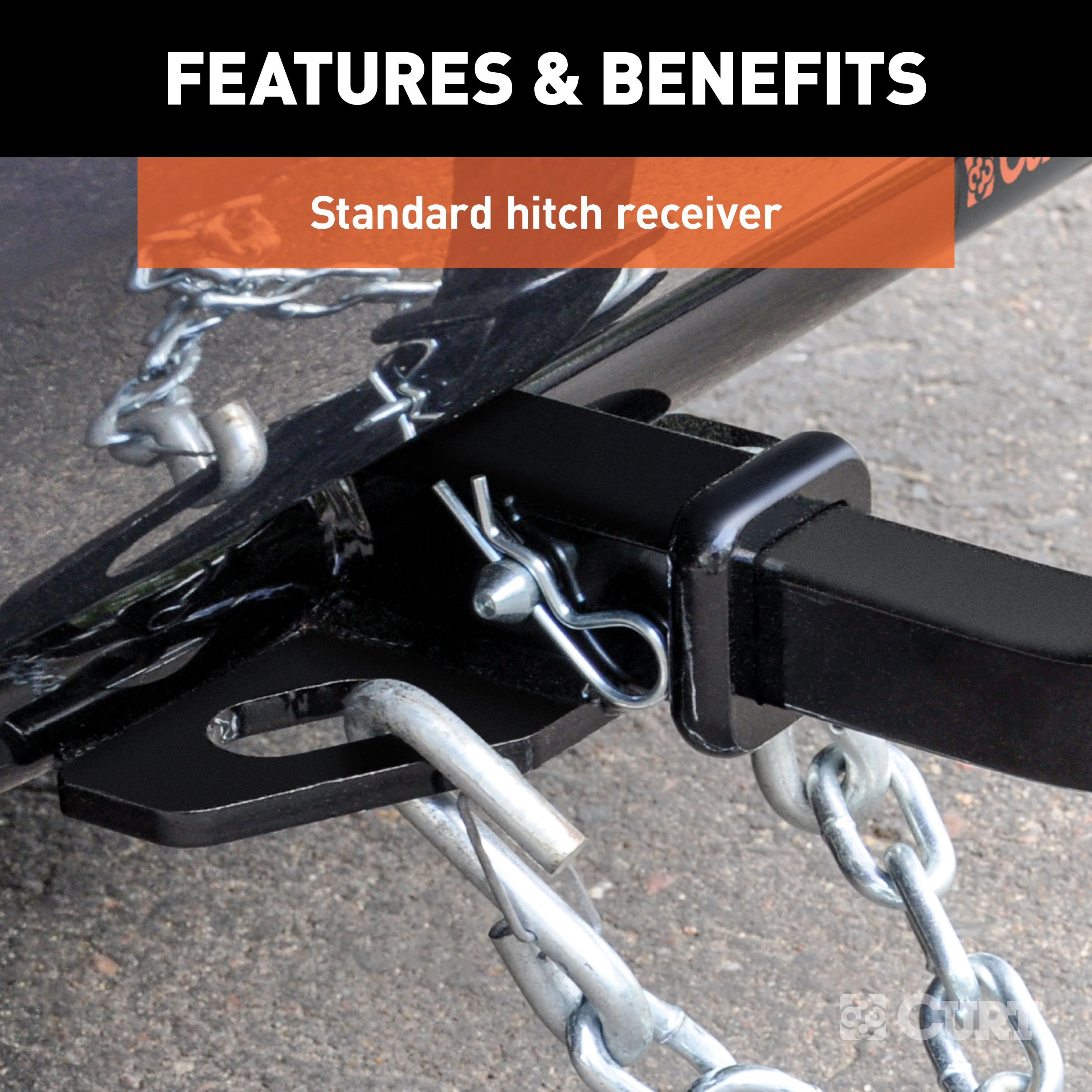
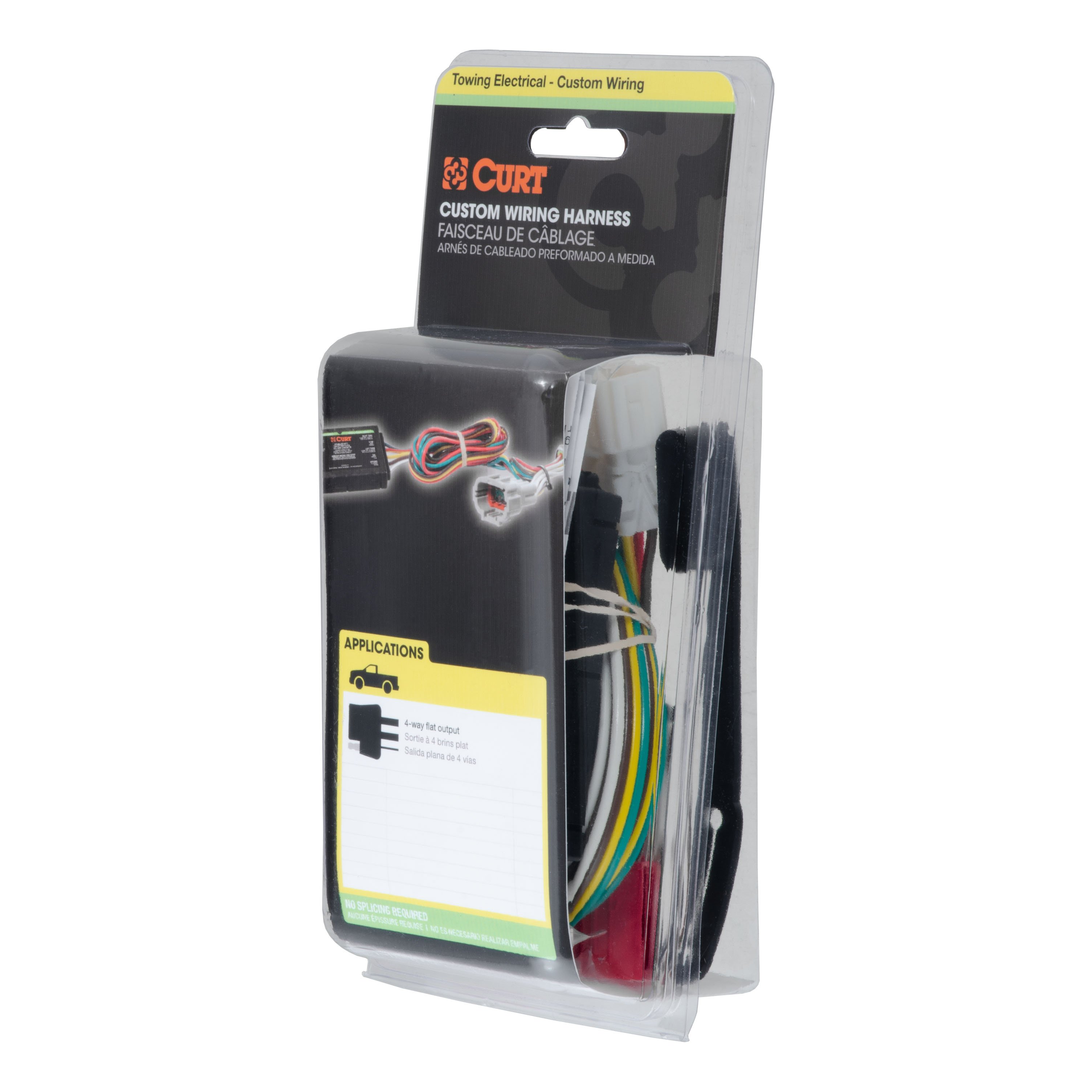
- Includes: Class 2 Trailer Tow Hitch, Custom Wiring
Compatibility Chart
Description
Get Expert Help
For 2004-2007 Chrysler Town & Country Trailer Hitch + Wiring 4 Pin Except Stow 'n Go Curt 12094 55537 1-1/4 Tow Receiver Install Notes
Installation Instructions for 1996-2007 Chrysler Town & Country, Dodge Caravan, and Plymouth Voyager (Including Sport Models)
Part Numbers:
- 12094
Wiring Access Location:
Not specified.
Tools Required:
- Torque wrench
- Ratchet
- Socket: 19mm
Step-by-Step Instructions:
-
Raise the Vehicle:
- Safely raise the vehicle to gain access to the underside.
-
Remove Existing Fasteners:
- Remove the two rearmost bolts from the vehicle frame (two bolts per side).
-
Position the Hitch:
- Raise the hitch into position so that the mounting holes align with the existing weld nuts in the vehicle frame.
-
Install Bolts:
- Reinstall the bolts removed in Step 2 to secure the hitch.
-
Torque Fasteners:
- Torque all fasteners to 79 lb-ft using a torque wrench.
-
Final Inspection:
- Periodically check this receiver hitch to ensure all fasteners remain tight and structural components are sound.
Hardware List:
- Hex Bolt, M12 x 1.75 x 35, Class 10.9, YZ: Qty 4 (Part No. 10-10516)
- Washer, S-Con, 1/2, YZ: Qty 4 (Part No. 30-00149)
Safety Notes:
- Gross Load Capacity (Weight Carrying Hitch): 3,500 lbs (trailer weight), 350 lbs (tongue weight).
- Do not exceed the vehicle manufacturer's recommended towing capacity.
- Warning: All non-trailer loads must be supported by auxiliary stabilizing straps.
Failure to properly support non-trailer loads will void the product warranty.
Specifications:
- Hitch Weight: Not specified.
- Installation Time:
- Professional: 25 minutes
- Novice (DIY): 31 minutes
- Drilling Required: No
Manufacturer Notes:
- Designed for use with Ball Mount #D-21 / 45521.
- Periodically check this receiver hitch to ensure all fasteners remain tight and structural components are sound.
- Warranty covers defects in material and workmanship at the time of purchase.
- For technical support, call Curt Manufacturing at 1-877-287-8634.
Installation Instructions for 1996-2007 Chrysler Town & Country, Dodge Caravan, and Plymouth Voyager (Including Sport Models)
Part Numbers:
- 12094
Wiring Access Location:
Not specified.
Tools Required:
- Torque wrench
- Ratchet
- Socket: 19mm
Step-by-Step Instructions:
-
Raise the Vehicle:
- Safely raise the vehicle to gain access to the underside.
-
Remove Existing Fasteners:
- Remove the two rearmost bolts from the vehicle frame (two bolts per side).
-
Position the Hitch:
- Raise the hitch into position so that the mounting holes align with the existing weld nuts in the vehicle frame.
-
Install Bolts:
- Reinstall the bolts removed in Step 2 to secure the hitch.
-
Torque Fasteners:
- Torque all fasteners to 79 lb-ft using a torque wrench.
-
Final Inspection:
- Periodically check this receiver hitch to ensure all fasteners remain tight and structural components are sound.
Hardware List:
- Hex Bolt, M12 x 1.75 x 35, Class 10.9, YZ: Qty 4
- Washer, S-Con, 1/2, YZ: Qty 4
Safety Notes:
- Gross Load Capacity (Weight Carrying Hitch):
- 3,500 lbs (trailer weight)
- 350 lbs (tongue weight)
- Do not exceed the vehicle manufacturer's recommended towing capacity.
- Warning: All non-trailer loads must be supported by auxiliary stabilizing straps.
Failure to properly support non-trailer loads will void the product warranty.
Specifications:
- Hitch Weight: Not specified.
- Installation Time:
- Professional: 25 minutes
- Novice (DIY): 31 minutes
- Drilling Required: No
Technical Support:
- For technical support and assistance, our team of experts is available to help.
Visit www.trailerjacks.com or call 877-869-6690.
Warranty Information:
- Warranty covers defects in material and workmanship.
- For complete warranty instructions, please download the full installation PDF.
End of Instructions
Installation Instructions for Chrysler Town & Country, Dodge Caravan, and Dodge Grand Caravan
Part Number:
- 55537
Tools Required:
- Panel trim removal tool
Wiring Access Locations:
- S1: Behind driver side taillight housing
- S2: Behind passenger side taillight housing
Step-by-Step Instructions:
-
Remove Taillight Assemblies:
- Open the rear hatch.
- Remove the two plastic fasteners securing each taillight assembly.
- Carefully remove the taillight assemblies to access the vehicle's taillight wiring harness.
-
Disconnect Taillight Wiring:
- Locate the vehicle's taillight wiring harness connectors behind each taillight.
- Separate the connectors from the taillight housing, ensuring the locking tabs are not damaged.
-
Prepare Grommet for Wiring:
- Locate the grommet behind each taillight where the vehicle's taillight wiring passes from inside the cabin to the taillight.
- Remove the grommet and cut a slit large enough to route the custom wiring harness through.
-
Access Interior Panels:
- Inside the vehicle, remove the rear scuff panel.
- Partially remove both the driver and passenger side interior trim panels.
- Locate the opening between the back of the taillight and the interior of the vehicle.
-
Route and Connect Driver Side Wiring:
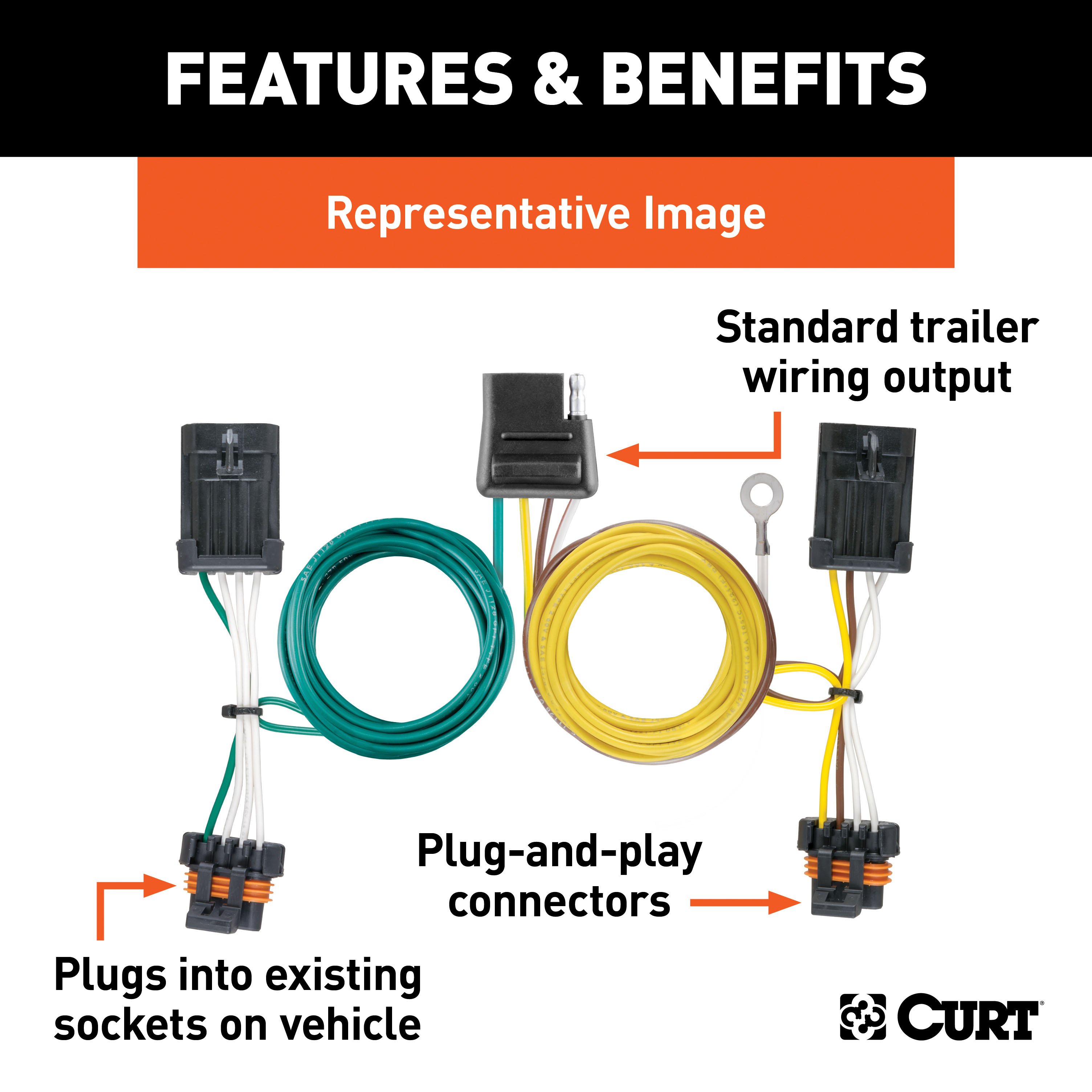
- On the driver side, route the custom wiring harness end with the yellow wire out through the grommet opening and through the slit in the grommet.
- Insert the harness between the separated connectors, ensuring they are fully inserted with locking tabs in place.
-
Seal Grommet:
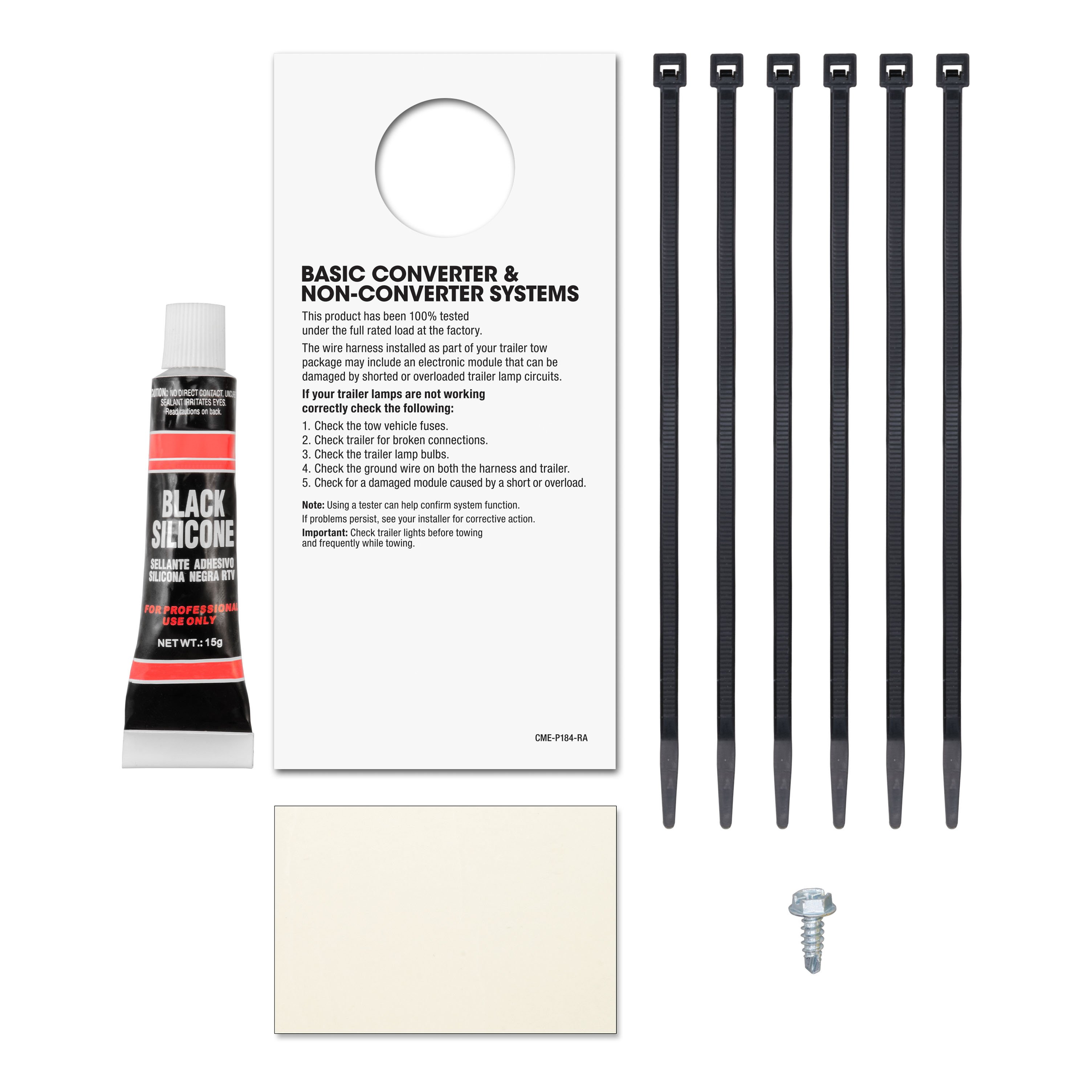
- Reseat the grommet and use the provided sealant to seal the cut and around all the wires.
-
Route and Connect Passenger Side Wiring:
- Route the custom wiring harness end with the green wire to the passenger side behind the removed scuff panels.
- Repeat steps 5 and 6 on the passenger side using the harness end with the green wire.
-
Establish Ground Connection:
- Locate a suitable grounding point near the connector, such as an existing screw with a nut in the vehicle frame, or drill a 3/32" pilot hole for the provided screw.
- Ensure the area is free of rust, dirt, and paint.
- Secure the white ground wire using the ring terminal and provided screw.
Warning: Check for hidden items behind or under any surface before drilling to avoid damage and/or personal injury.
-
Position 4-Flat Connector:
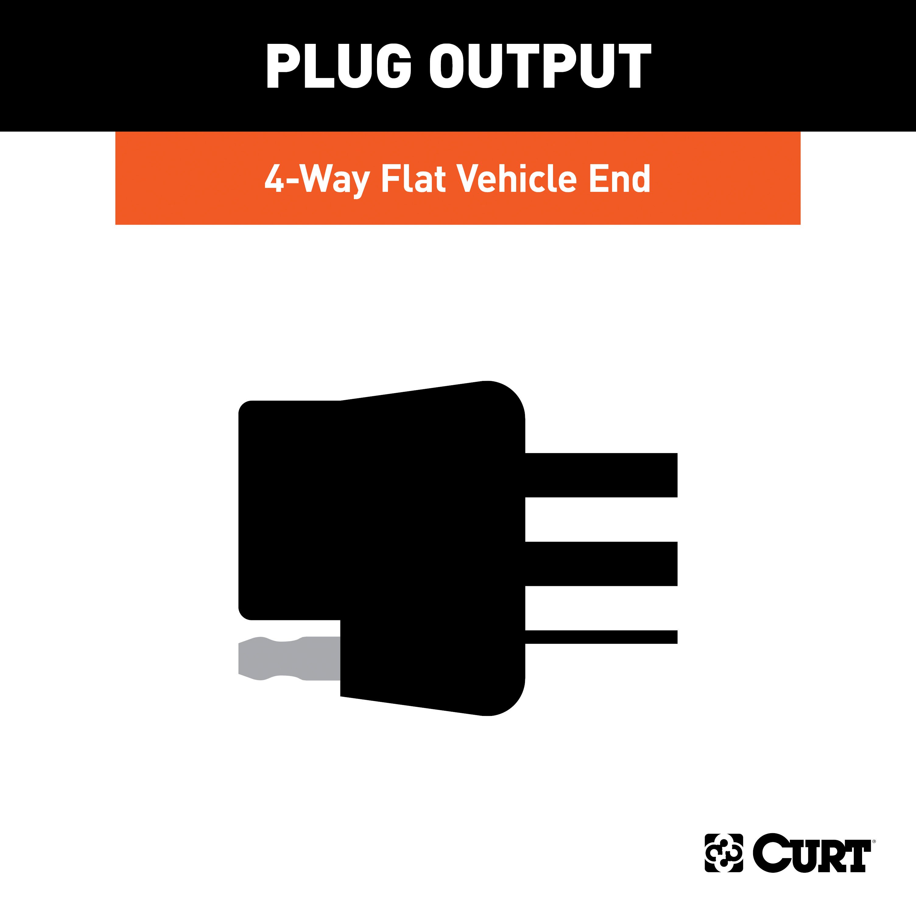
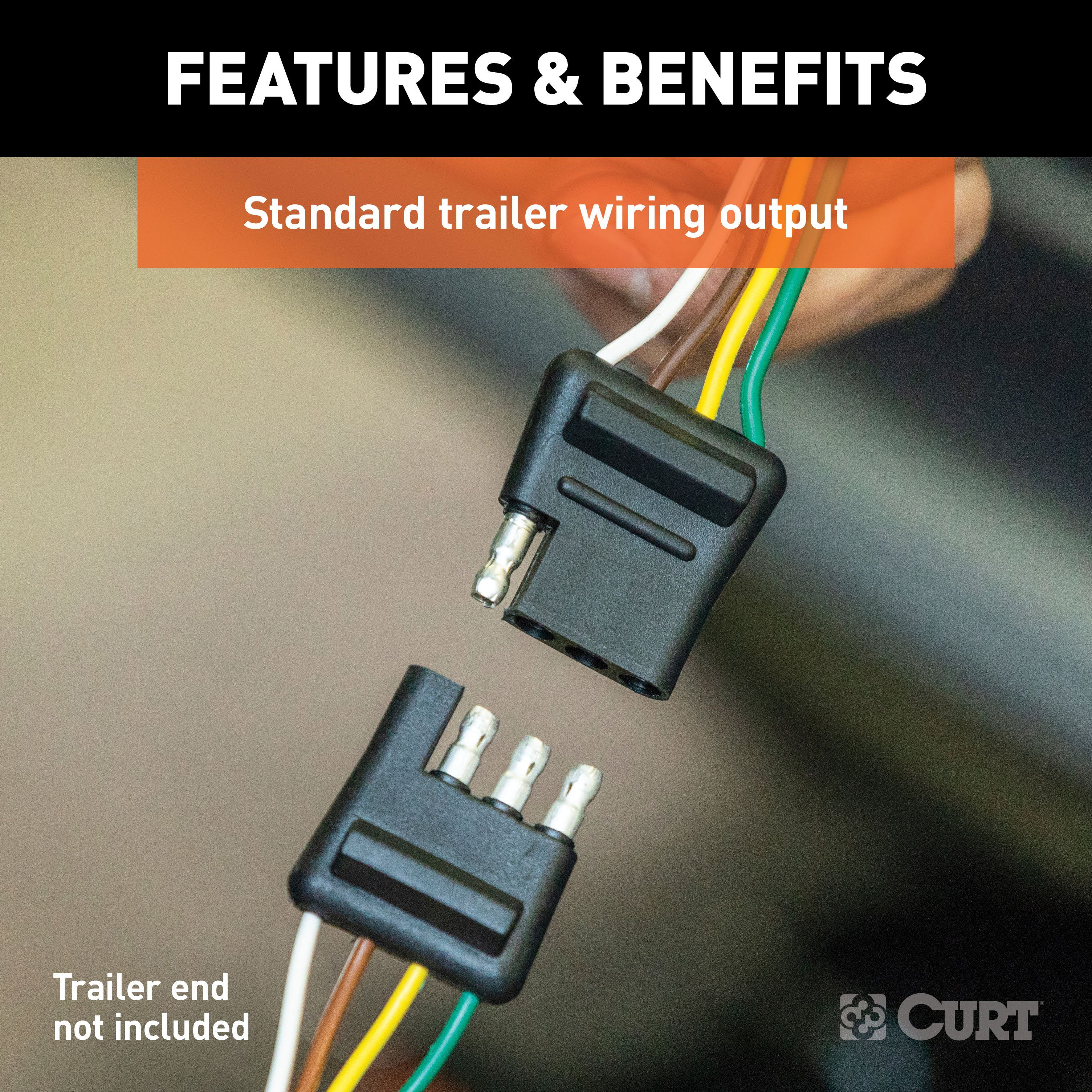
- When in use, route the 4-flat connector to the center of the vehicle and out of the trunk.
- When not in use, roll up and store it in a convenient, out-of-the-way location inside the trunk.
- Secure any loose wires with the provided cable ties.
-
Reassemble Vehicle Components:
- Reinstall all items removed during installation.
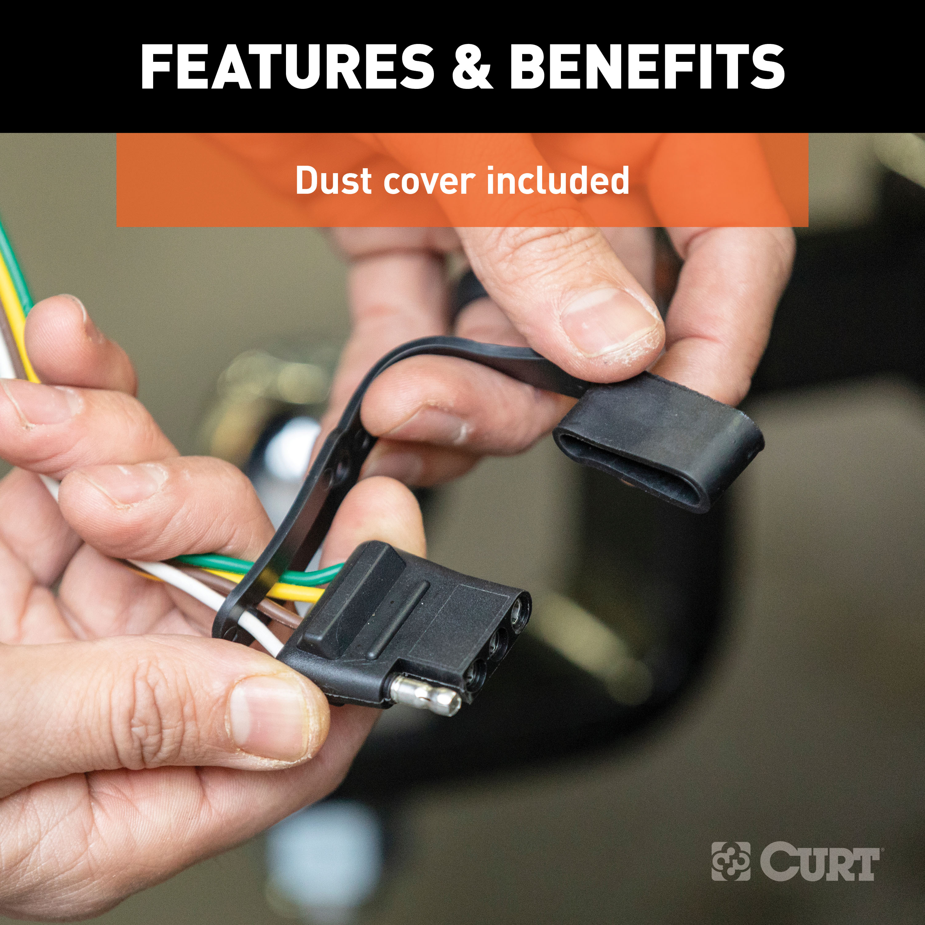
- Install the provided 4-flat dust cover to help prevent corrosion.
Safety Notes:
- Ensure all connectors are fully inserted with locking tabs in place to prevent disconnection.
- Secure loose wires to avoid contact with moving parts or hot surfaces.
- Avoid routing wires through areas that may cut or pinch them.
Warning: Do not exceed the product rating or the tow vehicle's lamp load rating, whichever is lower. Exceeding these ratings can cause loss of warranty, overheating, and potential fire.
Note: For more information, refer to the vehicle owner's manual or contact the vehicle manufacturer.
Installation Instructions for Chrysler Town & Country, Dodge Caravan, and Dodge Grand Caravan
Part Number:
- 55537
Tools Required:
- Panel trim removal tool
Wiring Access Locations:
- S1: Behind driver side taillight housing
- S2: Behind passenger side taillight housing
Step-by-Step Instructions:
-
Remove Taillight Assemblies:
- Open the rear hatch.
- Remove the two plastic fasteners securing each taillight assembly.
- Carefully remove the taillight assemblies to access the vehicle's taillight wiring harness.
-
Disconnect Taillight Wiring:
- Locate the vehicle's taillight wiring harness connectors behind each taillight.
- Separate the connectors from the taillight housing, ensuring the locking tabs are not damaged.
-
Prepare Grommet for Wiring:
- Locate the grommet behind each taillight where the vehicle's taillight wiring passes from inside the cabin to the taillight.
- Remove the grommet and cut a slit large enough to route the custom wiring harness through.
-
Access Interior Panels:
- Inside the vehicle, remove the rear scuff panel.
- Partially remove both the driver and passenger side interior trim panels.
- Locate the opening between the back of the taillight and the interior of the vehicle.
-
Route and Connect Driver Side Wiring:
- On the driver side, route the custom wiring harness end with the yellow wire out through the grommet opening and through the slit in the grommet.
- Insert the harness between the separated connectors, ensuring they are fully inserted with locking tabs in place.
-
Seal Grommet:
- Reseat the grommet and use the provided sealant to seal the cut and around all the wires.
-
Route and Connect Passenger Side Wiring:
- Route the custom wiring harness end with the green wire to the passenger side behind the removed scuff panels.
- Repeat steps 5 and 6 on the passenger side using the harness end with the green wire.
-
Establish Ground Connection:
- Locate a suitable grounding point near the connector, such as an existing screw with a nut in the vehicle frame, or drill a 3/32" pilot hole for the provided screw.
- Ensure the area is free of rust, dirt, and paint.
- Secure the white ground wire using the ring terminal and provided screw.
Warning: Check for hidden items behind or under any surface before drilling to avoid damage and/or personal injury.
-
Position 4-Flat Connector:
- When in use, route the 4-flat connector to the center of the vehicle and out of the trunk.
- When not in use, roll up and store it in a convenient, out-of-the-way location inside the trunk.
- Secure any loose wires with the provided cable ties.
-
Reassemble Vehicle Components:
- Reinstall all items removed during installation.
- Install the provided 4-flat dust cover to help prevent corrosion.
Safety Notes:
- Ensure all connectors are fully inserted with locking tabs in place to prevent disconnection.
- Secure loose wires to avoid contact with moving parts or hot surfaces.
- Avoid routing wires through areas that may cut or pinch them.
Additional Information:
- Attention: This is a summary of the installation procedure. For complete installation instructions, including diagrams and detailed information from the manufacturer, please download the full installation PDF.
Technical Support:
- For technical support and assistance, our team of experts is available to help. You can reach our tech support by visiting www.trailerjacks.com or calling 877-869-6690.
Warranty:
- Warranty Duration: [Insert warranty period]
- Coverage Details: [Insert coverage details]
- For complete warranty information, please download the full installation PDF.
Warning: Do not exceed the product rating or the tow vehicle's lamp load rating, whichever is lower. Exceeding these ratings can cause loss of warranty, overheating, and potential fire.
Note: For more information, refer to the vehicle owner's manual or contact the vehicle manufacturer.


