Product Details
- Brand: Curt
- Model: 12284 59236-CH3482
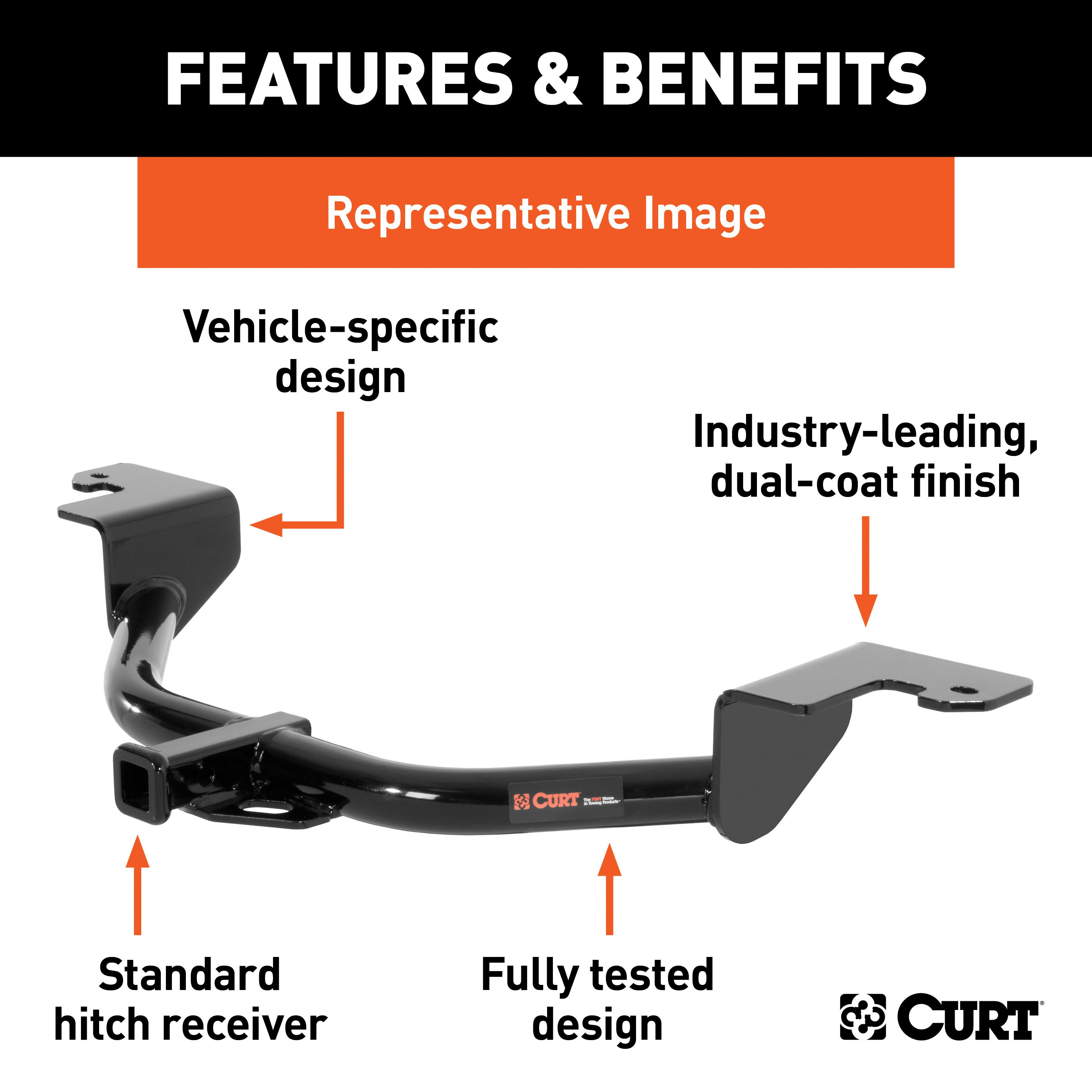
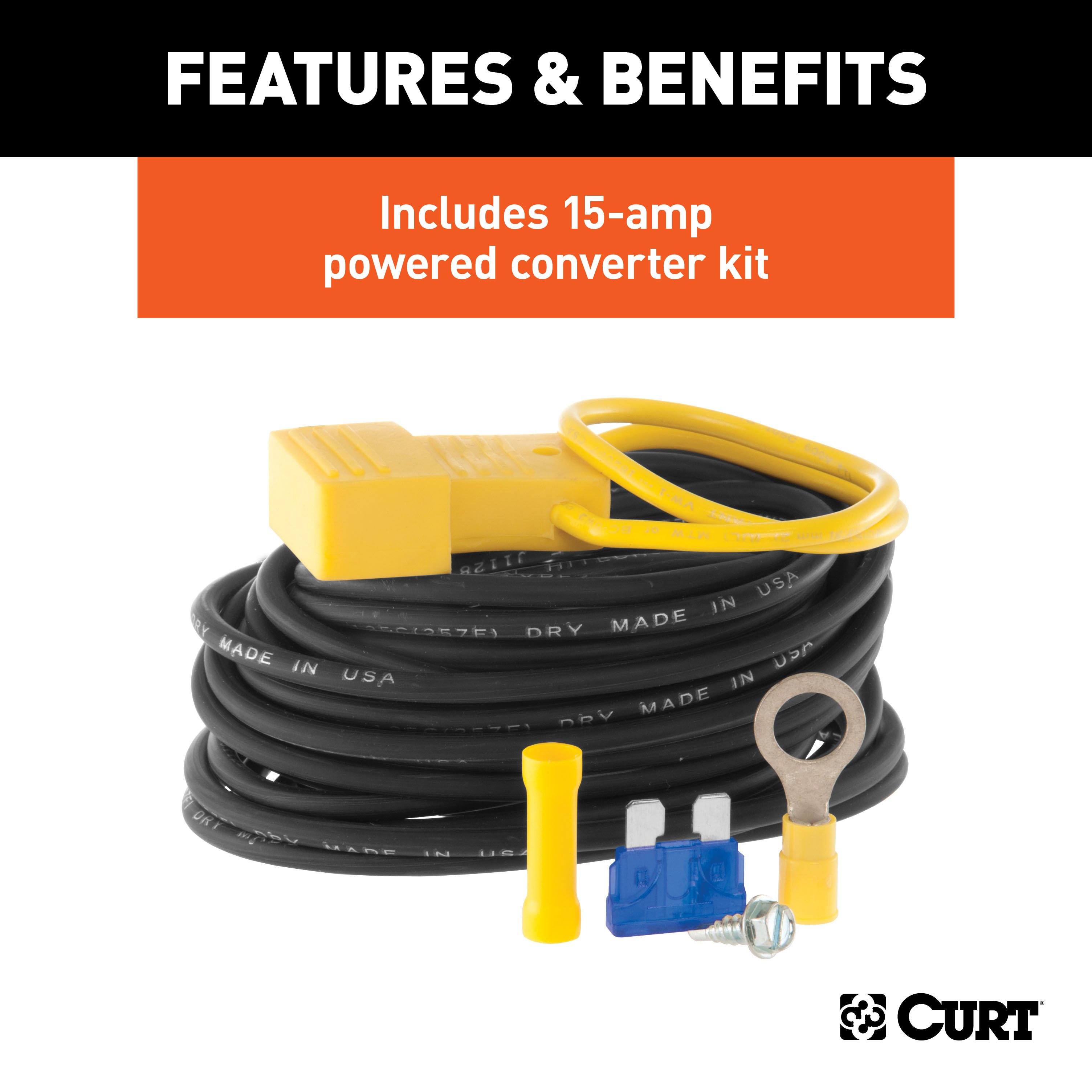
- Includes: Class 2 Trailer Tow Hitch, Multi-Function Taillight Converter Kit
Compatibility Chart
Description
Get Expert Help
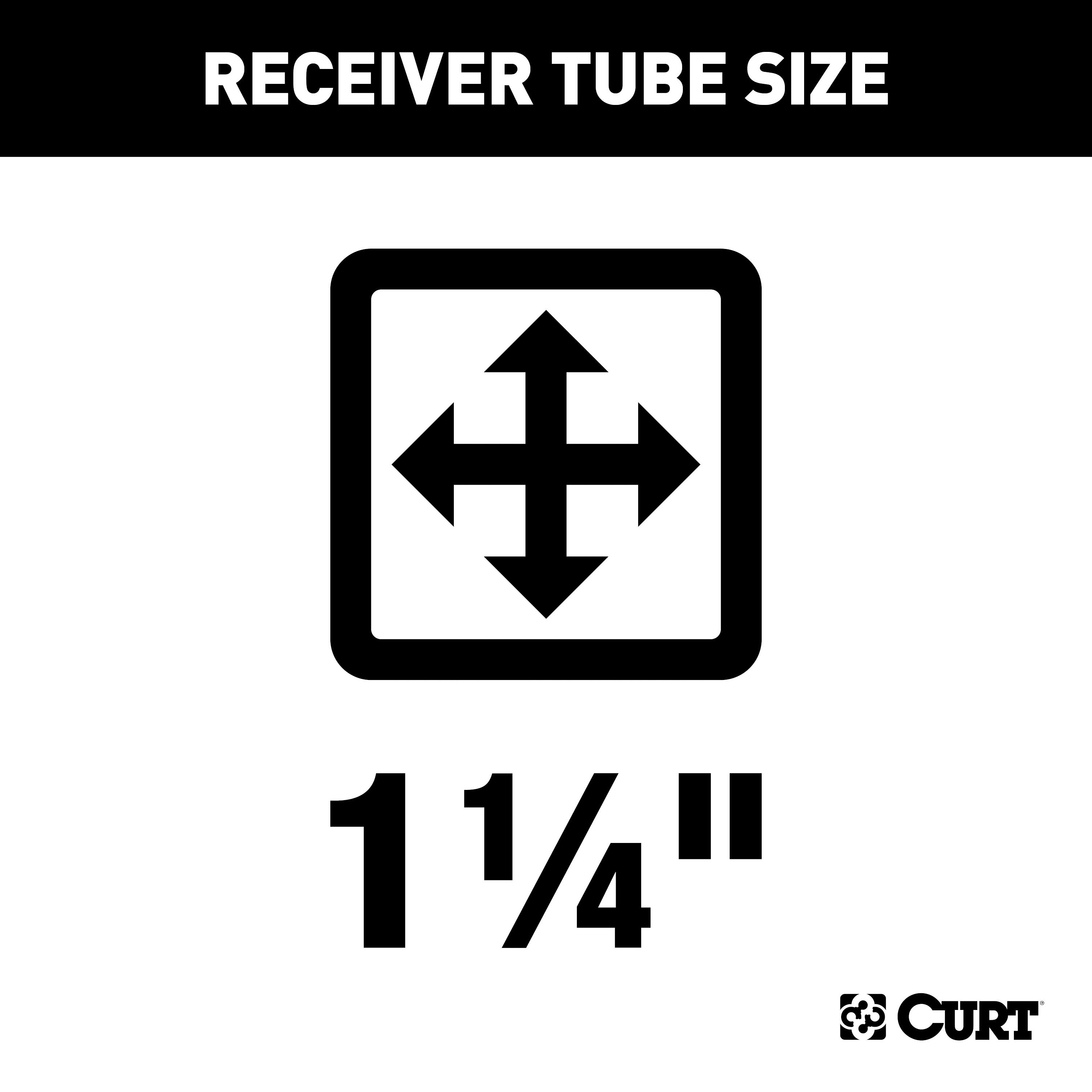
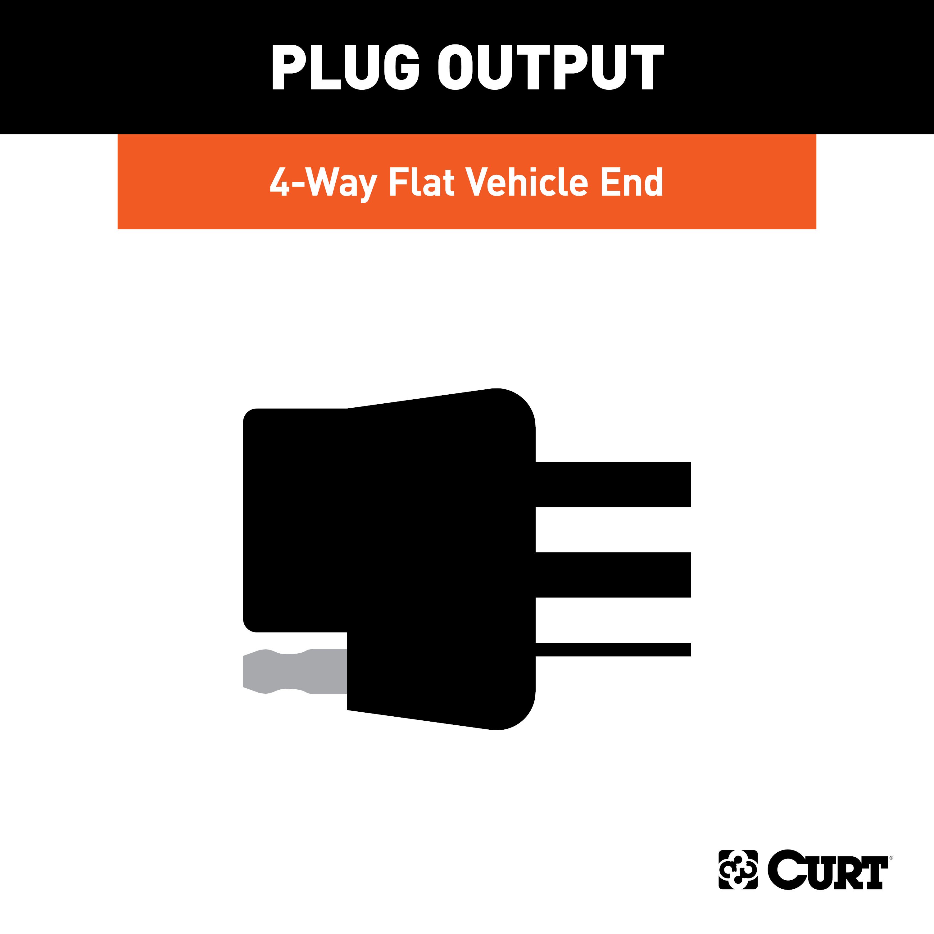
For 2005-2009 Subaru Outback Trailer Hitch + Wiring 4 Pin Fits Wagon Sport Curt 12284 59236 1-1/4 Tow Receiver Install Notes
Installation Instructions for Subaru Legacy Sedan & Wagon / Outback Sedan & Wagon (2.5 XT & 3.0 LL Bean)
Excluding Outback Sport
Part Numbers:
- 12284
Tools Required:
- Ratchet
- Torque wrench
- 14mm socket
- 17mm socket
- 3/8" socket
- Small flat screwdriver
Step-by-Step Instructions:
-
Lower the Exhaust:
- Remove the exhaust from five hangers:
- Two hangers per muffler
- One hanger rearward of the catalytic converter
- Caution: Do not allow the exhaust to hang on its own. Use wire or straps to support it.
- If installed, remove the rear factory splash guards to allow room for the exhaust to hang.
- Remove the exhaust from five hangers:
-
Remove Forward Bolt (Wagon Models Only):
- Remove the forward-most bolt from the bracket underneath the frame rails.
-
Remove Weldnut Plugs:
- Remove the plastic plugs covering the existing weldnuts in the frame rails.
-
Install Hitch:
- Raise the hitch over the exhaust and slide it under the vehicle from the rear.
- Loosely attach the hitch using the 1/2-13 carriage bolt and hardware through the vehicle's tow loop.
-
Install Spacers (As Needed):
- Use the provided spacers to level the hitch. Spacer usage will vary depending on the vehicle application.
-
Install Frame Rail Bolts:
- Install the M10 x 1.25 x 40 hex bolts with lock washers and flat washers into the existing weldnuts in the frame rails.
-
Torque Fasteners:
- Torque the 1/2-13 bolt to 110 lb-ft.
- Torque the M10 bolts to 49 lb-ft.
-
Raise Exhaust:
- Reinstall the muffler hangers to their original positions.
Hardware List:
- 1/2-13 x 1-3/4" Carriage Bolt, Grade 8, YZ: Qty 1 (Part No. 10-10272)
- 1/2-13 Serrated Flange Nut, Grade 8, YZ: Qty 1 (Part No. 20-00062)
- M10 x 1.25 x 40 Hex Bolt, Class 10.9, YZ: Qty 4 (Part No. 10-10398)
- 7/16" Lock Washer, YZ: Qty 4 (Part No. 30-00184)
- 3/8" Flat Washer, YZ: Qty 4 (Part No. 30-00186)
- .250 x 1.50 x 3.00" Square Hole Spacer (CM-SP41): Qty 1
- .250 x 1.50 x 2.00" Round Hole Spacer (CM-SP16): Qty 2
Safety Notes:
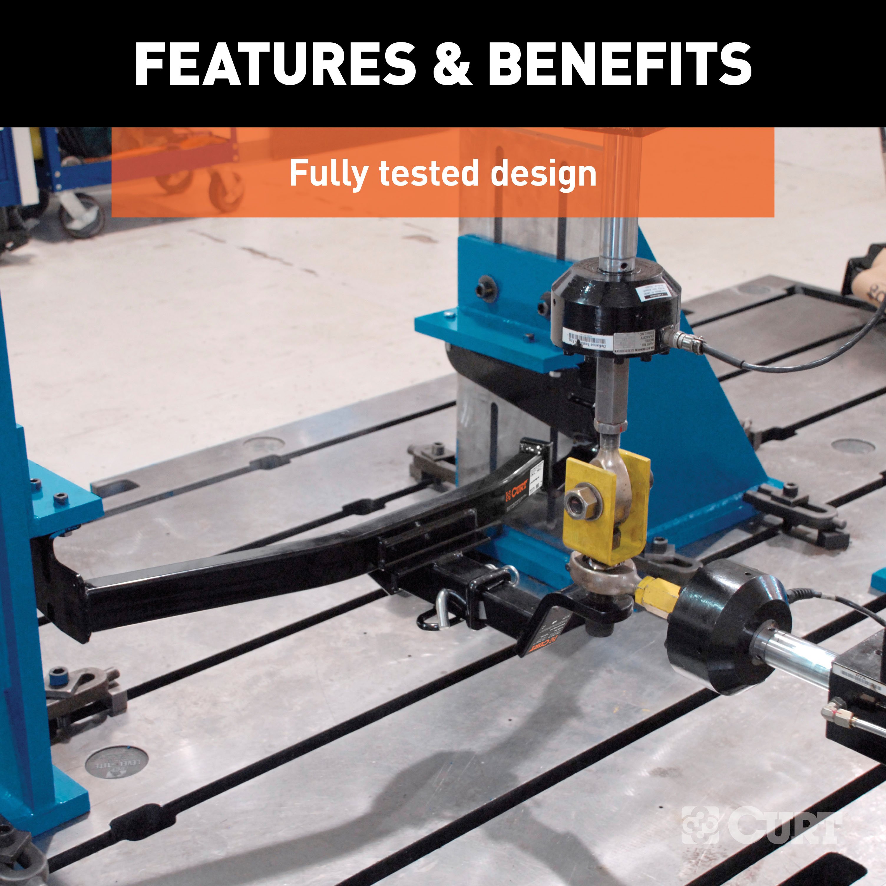
- Gross Load Capacity (Weight Carrying Hitch): 3,500 lbs (trailer weight), 300 lbs (tongue weight).
- Warning: All non-trailer loads must be supported with auxiliary stabilizing straps.
- Failure to properly support non-trailer loads will void the product warranty.
- Periodically inspect the hitch to ensure all fasteners remain tight and structural components remain sound.
Specifications:
- Installation Time:
- Professional: 27 minutes
- Novice (DIY): 35 minutes
- Drilling Required: No
- Lower Exhaust Required: Yes
- Bolt Removal Required: Yes
- Weldnut Plug Removal Required: Yes
Manufacturer Notes:
- Designed for use with Ball Mount #D-19 / 45519.
- Warranty covers defects in material and workmanship at the time of purchase.
- For technical support, call Curt Manufacturing at 1-877-287-8634.
Vehicle Applications:
- Fits Subaru Legacy Sedan & Wagon
- Fits Subaru Outback Sedan & Wagon (2.5 XT & 3.0 LL Bean)
- Excluding Outback Sport
Revision History:
- 1/9/2008: Added 2.5 XT and 3.0 LL Bean (DWS)
- 8/20/2009: Updated to current standards (JWT)
- 7/12/2012: Changed to Grade 8 torque specs (AJP)
- 6/18/2020: Updated hardware descriptions/numbers and phone numbers (CJW)
Installation Instructions for Subaru Legacy Sedan & Wagon / Outback Sedan & Wagon (2.5 XT & 3.0 LL Bean)
Excluding Outback Sport
Part Numbers:
- 12284
Tools Required:
- Ratchet
- Torque wrench
- 14mm socket
- 17mm socket
- 3/8" socket
- Small flat screwdriver
Step-by-Step Instructions:
-
Lower the Exhaust:
- Remove the exhaust from five hangers:
- Two hangers per muffler
- One hanger rearward of the catalytic converter
- Caution: Do not allow the exhaust to hang on its own. Use wire or straps to support it.
- If installed, remove the rear factory splash guards to allow room for the exhaust to hang.
- Remove the exhaust from five hangers:
-
Remove Forward Bolt (Wagon Models Only):
- Remove the forward-most bolt from the bracket underneath the frame rails.
-
Remove Weldnut Plugs:
- Remove the plastic plugs covering the existing weldnuts in the frame rails.
-
Install Hitch:
- Raise the hitch over the exhaust and slide it under the vehicle from the rear.
- Loosely attach the hitch using the 1/2-13 carriage bolt and hardware through the vehicle's tow loop.
-
Install Spacers (As Needed):
- Use the provided spacers to level the hitch. Spacer usage will vary depending on the vehicle application.
-
Install Frame Rail Bolts:
- Install the M10 x 1.25 x 40 hex bolts with lock washers and flat washers into the existing weldnuts in the frame rails.
-
Torque Fasteners:
- Torque the 1/2-13 bolt to 110 lb-ft.
- Torque the M10 bolts to 49 lb-ft.
-
Raise Exhaust:
- Reinstall the muffler hangers to their original positions.
Hardware List:
- 1/2-13 x 1-3/4" Carriage Bolt, Grade 8, YZ: Qty 1
- 1/2-13 Serrated Flange Nut, Grade 8, YZ: Qty 1
- M10 x 1.25 x 40 Hex Bolt, Class 10.9, YZ: Qty 4
- 7/16" Lock Washer, YZ: Qty 4
- 3/8" Flat Washer, YZ: Qty 4
- .250 x 1.50 x 3.00" Square Hole Spacer (CM-SP41): Qty 1
- .250 x 1.50 x 2.00" Round Hole Spacer (CM-SP16): Qty 2
Safety Notes:
- Gross Load Capacity (Weight Carrying Hitch): 3,500 lbs (trailer weight), 300 lbs (tongue weight).
- Warning: All non-trailer loads must be supported with auxiliary stabilizing straps.
- Failure to properly support non-trailer loads will void the product warranty.
- Periodically inspect the hitch to ensure all fasteners remain tight and structural components remain sound.
Specifications:
- Installation Time:
- Professional: 27 minutes
- Novice (DIY): 35 minutes
- Drilling Required: No
- Lower Exhaust Required: Yes
- Bolt Removal Required: Yes
- Weldnut Plug Removal Required: Yes
Manufacturer Notes:
- Designed for use with Ball Mount #D-19 / 45519.
- Warranty covers defects in material and workmanship at the time of purchase.
- For technical support and assistance, our team of experts is available to help. You can reach our tech support by visiting www.trailerjacks.com or calling 877-869-6690.
Vehicle Applications:
- Fits Subaru Legacy Sedan & Wagon
- Fits Subaru Outback Sedan & Wagon (2.5 XT & 3.0 LL Bean)
- Excluding Outback Sport
Revision History:
- 1/9/2008: Added 2.5 XT and 3.0 LL Bean (DWS)
- 8/20/2009: Updated to current standards (JWT)
- 7/12/2012: Changed to Grade 8 torque specs (AJP)
- 6/18/2020: Updated hardware descriptions/numbers and phone numbers (CJW)
Installation Instructions for Wiring Harness with Powered Converter
Part Numbers:
- 59236
Wiring Access Location:
Refer to the wiring location guides based on vehicle type provided in the manual:
SUVs and Vans:
- S1: Behind driver-side taillight housing
- S2: Behind passenger-side taillight housing
- S3: Behind driver-side rear access panel
- S4: Behind passenger-side rear access panel
- S5: Behind driver-side rear bumper
- S6: Behind the center of the rear bumper
- S7: Behind passenger-side rear bumper
- S8: Under rear floor panel
Passenger Cars:
- P1: Behind driver-side taillight housing, outside of the trunk
- P2: Behind passenger-side taillight housing, outside of the trunk
- P3: Behind driver-side taillight housing, inside the trunk
- P4: Behind passenger-side taillight housing, inside the trunk
- P5: Behind driver-side rear bumper
- P6: Behind the center of the rear bumper
- P7: Behind passenger-side rear bumper
Trucks:
- T1: Behind driver-side taillight housing
- T2: Behind passenger-side taillight housing
- T3: Behind driver-side rear bumper
- T4: Behind the center of the rear bumper fascia
- T5: Behind passenger-side rear bumper
Determining Vehicle Wiring Types:
To identify the vehicle wiring type, follow these steps:
- Ensure all lights on the vehicle are off.
- Probe the taillight connectors while they remain connected to the vehicle.
- Use the following wiring descriptions to determine the vehicle type:
Wiring Types:
-
Two-Wire System:
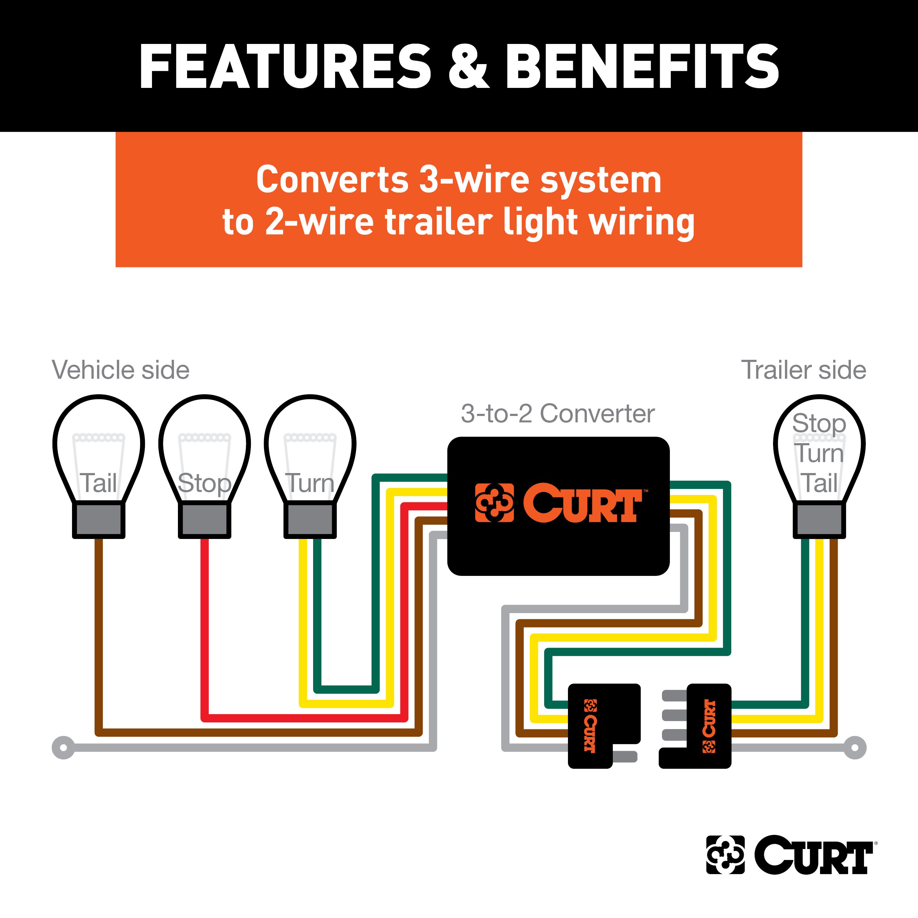
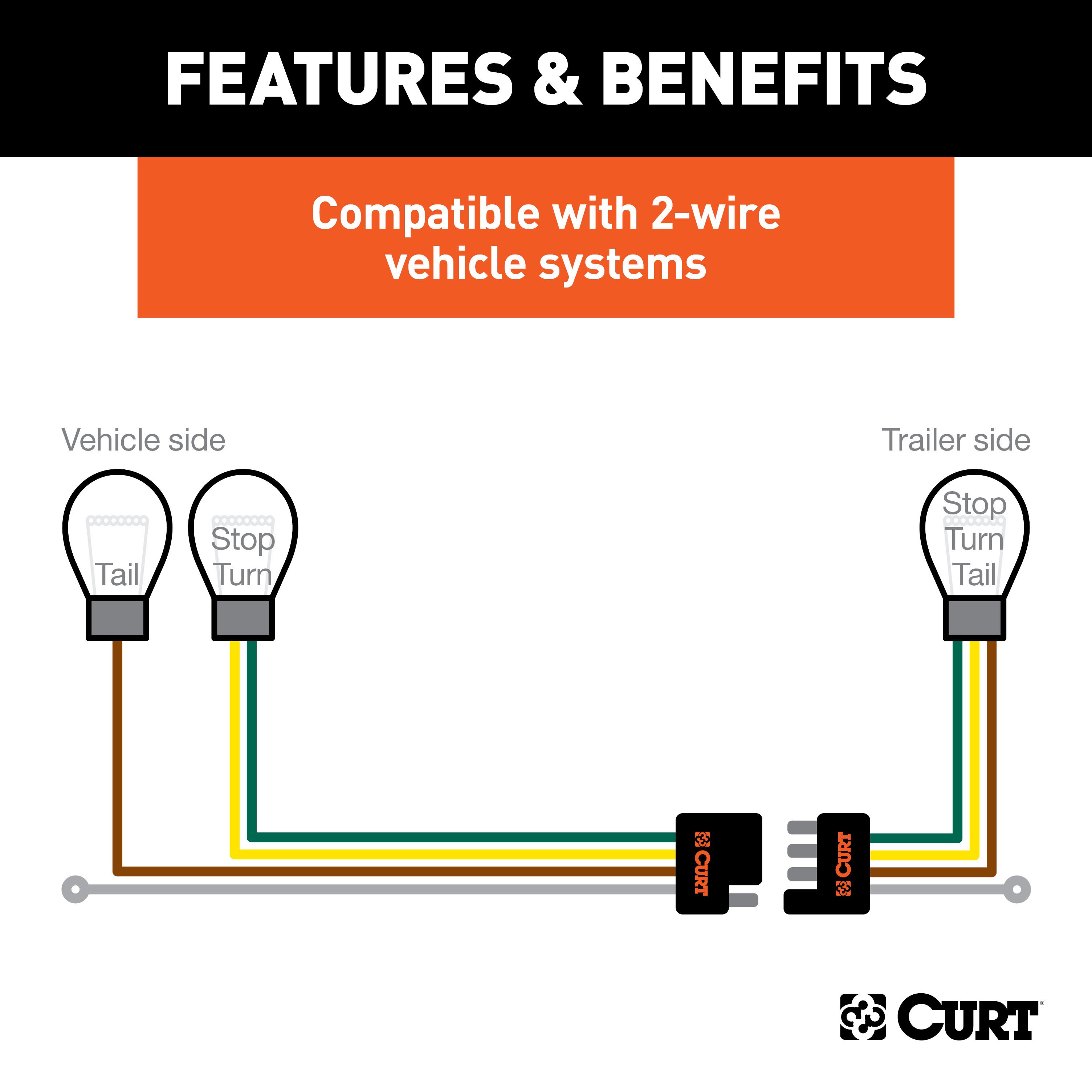
- Combined stop and turn signal with an independent tail signal.
- Indicator: Flashing signal on one side for turn signals; both sides activate for brakes.
-
Three-Wire System:
- Independent stop, turn, and tail signals.
- Indicator: Separate wires for turn signals and brake lights.
-
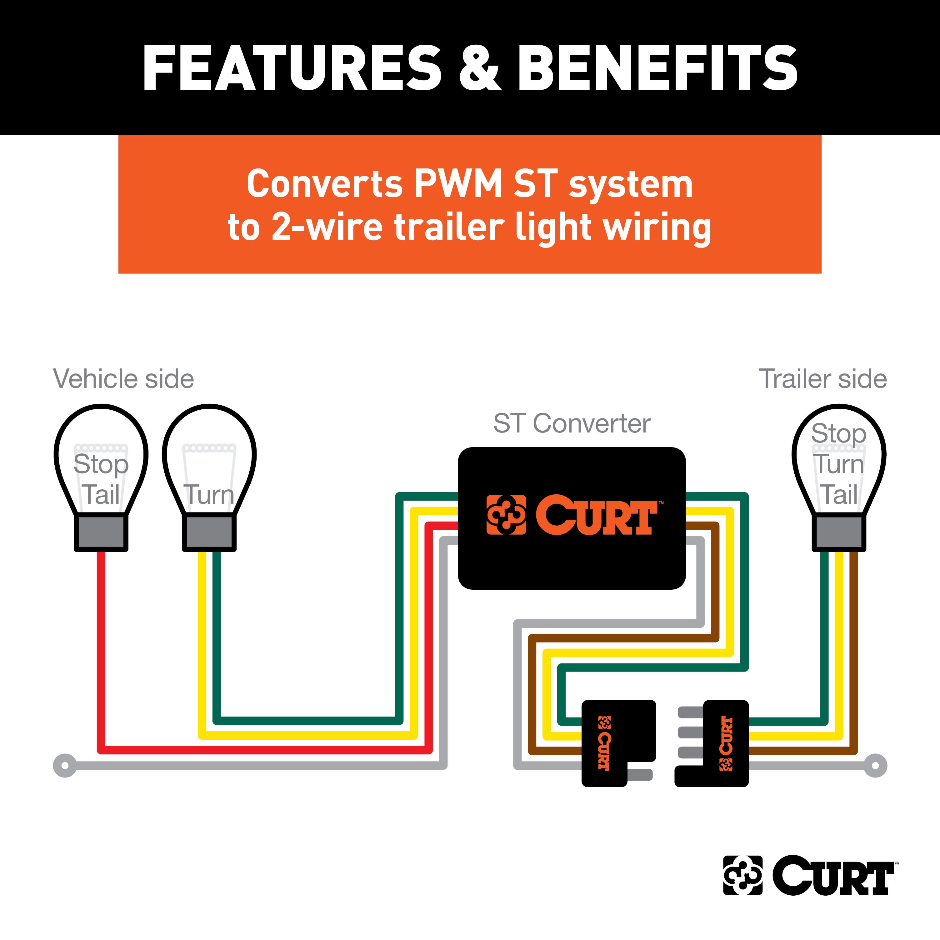
PWM-ST System:
- Combined stop and tail signal with an independent turn signal.
- Indicator: Stop and tail signals use the same wire; separate turn signal wires.
-
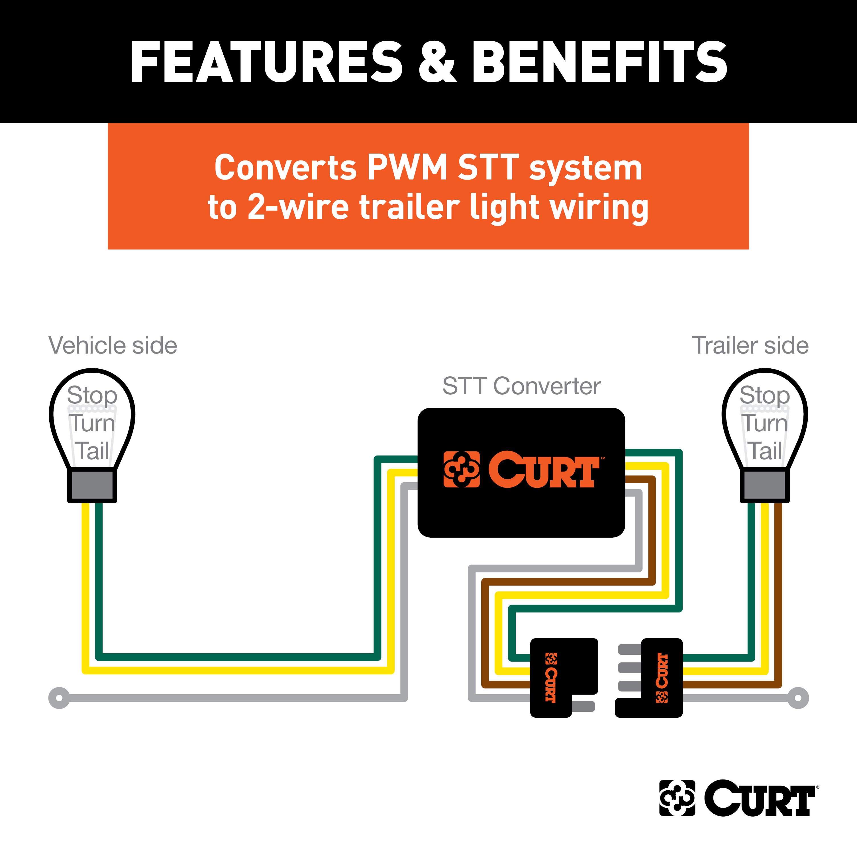
PWM-STT System:
- Combined stop, turn, and tail signal.
- Indicator: A single wire serves stop, turn, and tail functions.
Tools Required:
- Test light
- Utility knife
- Electrical tape
- Wire crimper
- Paper
- Wire stripper
- Pen
Step-by-Step Instructions:
-
Locate the Vehicle Battery
- Disconnect the negative battery terminal securely.
-
Identify Vehicle Taillight Wiring
- Use the wiring location guide and instructions for determining the wiring type.
-
Attach the Input Wires
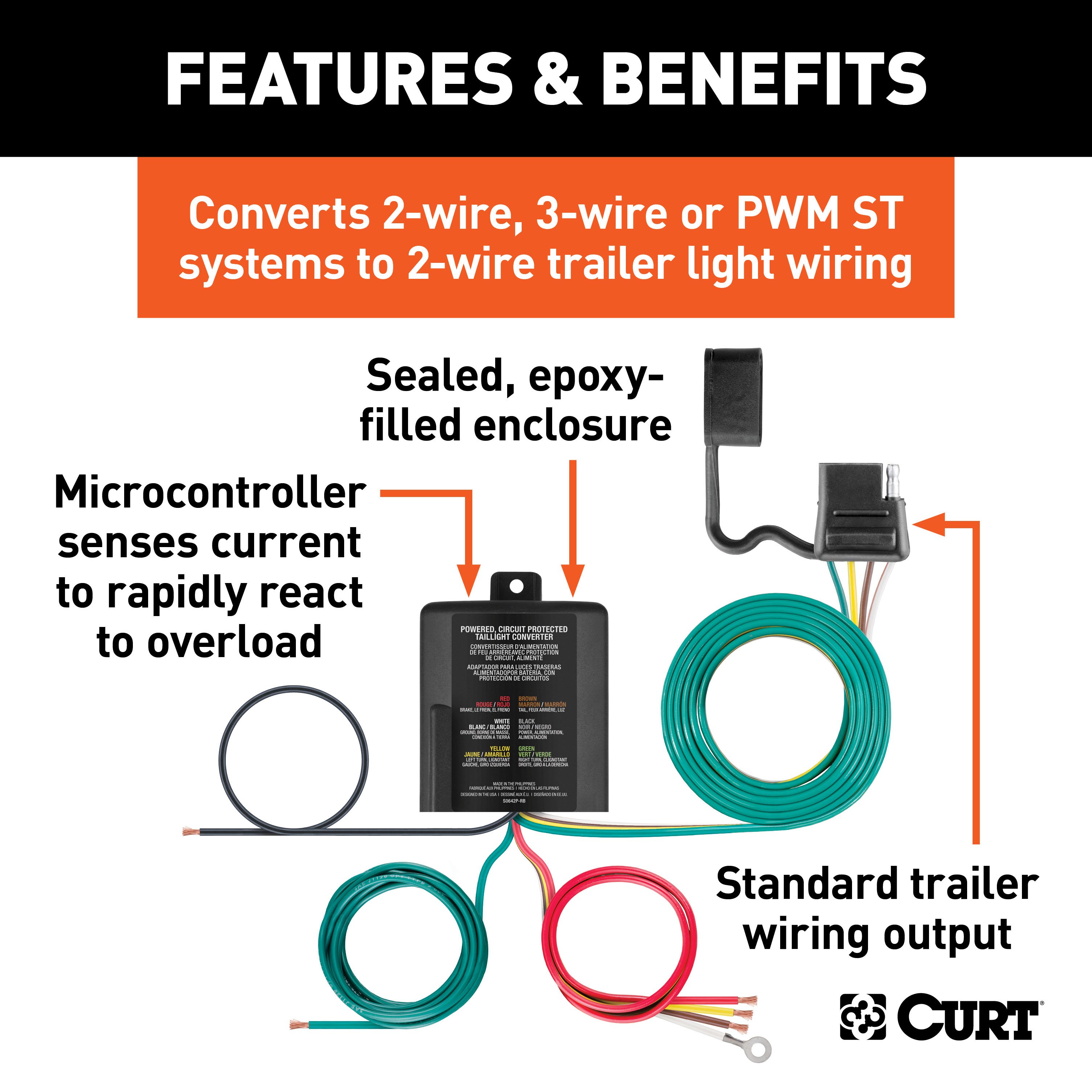
- Match wires using snap locks:
- Green Wire: Splice to the right stop/turn wire.
- Red Wire: Ground with the white wire.
- Yellow Wire: Splice to the left stop/turn wire.
- Brown Wire: Splice to the tail wire.
- Match wires using snap locks:
-
Mount the Converter
- Secure the black converter box near the taillight using the provided double-sided tape.
-
Ground the White Wire
- Use the ring terminal and provided screw to ground the wire at a clean, rust-free location.
-
Route the Power Wire
- Route the black wire to the positive battery terminal, avoiding pinch points or hot components.
-
Install the Fuse
- Add the 15-amp fuse after completing all other steps.
-
Test the System
- Verify turn signals, brake lights, and tail lights using a test light or trailer.
-
Reinstall Components
- Reinstall all removed parts and reconnect the negative battery terminal.
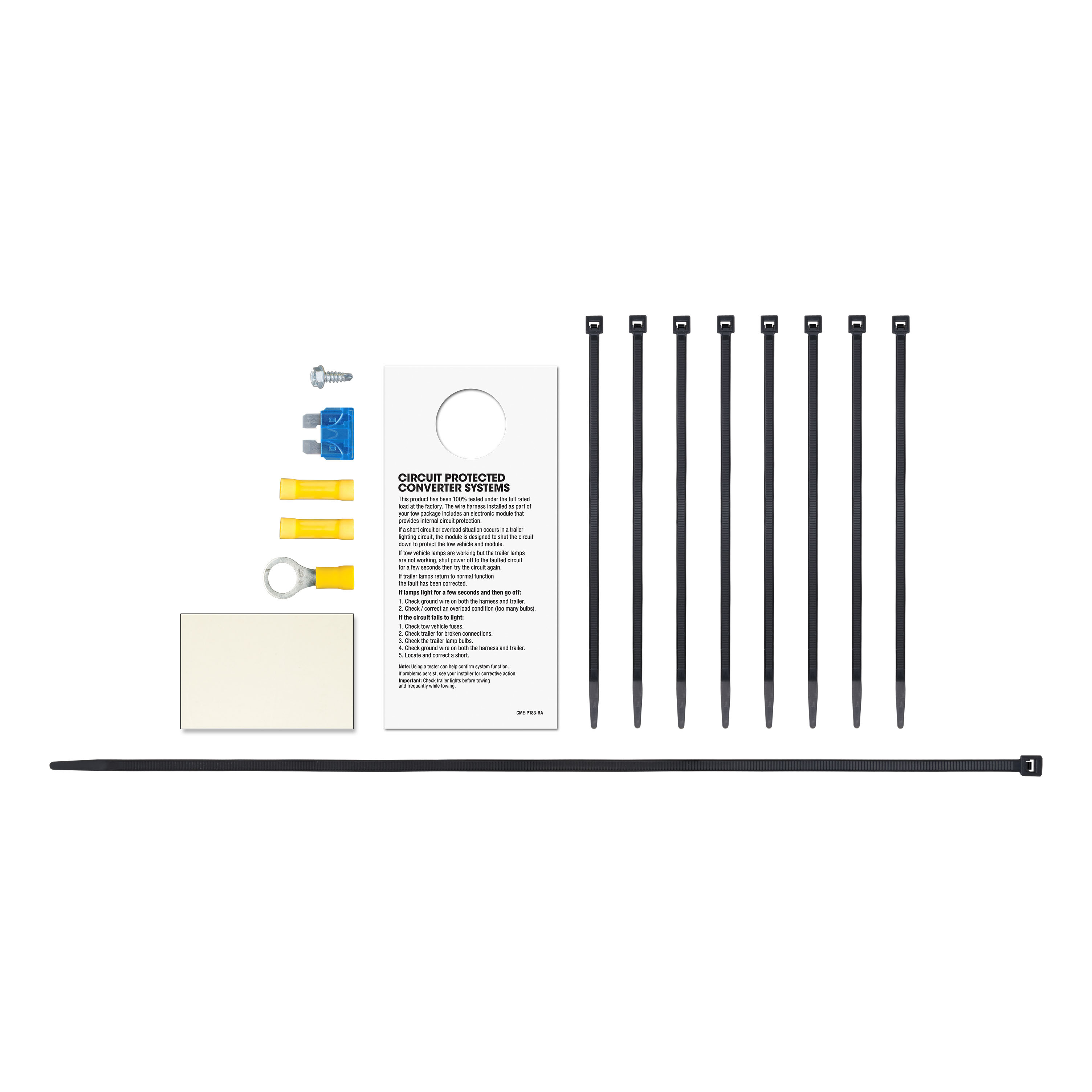
Hardware List:
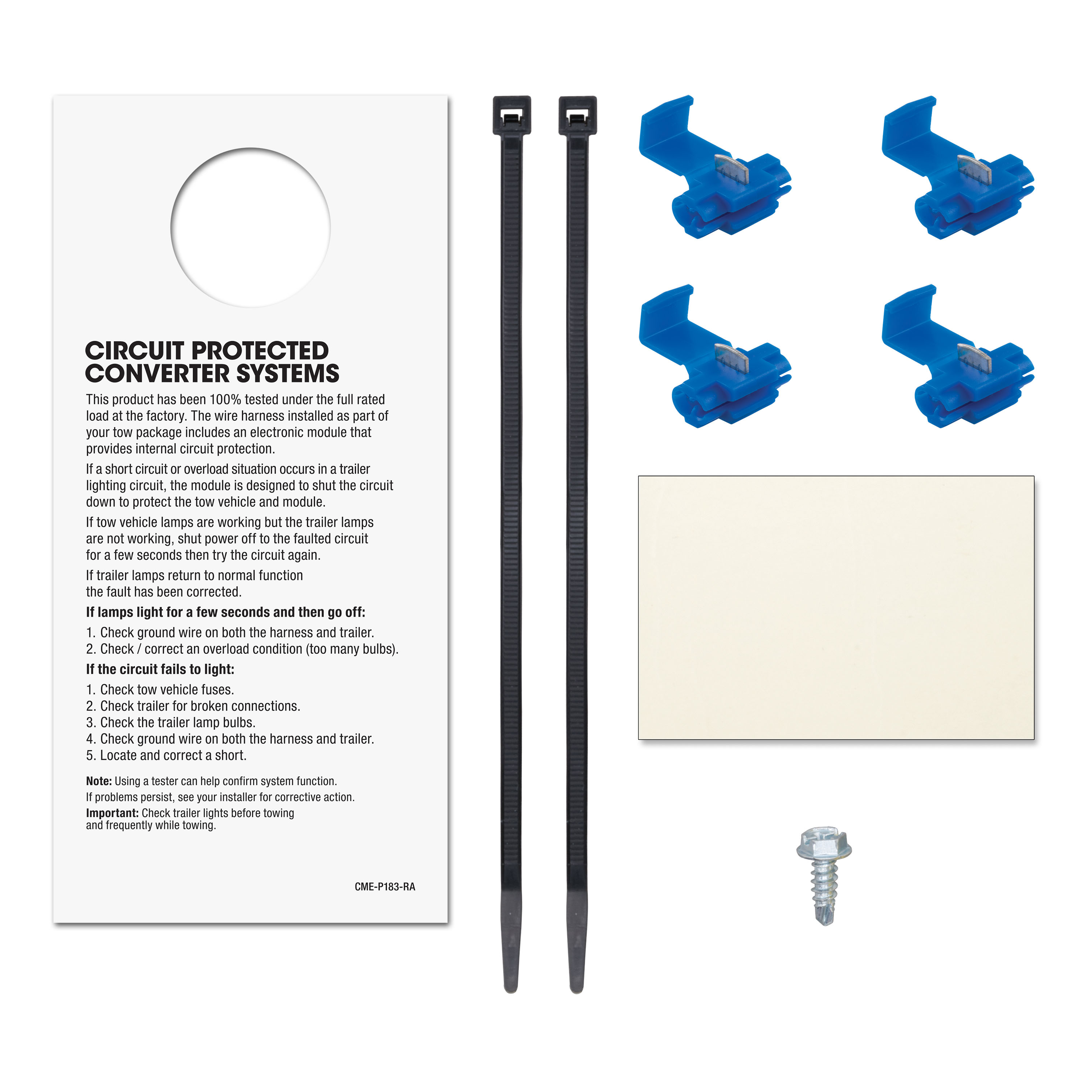
- Snap locks
- 15-amp fuse and holder
- Ring terminal
- Cable ties
- Double-sided tape
Safety Notes:
- Do not exceed product or tow vehicle lamp load ratings.
- Inspect all wiring periodically for damage or loose connections.
- Avoid drilling without confirming there are no hidden items behind the surface.
Specifications:
- Signal Circuits: 5.0-amps per side
- Tail/Running Circuits: 7.5-amps total
- Compliance: SAE J684
Additional Information:
- Attention: This is a summary of the installation procedure. For complete installation instructions, including diagrams and detailed information from the manufacturer, please download the full installation PDF.
Technical Support:
- For technical support and assistance, our team of experts is available to help. You can reach our tech support by visiting www.trailerjacks.com or calling 877-869-6690.
Warranty:
- Warranty Duration: [Insert warranty period]
- Coverage Details: [Insert coverage details]
- For complete warranty information, please download the full installation PDF.
Note: Ensure all connections are secure and test the wiring with a properly wired trailer or test light to confirm functionality.


