




For 2008-2012 Ford Escape Trailer Hitch + Wiring 4 Pin Fits All Models Curt 12060 56329 1-1/4 Tow Receiver
Model: 12060 56329-CH1213This Trailer Tow Hitch + 4-Flat Fits The Following Vehicles:
2008 - 2012 Ford Escape All Models
This Trailer Tow Hitch + 4-Flat Includes the Following Parts:
- Class 2 Hitch, 1-1/4" (Drilling Required)
- Custom Wiring, 4-Way Flat (Plug & Play)
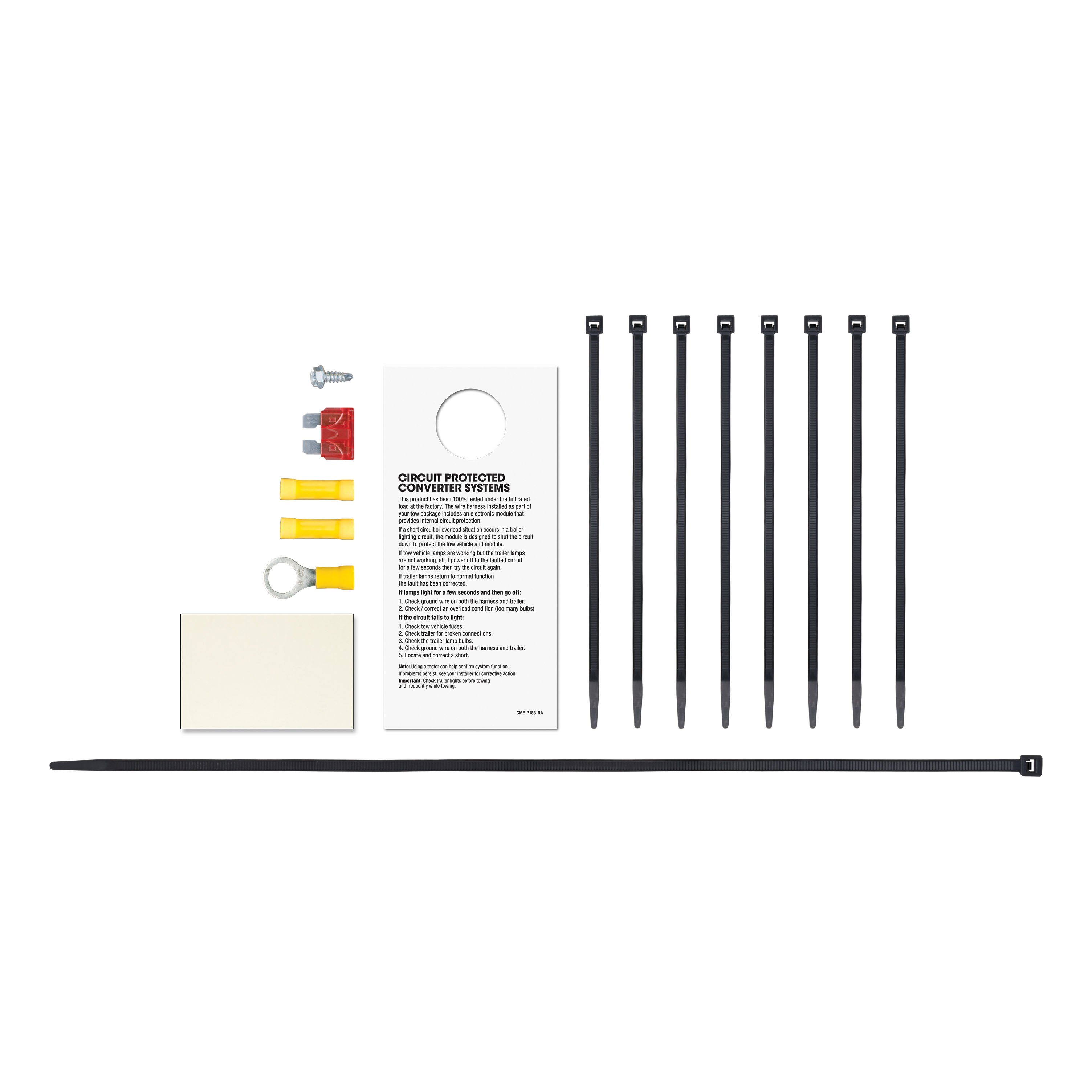
- Installation instructions, schematics, diagrams, and hardware (if required).
List of Fitment Years:
2008, 2009, 2010, 2011, 2012
CURT 12060 Class 2 Trailer Hitch, 1-1/4-Inch Receiver
Manufactured by: Curt
Whatever the next checkpoint is on your adventure -- whether it's getting your bike on the trail before sunrise or making it to the campground before dark -- CURT class 2 hitches let you Bring It with confidence These receiver hitches are made to handle most light-duty towing applications and offer a custom fit for your vehicle Typically used on full-size cars, crossovers, compact SUVs, minivans or even compact pickup trucks, a CURT class 2 trailer hitch complements the design of smaller vehicles.
This particular class 2 hitch is made to be a custom hitch for certain years of the Ford Escape, Mazda Tribute and Mercury Mariner (to verify vehicle compatibility, see application info) It offers a weight carrying capacity of 3,500 lbs GTW and 350 lbs.
TW Class 2 trailer hitches can typically be used to tow a variety of lightweight trailers, such as a small utility trailer, small fishing boat trailer or popup camper (NOTE: Never exceed the lowest weight capacity of any towing component) They are also perfect for adding cargo space to your vehicle with a bike rack or cargo carrier.
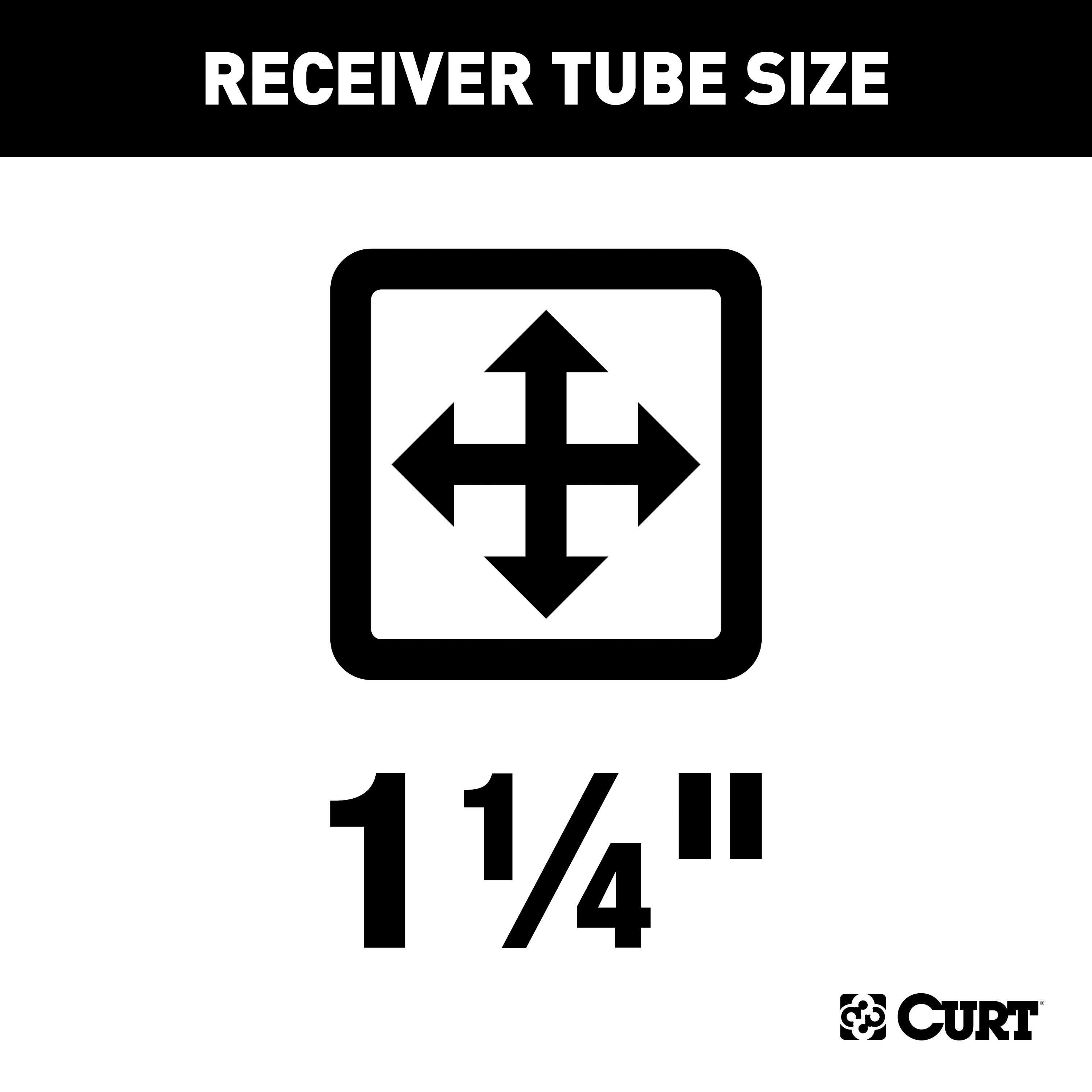
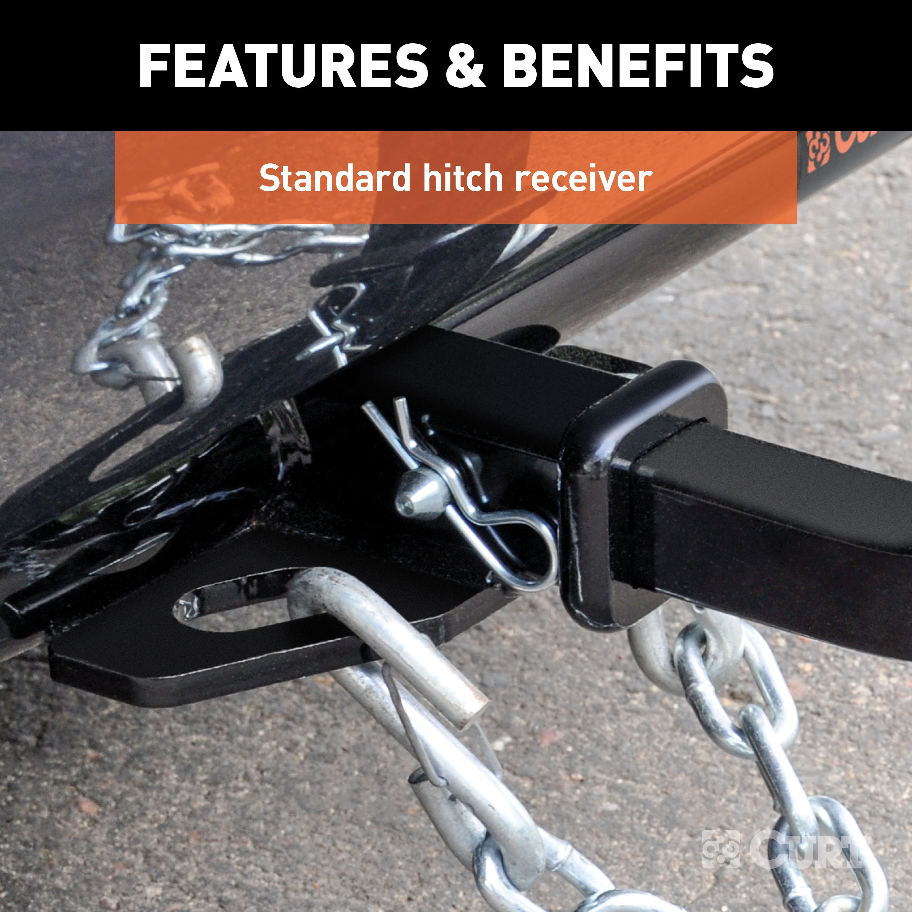
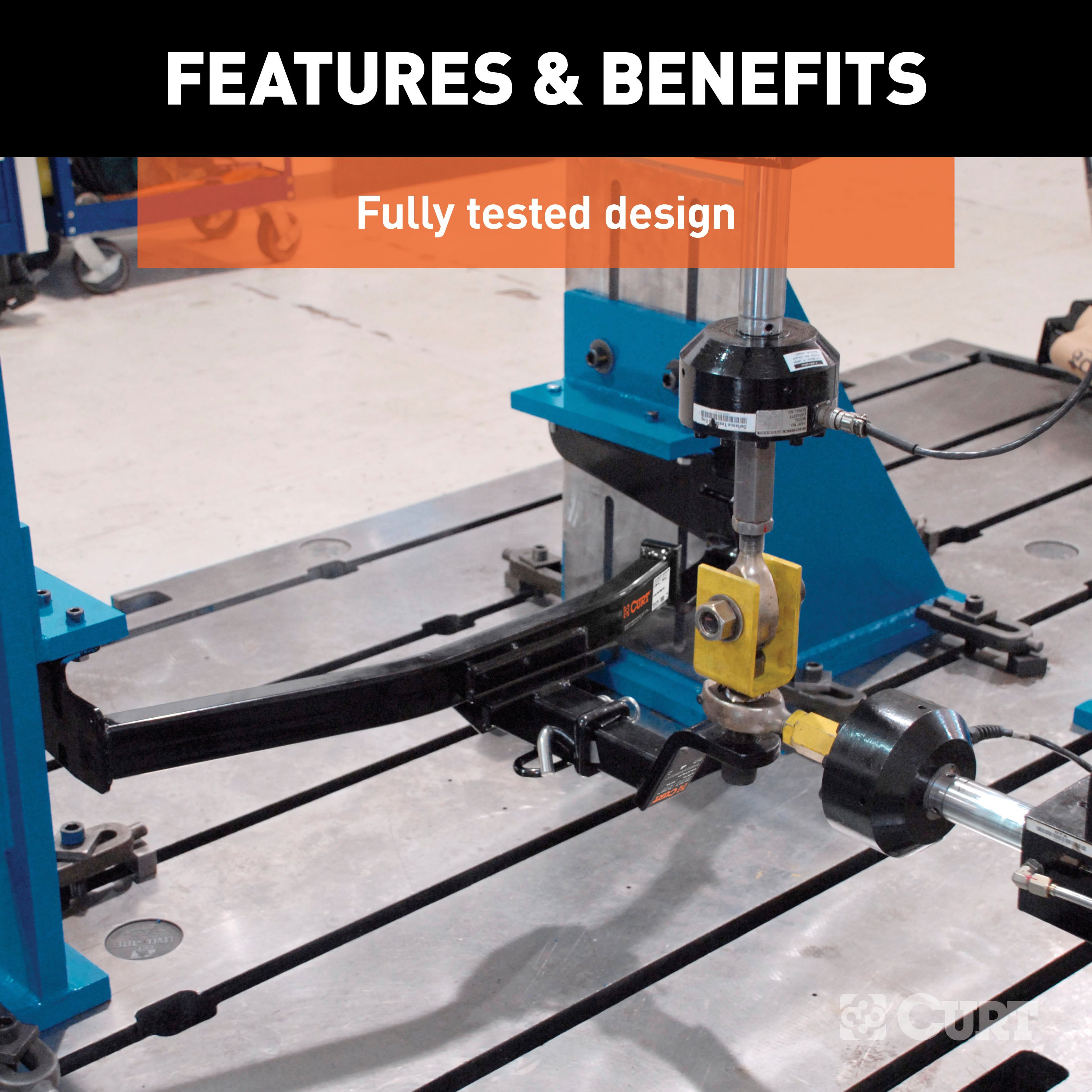
This class 2 hitch features a 1-1/4" receiver tube to accept a ball mount shank or other hitch-mounted accessory For safety, it is tested in accordance with SAE J684 A custom trailer hitch design requires extra care, and as such, CURT class 2 hitches are engineered using real vehicles and hands-on research.
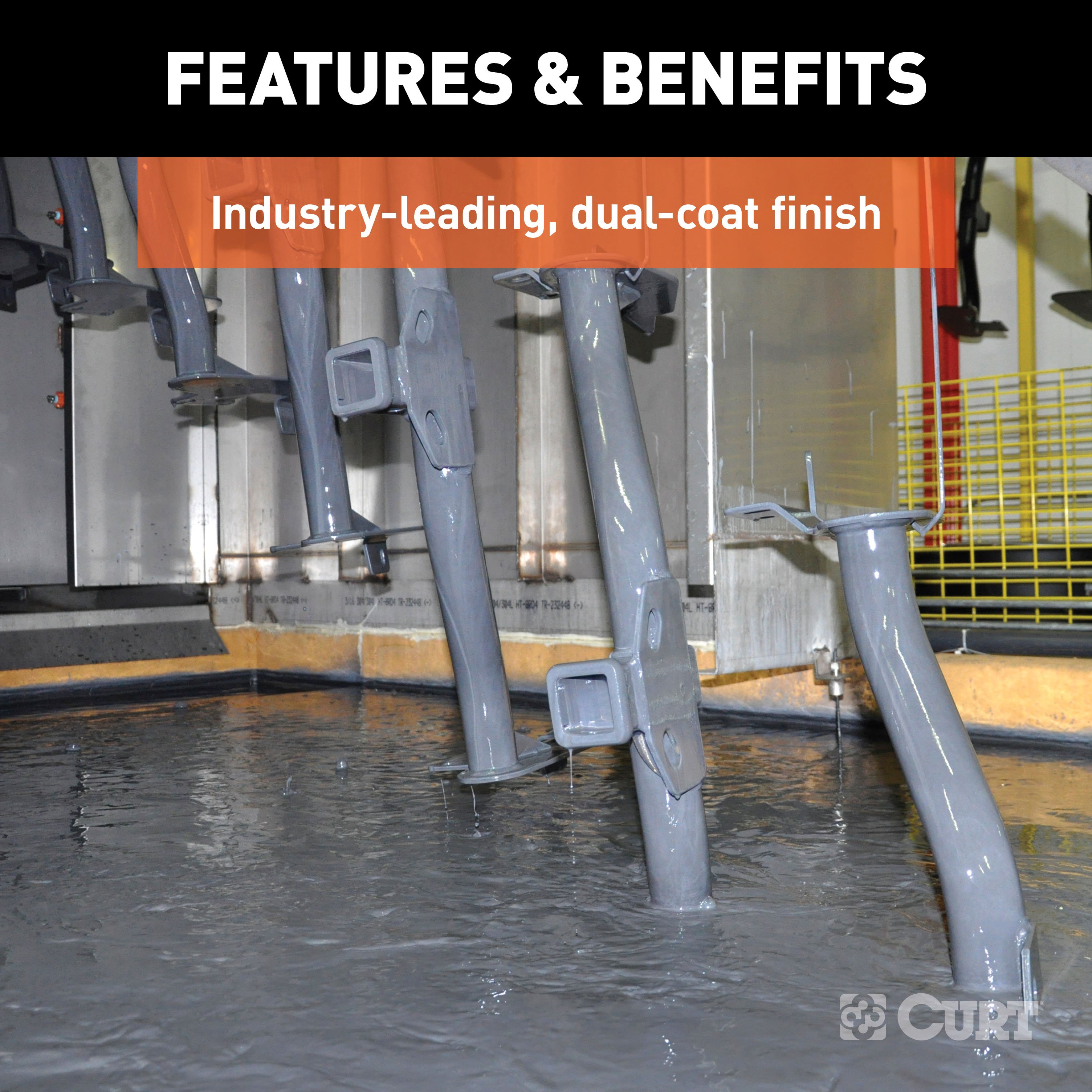
We use high-strength steel, robotic welding and rigorous testing to produce hitches that are built to fit your lifestyle To ensure that each hitch will be a reliable extension of your vehicle, we also finish our hitches in a co-curing of liquid A-coat and black powder coat, giving them long-lasting rust and wear resistance..
Features:
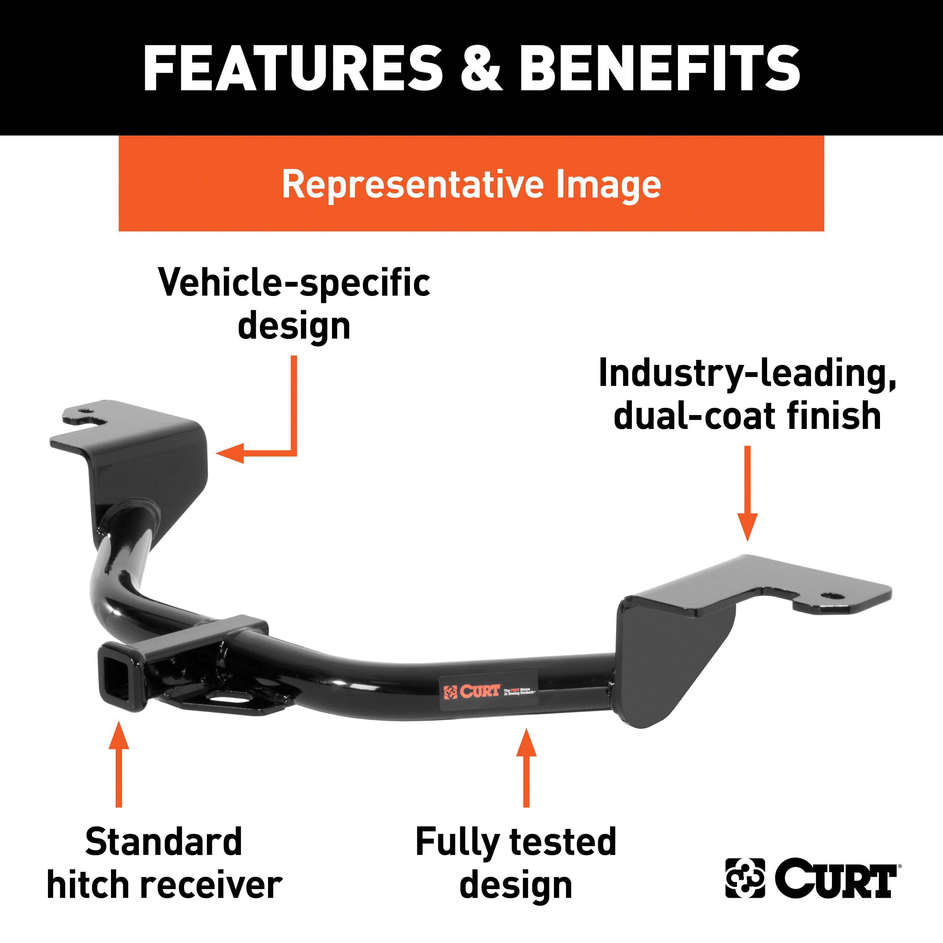
- Rated to 3,500 lbs. gross trailer weight and 350 lbs. tongue weight
- Engineered with a vehicle-specific design for a custom fit
- Tested for safety in accordance with SAE J684
- Precisely welded for superior strength and fit
- Protected by a durable high-gloss black powder coat finish
- Co-cured in a rust-resistant liquid A-coat, inside and out
- Equipped with an open-back receiver for easy cleaning
- Limited lifetime warranty (one-year finish, one-year parts)
- Made in USA (may include imported hardware)
CURT 56329 Vehicle-Side Custom 4-Pin Trailer Wiring Harness
Manufactured by: Curt
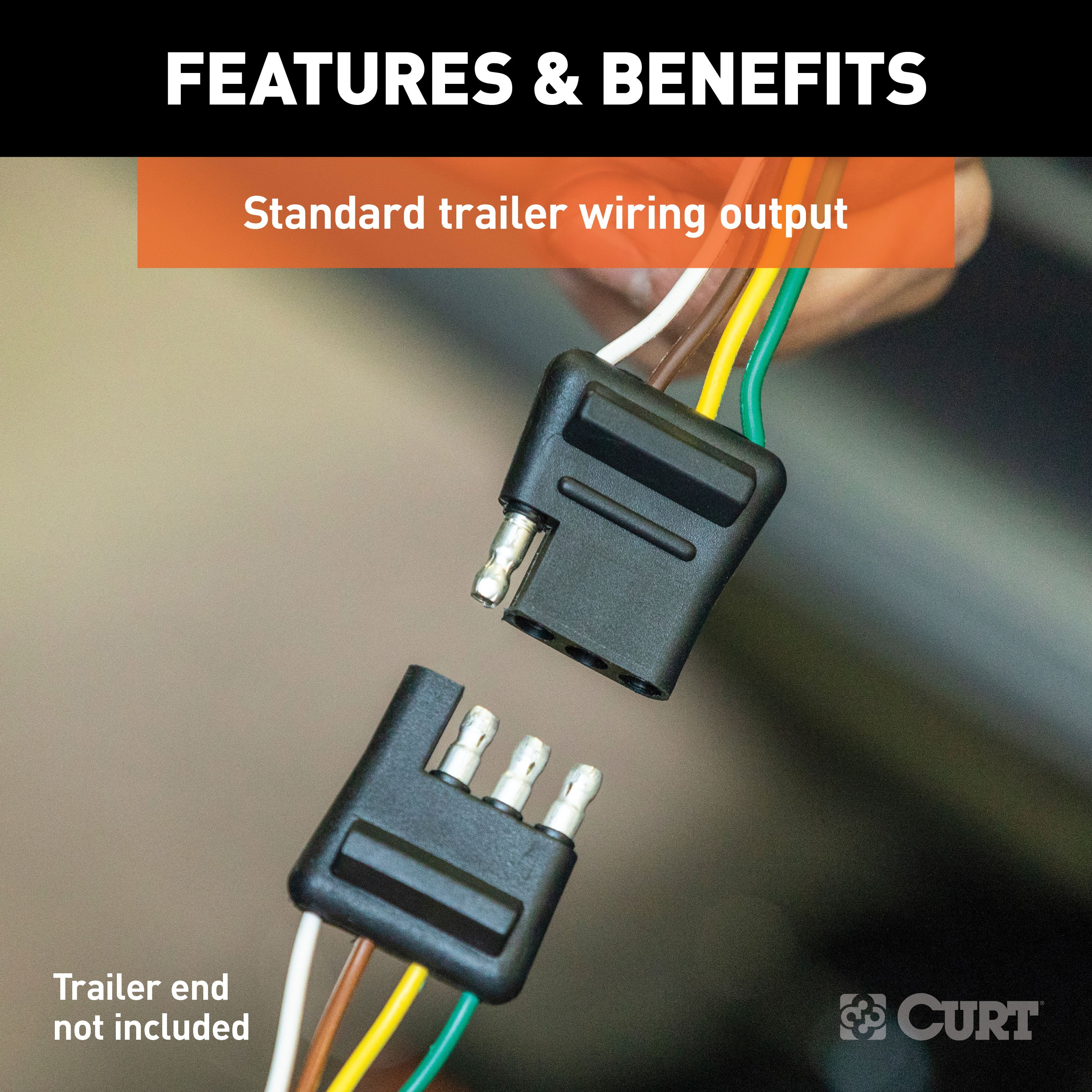
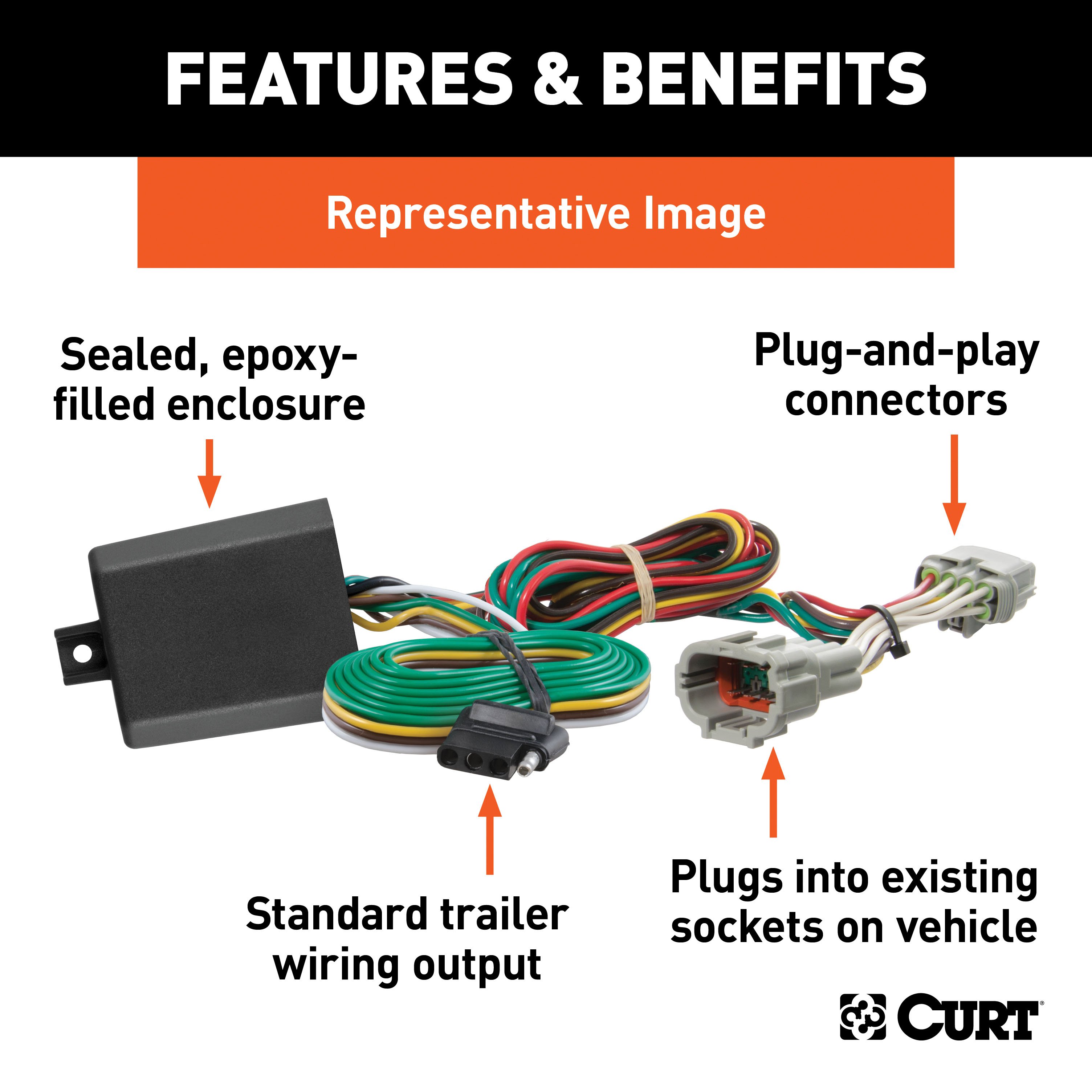
If your vehicle is not equipped with wiring for towing a trailer, CURT custom wiring is the ideal solution A custom wiring harness -- also called a T-connector -- is a simple, plug-and-play electrical device that plugs into your automotive electric system and provides a standard, universal trailer wiring connection This is done using two or more vehicle-specific, OEM-compatible connectors to plug into the taillight assembly, eliminating the need for cutting, splicing and soldering during installation.
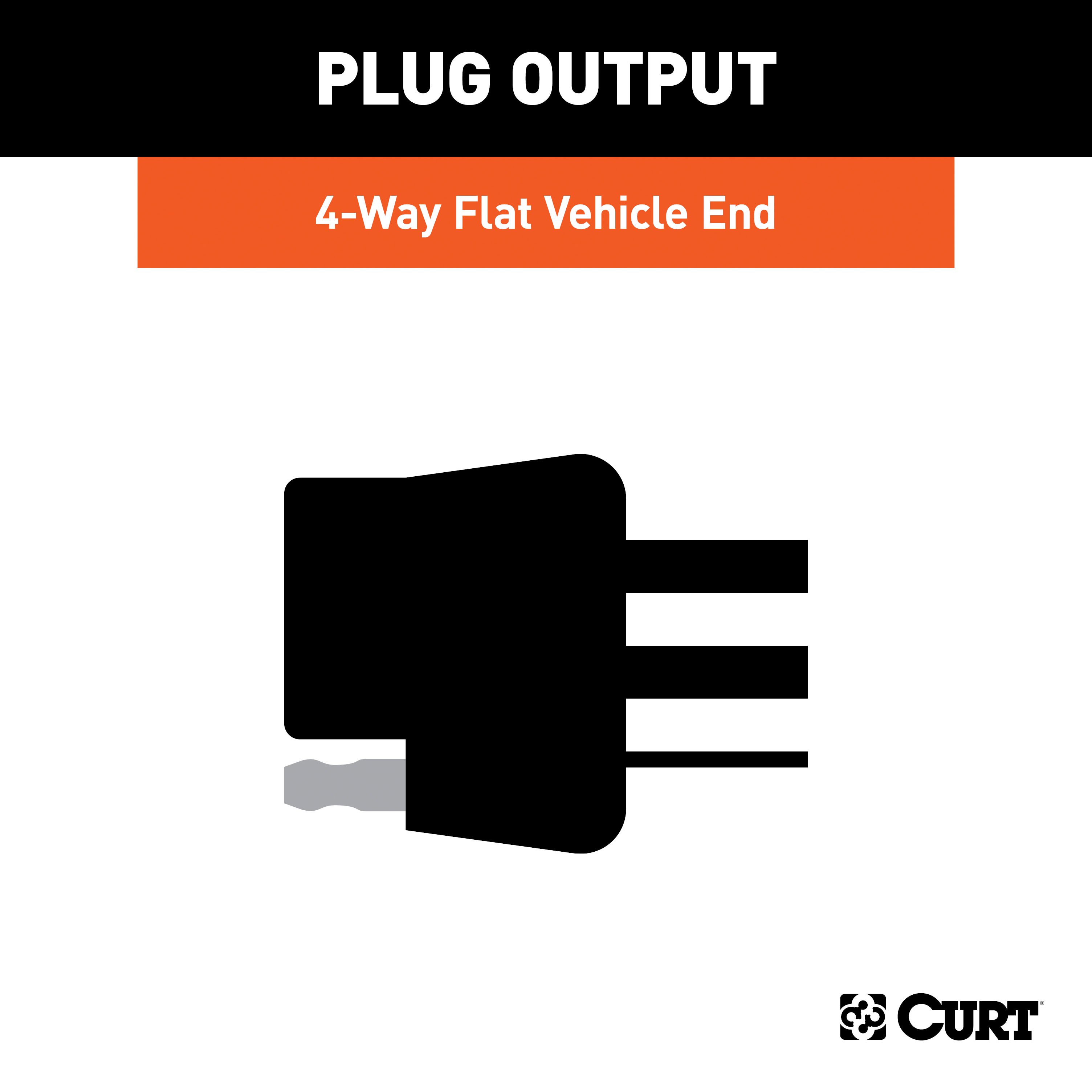
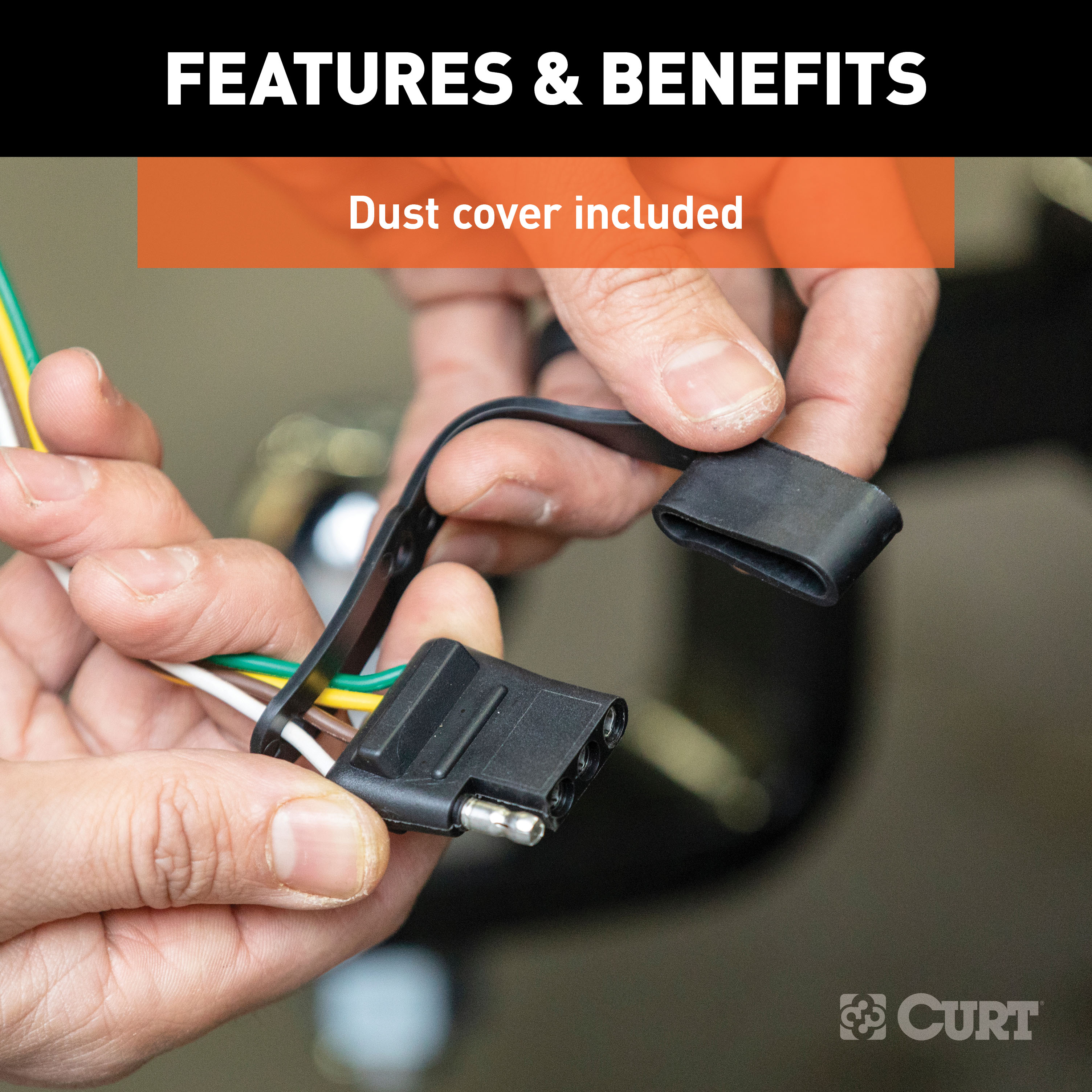
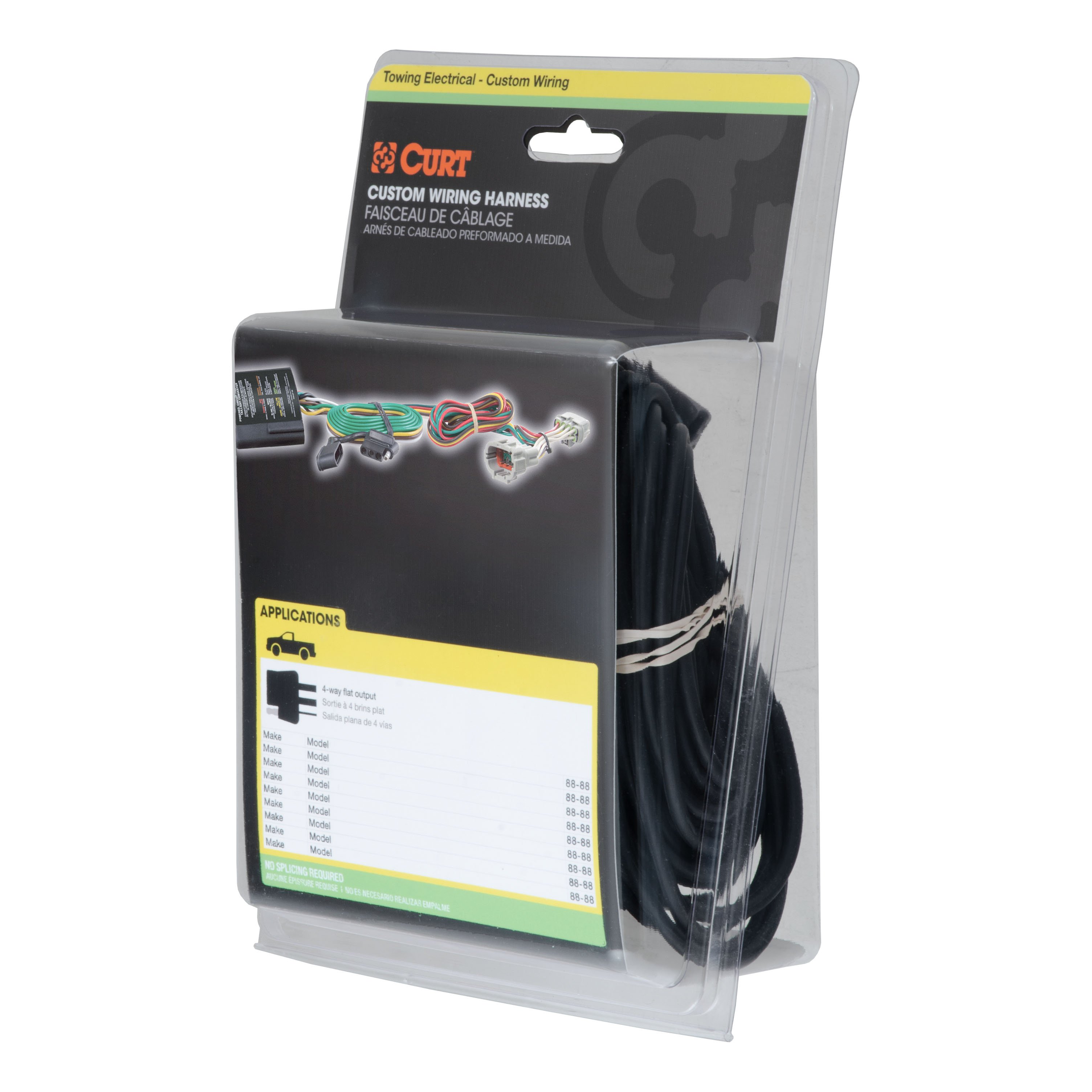
Custom wiring harnesses are made vehicle-specific, and while they are not available for all vehicles, they do offer one of the fastest, easiest and most secure ways to wire a vehicle for towing This particular plug-in harness provides a 4-way flat connector socket and is designed to be a custom wiring harness to fit certain years of the Ford Edge, Ford Escape, Ford Freestar, Lincoln MKX, Mazda Tribute and Mercury Mariner (to verify your vehicle compatibility, see application info) It comes with all necessary wiring components to establish a reliable trailer wiring connection, as well as a dust cover to keep the connector clean when not in use.
You have a picture in mind of your next destination -- maybe it's the boat landing at your favorite fishing spot, maybe it's a campsite that overlooks one of nature's masterpieces, or maybe it's the next big jobsite However, turning that picture into a reality takes more than just daydreaming It takes a solid connection and the right amount of power.
CURT custom wiring is made with some of the most sophisticated technology in the industry and is designed to install with ease, giving you a long-lasting electrical connection for your towing hitch setup..
Features:
- Plugs into vehicle tail light assembly to provide a 4-way flat socket
- Simple plug-and-play design eliminates the need for cutting or splicing
- 4-way flat output connects tail lights, brake lights and turn signals
- Equipped with tail light converter for vehicle-trailer compatibility
- Constructed with SMT circuitry for better performance and durability
- Dust cover included to keep connector clean when not in use
- Backed by a limited one-year warranty
Hitches Near Me: We operate out of several warehouses across the country, ensuring faster delivery to your location.
$306 99 $464.90 34% OFF
- Best Price on Web Guarantee
- Fastest Shipping
- FREE Shipping
- In Stock

We match lower prices from major authorized retailers for brand-new products in original packaging, provided the item is in stock. The competing seller must be an authorized, professional retail business; offers from
individuals, auctions, peer-to-peer sites, or unauthorized sellers don’t qualify. Used, refurbished, or open-box items are excluded.
Please see our full terms for details.
Verify Fitment
View products that fit your vehicle
Fits 's with the following styles:
View products that fit your vehicle
Fits 's with the following styles:
$464.90 $306 99
 Learn more
Questions? Call our Auto Experts at (877) 869-6690
Get it now, pay later
Select installments at checkout to split your purchase into 4 interest-free payments of $ every 2 weeks.
- No fees, ever.
- No impact on your credit score.
Payment options are offered by Affirm and are subject to an eligibility check and might not be available in all states. CA Residents: Loans by Affirm Loan Services, LLC are made or arranged pursuant to a California Finance Lender license.
Installments in partnership with

Product Details
- Brand: Curt
- Model: 12060 56329-CH1213
- Includes: Class 2 Trailer Tow Hitch, Custom Wiring
Compatibility Chart
| Year Range | Make | Model | Style |
|---|
| Default | |
| UPC | 612314013654, 612314563296 |
| Item Weight | 39.000, 1.900 |
| Country of Manufacture | US |
| Main Body Shape | Round |
| Receiver Tube Size | 1-1/4 IN |
| Finish | GLOSS BLACK POWDER COAT |
| WC / TW (Pounds) | 350 LB / 3,500 LB |
| Weight Carrying Capacity (Pounds) | 3,500 LB |
| WC Tongue Weight (Pounds) | 350 LB |
| Installation Difficulty | Novice, Professional |
| Installation Time Exact (Minutes) | 30, 45 |
| Note 1 | Trailer hitch weight ratings are limited to vehicle manufacturer's stated capacities, Vehicle battery connection required |
| Note 2 | Includes installation hardware, Includes fuse holder, battery connection wiring and other necessary wiring components |
| Warranty | Limited Lifetime Warranty (One-Year Finish, One-Year Parts), One-Year Limited Warranty |
Ask a Question about For 2008-2012 Ford Escape Trailer Hitch + Wiring 4 Pin Fits All Models Curt 12060 56329 1-1/4 Tow Receiver
Be the first to ask a question.
Description
This Trailer Tow Hitch + 4-Flat Fits The Following Vehicles:
2008 - 2012 Ford Escape All Models
This Trailer Tow Hitch + 4-Flat Includes the Following Parts:
- Class 2 Hitch, 1-1/4" (Drilling Required)
- Custom Wiring, 4-Way Flat (Plug & Play)
- Installation instructions, schematics, diagrams, and hardware (if required).
List of Fitment Years:
2008, 2009, 2010, 2011, 2012
CURT 12060 Class 2 Trailer Hitch, 1-1/4-Inch Receiver
Manufactured by: Curt
Whatever the next checkpoint is on your adventure -- whether it's getting your bike on the trail before sunrise or making it to the campground before dark -- CURT class 2 hitches let you Bring It with confidence These receiver hitches are made to handle most light-duty towing applications and offer a custom fit for your vehicle Typically used on full-size cars, crossovers, compact SUVs, minivans or even compact pickup trucks, a CURT class 2 trailer hitch complements the design of smaller vehicles.
This particular class 2 hitch is made to be a custom hitch for certain years of the Ford Escape, Mazda Tribute and Mercury Mariner (to verify vehicle compatibility, see application info) It offers a weight carrying capacity of 3,500 lbs GTW and 350 lbs.
TW Class 2 trailer hitches can typically be used to tow a variety of lightweight trailers, such as a small utility trailer, small fishing boat trailer or popup camper (NOTE: Never exceed the lowest weight capacity of any towing component) They are also perfect for adding cargo space to your vehicle with a bike rack or cargo carrier.
This class 2 hitch features a 1-1/4" receiver tube to accept a ball mount shank or other hitch-mounted accessory For safety, it is tested in accordance with SAE J684 A custom trailer hitch design requires extra care, and as such, CURT class 2 hitches are engineered using real vehicles and hands-on research.
We use high-strength steel, robotic welding and rigorous testing to produce hitches that are built to fit your lifestyle To ensure that each hitch will be a reliable extension of your vehicle, we also finish our hitches in a co-curing of liquid A-coat and black powder coat, giving them long-lasting rust and wear resistance..
Features:
- Rated to 3,500 lbs. gross trailer weight and 350 lbs. tongue weight
- Engineered with a vehicle-specific design for a custom fit
- Tested for safety in accordance with SAE J684
- Precisely welded for superior strength and fit
- Protected by a durable high-gloss black powder coat finish
- Co-cured in a rust-resistant liquid A-coat, inside and out
- Equipped with an open-back receiver for easy cleaning
- Limited lifetime warranty (one-year finish, one-year parts)
- Made in USA (may include imported hardware)
CURT 56329 Vehicle-Side Custom 4-Pin Trailer Wiring Harness
Manufactured by: Curt
If your vehicle is not equipped with wiring for towing a trailer, CURT custom wiring is the ideal solution A custom wiring harness -- also called a T-connector -- is a simple, plug-and-play electrical device that plugs into your automotive electric system and provides a standard, universal trailer wiring connection This is done using two or more vehicle-specific, OEM-compatible connectors to plug into the taillight assembly, eliminating the need for cutting, splicing and soldering during installation.
Custom wiring harnesses are made vehicle-specific, and while they are not available for all vehicles, they do offer one of the fastest, easiest and most secure ways to wire a vehicle for towing This particular plug-in harness provides a 4-way flat connector socket and is designed to be a custom wiring harness to fit certain years of the Ford Edge, Ford Escape, Ford Freestar, Lincoln MKX, Mazda Tribute and Mercury Mariner (to verify your vehicle compatibility, see application info) It comes with all necessary wiring components to establish a reliable trailer wiring connection, as well as a dust cover to keep the connector clean when not in use.
You have a picture in mind of your next destination -- maybe it's the boat landing at your favorite fishing spot, maybe it's a campsite that overlooks one of nature's masterpieces, or maybe it's the next big jobsite However, turning that picture into a reality takes more than just daydreaming It takes a solid connection and the right amount of power.
CURT custom wiring is made with some of the most sophisticated technology in the industry and is designed to install with ease, giving you a long-lasting electrical connection for your towing hitch setup..
Features:
- Plugs into vehicle tail light assembly to provide a 4-way flat socket
- Simple plug-and-play design eliminates the need for cutting or splicing
- 4-way flat output connects tail lights, brake lights and turn signals
- Equipped with tail light converter for vehicle-trailer compatibility
- Constructed with SMT circuitry for better performance and durability
- Dust cover included to keep connector clean when not in use
- Backed by a limited one-year warranty
Hitches Near Me: We operate out of several warehouses across the country, ensuring faster delivery to your location.


