





For 2012-2021 Nissan NV1500 Trailer Hitch + Wiring 4 Pin Fits All Models Curt 13109 56148 2 inch Tow Receiver
Model: 13109 56148-CH3081This Trailer Tow Hitch + 4-Flat Fits The Following Vehicles:
2012 - 2021 Nissan NV1500 All Models
This Trailer Tow Hitch + 4-Flat Includes the Following Parts:
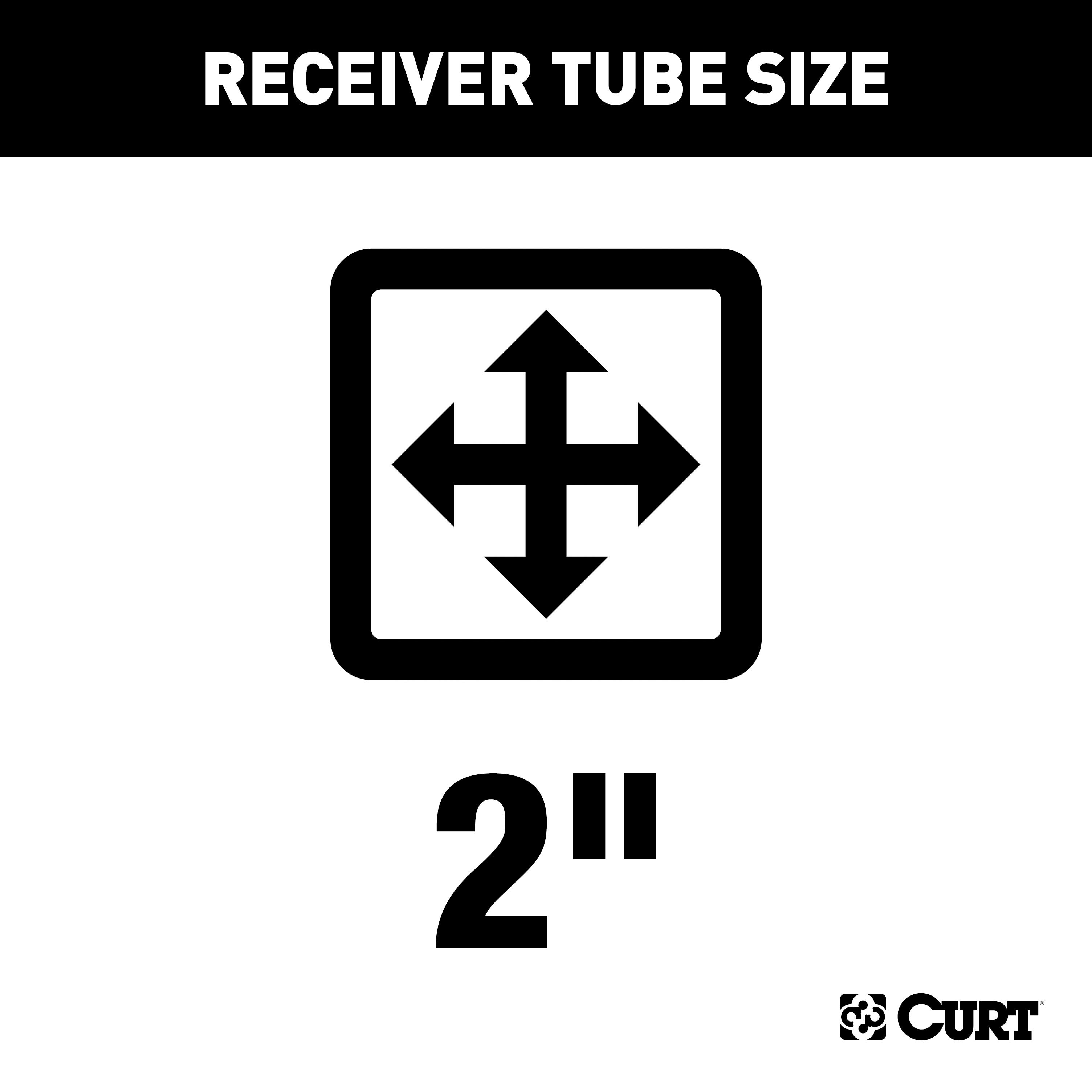
- Class 3 Trailer Hitch, 2" Receiver (Easy Bolt-On, No Drilling)
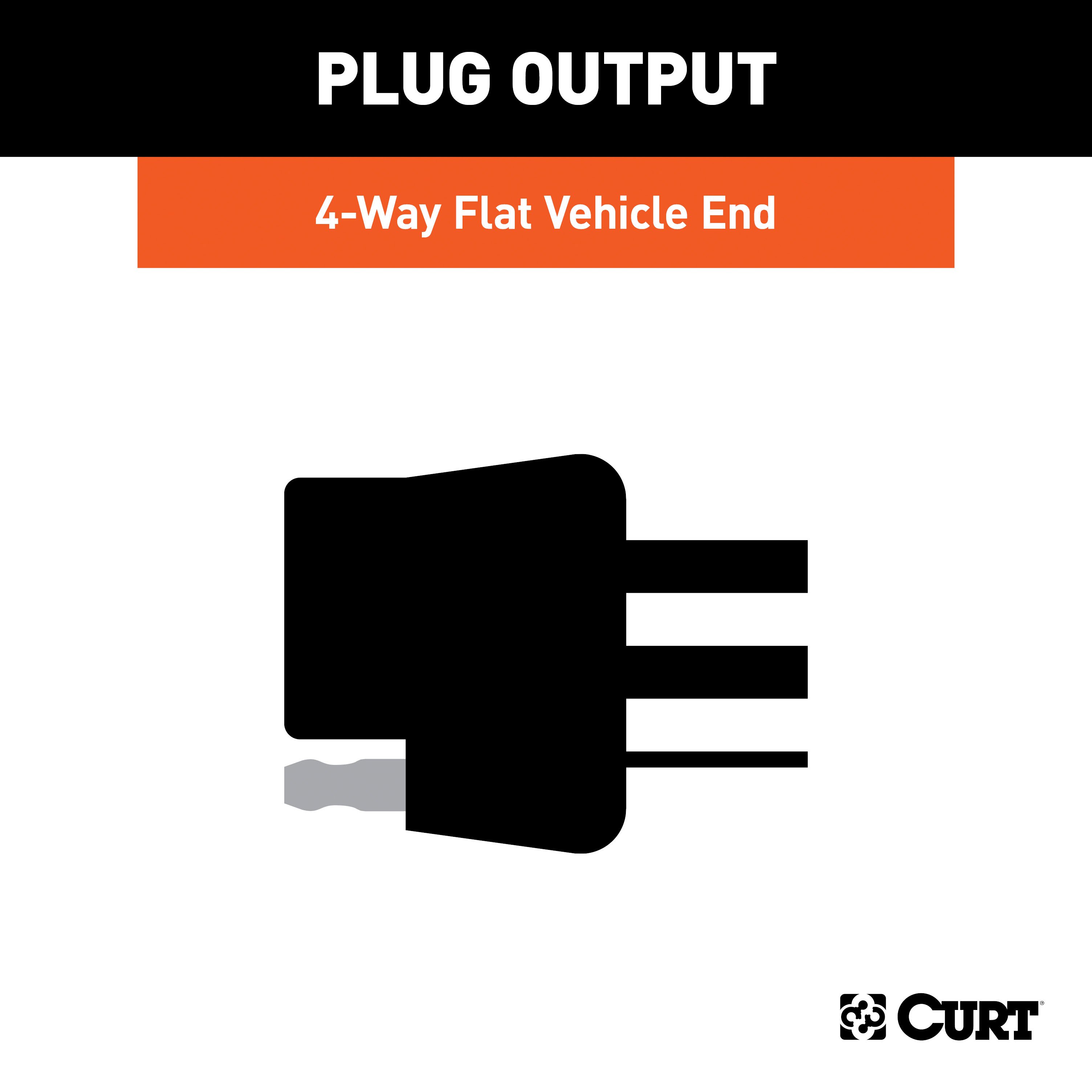
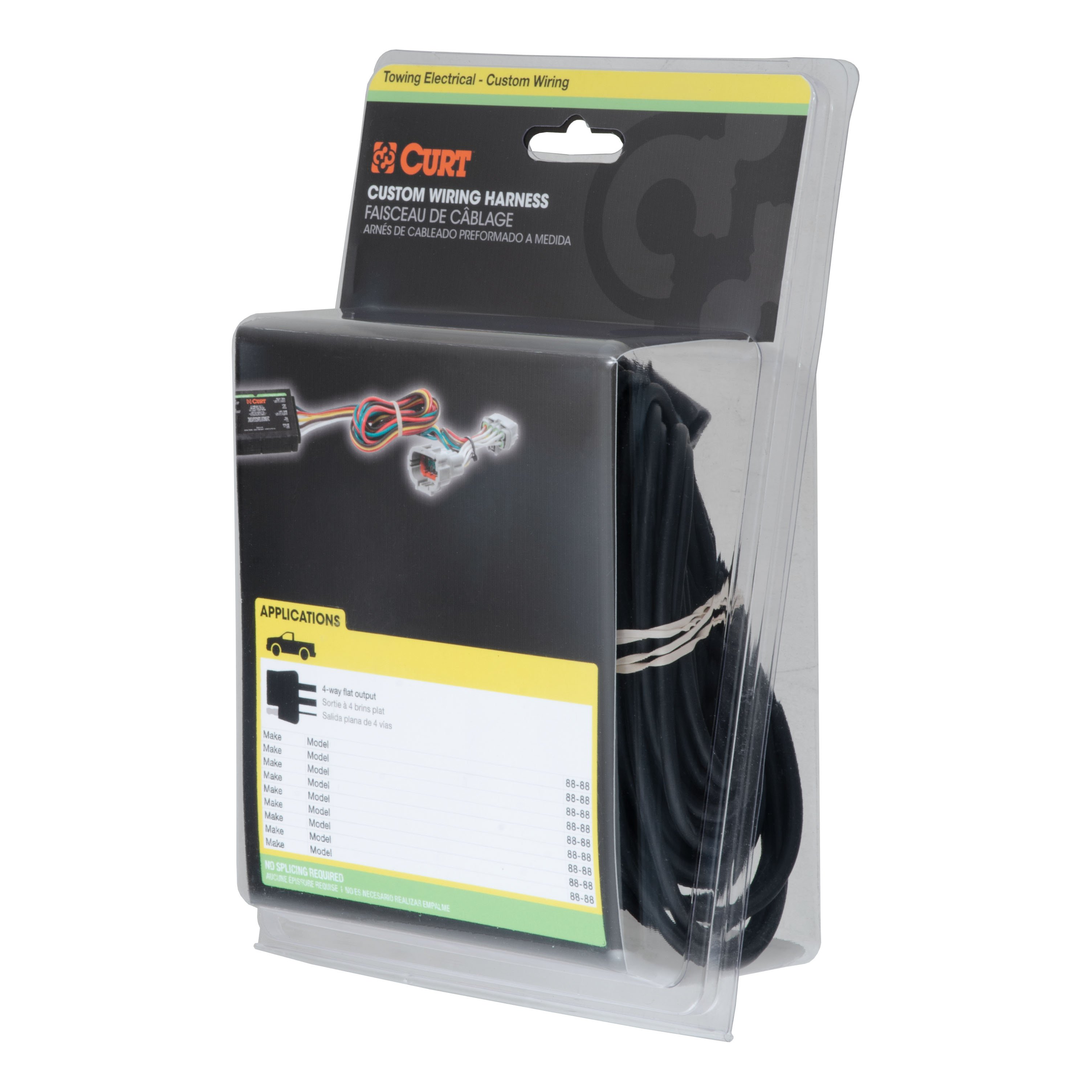
- Custom Wiring Harness, 4-Way Flat Output (Plug & Play)
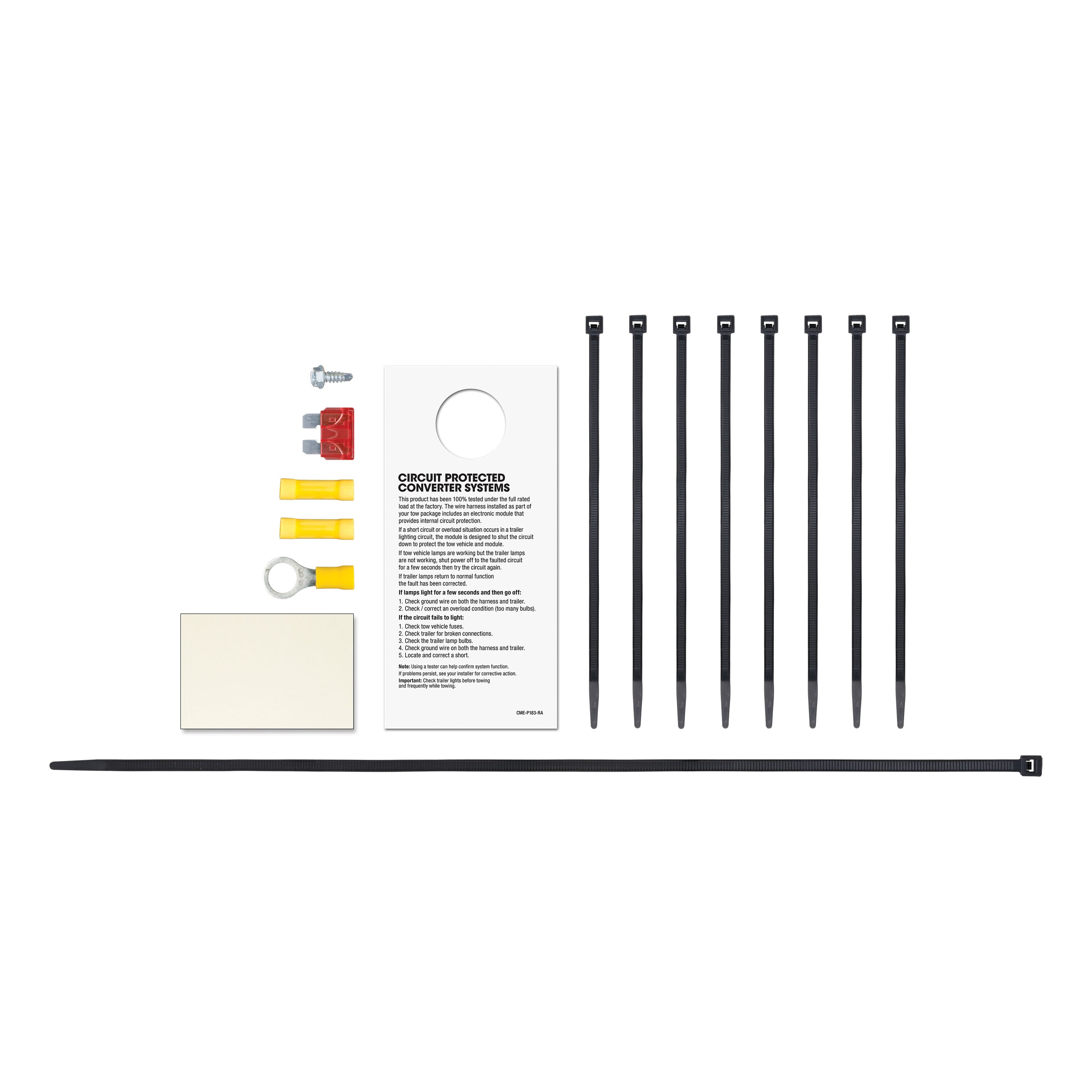
- Installation instructions, schematics, diagrams, and hardware (if required).
List of Fitment Years:
2012, 2013, 2014, 2015, 2016, 2017, 2018, 2019, 2020, 2021
CURT 13109 Class 3 Trailer Hitch, 2-Inch Receiver
Manufactured by: Curt
Whatever your task at hand -- whether it's launching that boat before daybreak, setting up your camper before the rush or getting a final load to the dump before close -- CURT class 3 trailer hitches offer the strength needed for serious towing They make it easy to hitch up and Bring It, offering a vehicle-specific fit and the weight capacity to handle a variety of trailers Custom class 3 hitches are the most common type of receiver hitch for pickup trucks and SUVs.
Because of their weight range, they are also found on full-size cars, crossovers and minivans Each custom-fit class 3 hitch package is made for vehicle-specific mounting This particular kit fits certain years of the Nissan NV1500, NV2500 and NV3500 (see application info to verify vehicle compatibility).
It provides a weight carrying capacity of 7,500 lbs GTW and 750 lbs TW.
It is also compatible with a weight distribution hitch for level towing and a rating of 10,000 lbs WD and 1,000 lbs WDTW.
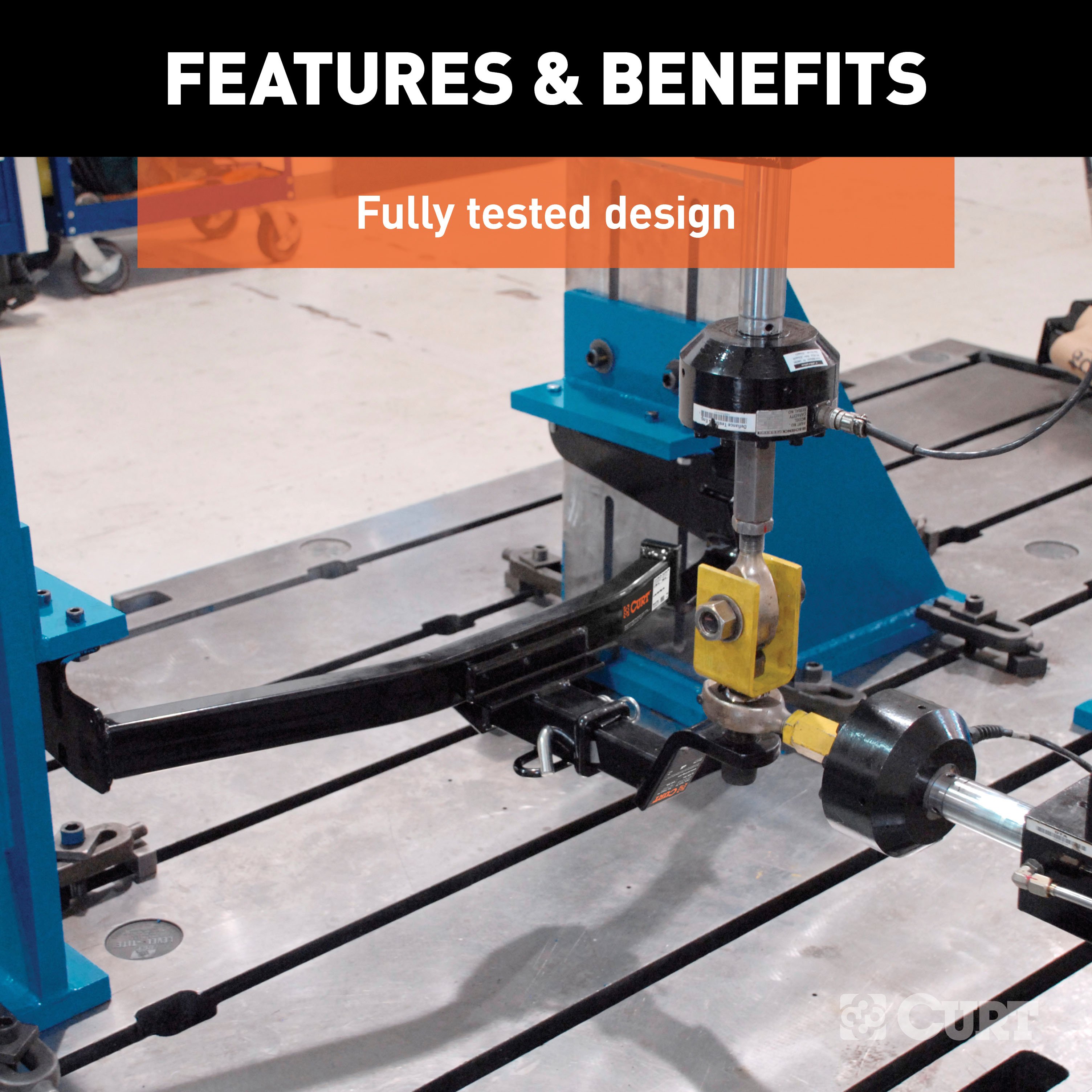
CURT class 3 trailer hitches are typically used to attach and haul utility trailers, boat trailers, campers, snowmobile or ATV haulers and more (NOTE: Never exceed the lowest-rated towing component) Each class 3 hitch has a 2" receiver tube and is tested in accordance with SAE J684 for safety To ensure that CURT class 3 receiver hitches have what it takes for serious trailering, they are designed using a hands-on approach and are constructed with rugged, high-strength steel and precise welding.
We also protect our class 3 hitches in a co-cured finish of liquid A-coat and black powder coat for superior resistance to rust, chipping and UV damage..
Features:
- Rated to 7,500 lbs. gross trailer weight and 750 lbs. tongue weight
- Compatible with weight distribution hitch (10,000 lbs. WD / 1,000 lbs. WDTW)
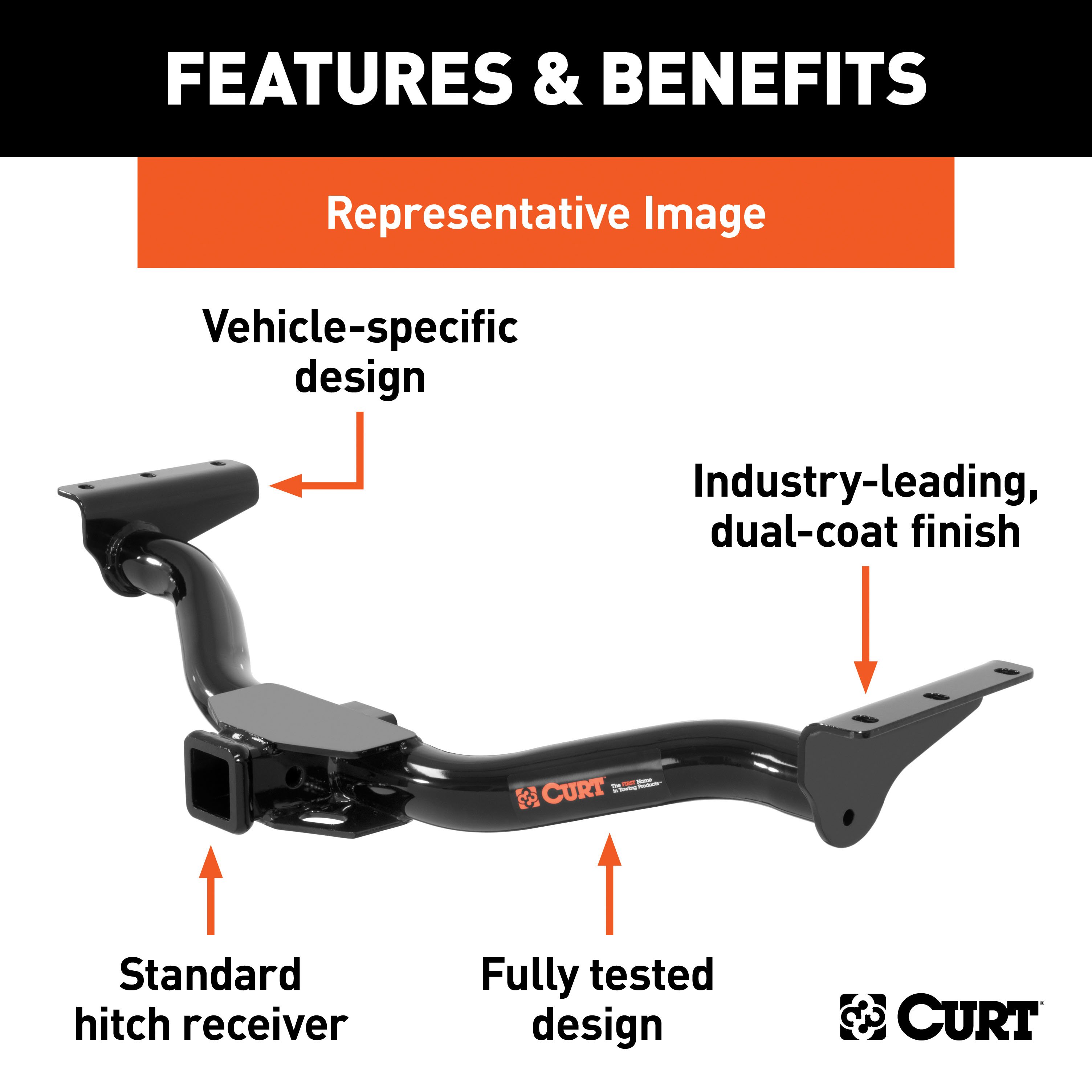
- Engineered with a vehicle-specific design for a custom fit
- Tested for safety in accordance with SAE J684
- Precisely welded for superior strength and fit
- Protected by a durable high-gloss black powder coat finish
- Co-cured in a rust-resistant liquid A-coat, inside and out
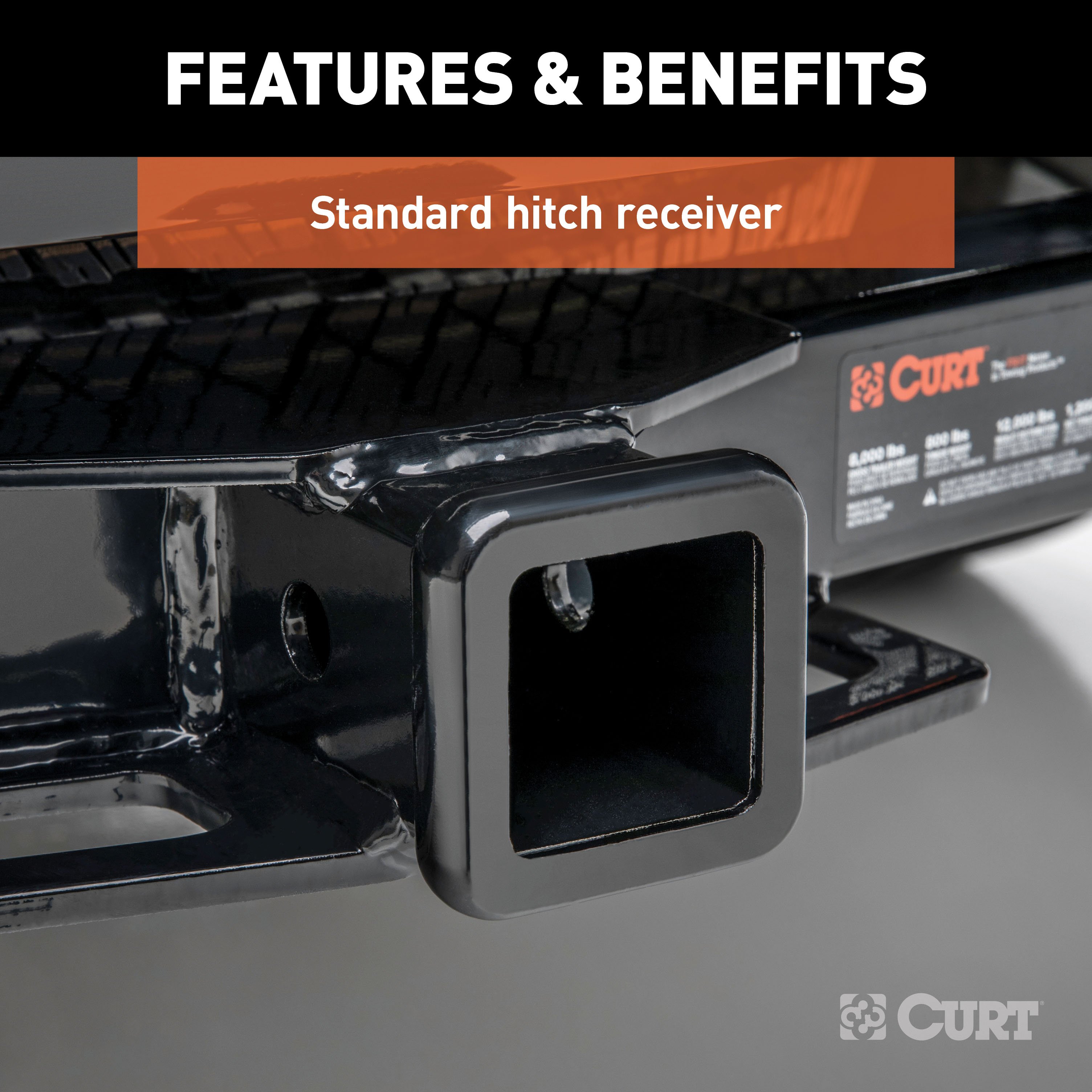
- Equipped with an open-back receiver for easy cleaning
- Limited lifetime warranty (one-year finish, one-year parts)
- Made in USA (may include imported hardware)
CURT 56148 Vehicle-Side Custom 4-Pin Trailer Wiring Harness
Manufactured by: Curt
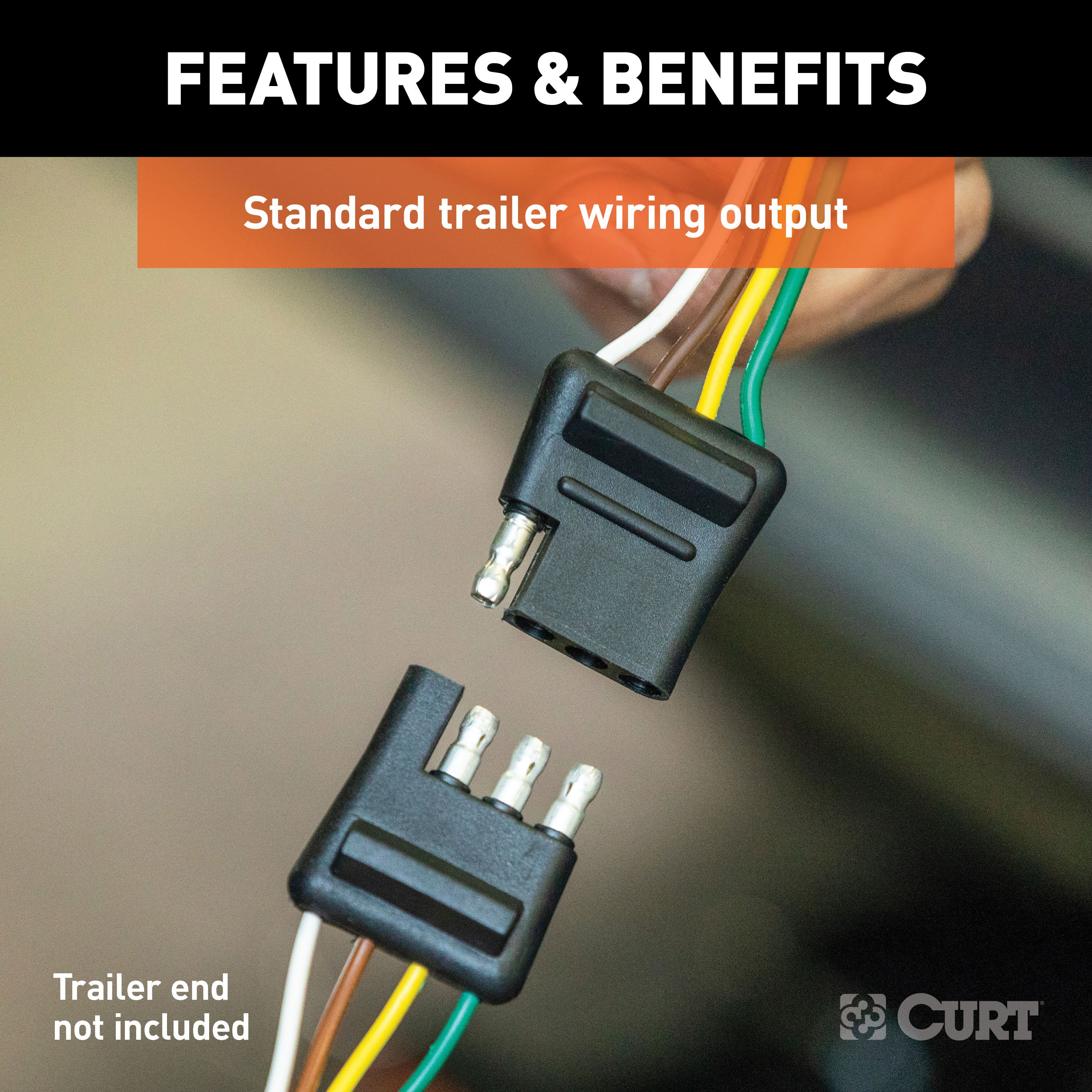
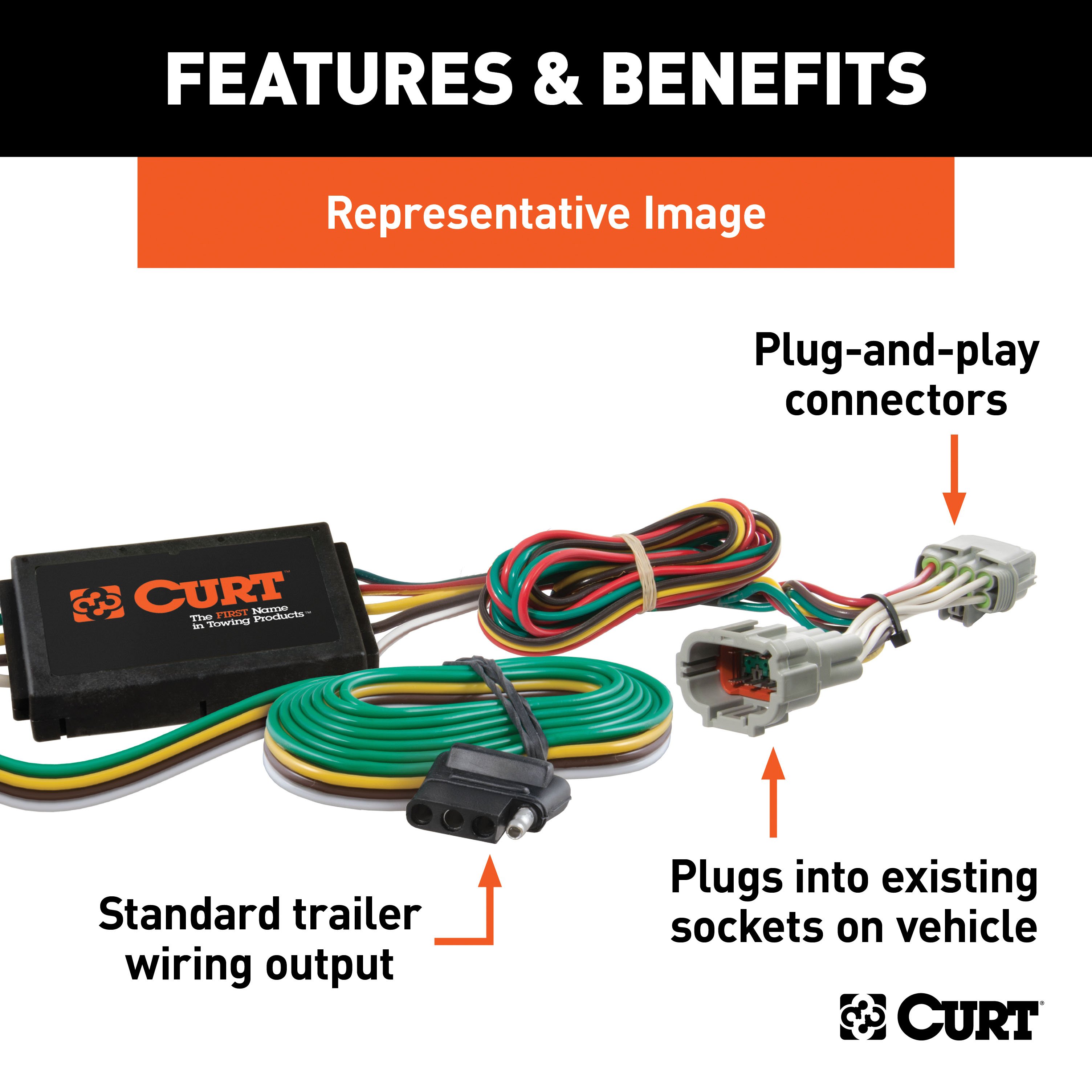
If your vehicle is not equipped with wiring for towing a trailer, CURT custom wiring is the ideal solution A custom wiring harness -- also called a T-connector -- is a simple, plug-and-play electrical device that plugs into your automotive electric system and provides a standard, universal trailer wiring connection This is done using two or more vehicle-specific, OEM-compatible connectors to plug into the taillight assembly, eliminating the need for cutting, splicing and soldering during installation.
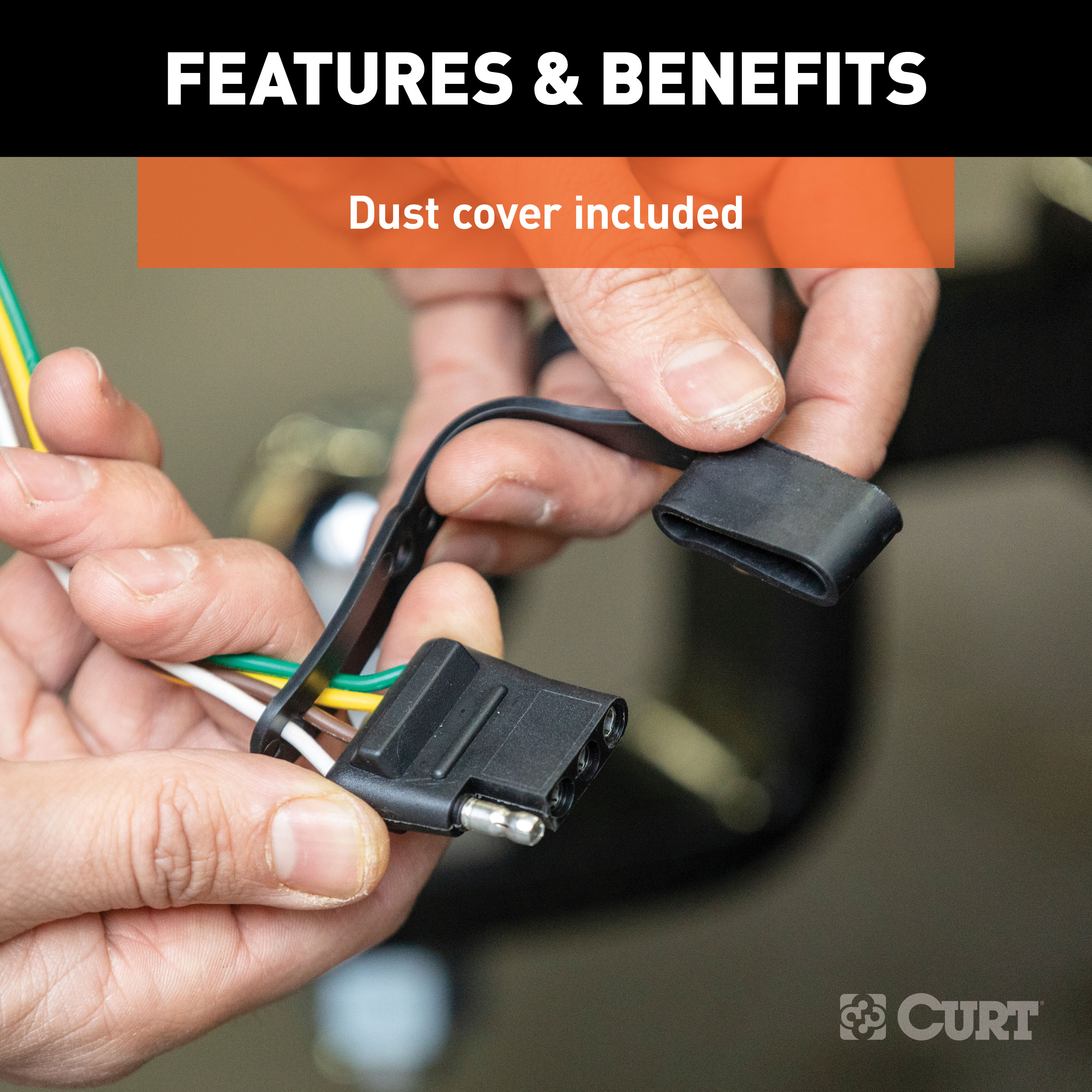
Custom wiring harnesses are made vehicle-specific, and while they are not available for all vehicles, they do offer one of the fastest, easiest and most secure ways to wire a vehicle for towing This particular plug-in harness provides a 4-way flat connector socket and is designed to be a custom wiring harness to fit certain years of the Nissan NV1500, NV2500 and NV3500 (to verify your vehicle compatibility, see application info) It comes with all necessary wiring components to establish a reliable trailer wiring connection, as well as a dust cover to keep the connector clean when not in use.
You have a picture in mind of your next destination -- maybe it's the boat landing at your favorite fishing spot, maybe it's a campsite that overlooks one of nature's masterpieces, or maybe it's the next big jobsite However, turning that picture into a reality takes more than just daydreaming It takes a solid connection and the right amount of power.
CURT custom wiring is made with some of the most sophisticated technology in the industry and is designed to install with ease, giving you a long-lasting electrical connection for your towing hitch setup..
Features:
- Plugs into vehicle tail light assembly to provide a 4-way flat socket
- Simple plug-and-play design eliminates the need for cutting or splicing
- 4-way flat output connects tail lights, brake lights and turn signals
- Equipped with tail light converter for vehicle-trailer compatibility
- Constructed with SMT circuitry for better performance and durability
- Dust cover included to keep connector clean when not in use
- Backed by a limited one-year warranty
Hitches Near Me: We operate out of several warehouses across the country, ensuring faster delivery to your location.
$299 99 $454.90 34% OFF
- Best Price on Web Guarantee
- Fastest Shipping
- FREE Shipping
- In Stock

We match lower prices from major authorized retailers for brand-new products in original packaging, provided the item is in stock. The competing seller must be an authorized, professional retail business; offers from
individuals, auctions, peer-to-peer sites, or unauthorized sellers don’t qualify. Used, refurbished, or open-box items are excluded.
Please see our full terms for details.
Verify Fitment
View products that fit your vehicle
Fits 's with the following styles:
View products that fit your vehicle
Fits 's with the following styles:
$454.90 $299 99
 Learn more
Questions? Call our Auto Experts at (877) 869-6690
Get it now, pay later
Select installments at checkout to split your purchase into 4 interest-free payments of $ every 2 weeks.
- No fees, ever.
- No impact on your credit score.
Payment options are offered by Affirm and are subject to an eligibility check and might not be available in all states. CA Residents: Loans by Affirm Loan Services, LLC are made or arranged pursuant to a California Finance Lender license.
Installments in partnership with


Each may be shipped from a separate location, and therefore, may arrive at different times
Product Details
- Brand: Curt
- Model: 13109 56148-CH3081
- Includes: Class 3 Trailer Tow Hitch, Custom Wiring Harness
Compatibility Chart
| Year Range | Make | Model | Style |
|---|
This Trailer Tow Hitch + 4-Flat Fits The Following Vehicles:
2012 - 2021 Nissan NV1500 All Models
This Trailer Tow Hitch + 4-Flat Includes the Following Parts:
- Class 3 Trailer Hitch, 2" Receiver (Easy Bolt-On, No Drilling)
- Custom Wiring Harness, 4-Way Flat Output (Plug & Play)
- Installation instructions, schematics, diagrams, and hardware (if required).
List of Fitment Years:
2012, 2013, 2014, 2015, 2016, 2017, 2018, 2019, 2020, 2021
CURT 13109 Class 3 Trailer Hitch, 2-Inch Receiver
Manufactured by: Curt
Whatever your task at hand -- whether it's launching that boat before daybreak, setting up your camper before the rush or getting a final load to the dump before close -- CURT class 3 trailer hitches offer the strength needed for serious towing They make it easy to hitch up and Bring It, offering a vehicle-specific fit and the weight capacity to handle a variety of trailers Custom class 3 hitches are the most common type of receiver hitch for pickup trucks and SUVs.
Because of their weight range, they are also found on full-size cars, crossovers and minivans Each custom-fit class 3 hitch package is made for vehicle-specific mounting This particular kit fits certain years of the Nissan NV1500, NV2500 and NV3500 (see application info to verify vehicle compatibility).
It provides a weight carrying capacity of 7,500 lbs GTW and 750 lbs TW.
It is also compatible with a weight distribution hitch for level towing and a rating of 10,000 lbs WD and 1,000 lbs WDTW.
CURT class 3 trailer hitches are typically used to attach and haul utility trailers, boat trailers, campers, snowmobile or ATV haulers and more (NOTE: Never exceed the lowest-rated towing component) Each class 3 hitch has a 2" receiver tube and is tested in accordance with SAE J684 for safety To ensure that CURT class 3 receiver hitches have what it takes for serious trailering, they are designed using a hands-on approach and are constructed with rugged, high-strength steel and precise welding.
We also protect our class 3 hitches in a co-cured finish of liquid A-coat and black powder coat for superior resistance to rust, chipping and UV damage..
Features:
- Rated to 7,500 lbs. gross trailer weight and 750 lbs. tongue weight
- Compatible with weight distribution hitch (10,000 lbs. WD / 1,000 lbs. WDTW)
- Engineered with a vehicle-specific design for a custom fit
- Tested for safety in accordance with SAE J684
- Precisely welded for superior strength and fit
- Protected by a durable high-gloss black powder coat finish
- Co-cured in a rust-resistant liquid A-coat, inside and out
- Equipped with an open-back receiver for easy cleaning
- Limited lifetime warranty (one-year finish, one-year parts)
- Made in USA (may include imported hardware)
CURT 56148 Vehicle-Side Custom 4-Pin Trailer Wiring Harness
Manufactured by: Curt
If your vehicle is not equipped with wiring for towing a trailer, CURT custom wiring is the ideal solution A custom wiring harness -- also called a T-connector -- is a simple, plug-and-play electrical device that plugs into your automotive electric system and provides a standard, universal trailer wiring connection This is done using two or more vehicle-specific, OEM-compatible connectors to plug into the taillight assembly, eliminating the need for cutting, splicing and soldering during installation.
Custom wiring harnesses are made vehicle-specific, and while they are not available for all vehicles, they do offer one of the fastest, easiest and most secure ways to wire a vehicle for towing This particular plug-in harness provides a 4-way flat connector socket and is designed to be a custom wiring harness to fit certain years of the Nissan NV1500, NV2500 and NV3500 (to verify your vehicle compatibility, see application info) It comes with all necessary wiring components to establish a reliable trailer wiring connection, as well as a dust cover to keep the connector clean when not in use.
You have a picture in mind of your next destination -- maybe it's the boat landing at your favorite fishing spot, maybe it's a campsite that overlooks one of nature's masterpieces, or maybe it's the next big jobsite However, turning that picture into a reality takes more than just daydreaming It takes a solid connection and the right amount of power.
CURT custom wiring is made with some of the most sophisticated technology in the industry and is designed to install with ease, giving you a long-lasting electrical connection for your towing hitch setup..
Features:
- Plugs into vehicle tail light assembly to provide a 4-way flat socket
- Simple plug-and-play design eliminates the need for cutting or splicing
- 4-way flat output connects tail lights, brake lights and turn signals
- Equipped with tail light converter for vehicle-trailer compatibility
- Constructed with SMT circuitry for better performance and durability
- Dust cover included to keep connector clean when not in use
- Backed by a limited one-year warranty
Hitches Near Me: We operate out of several warehouses across the country, ensuring faster delivery to your location.
| Default | |
| Brand | Curt |
| Gross Towing Weight | 7,500 LB |
| Trailer Hitch Receiver Size | 2 Inch |
| Trailer Wiring Output Type | 4-Flat |
| Hitch Class | 3 |
| Trailer Wiring Install Style | Plug&Play |
| Drilling Required | No |
| Tongue Weight Capacity | 750 LB |
| Gross Towing Weight w/ Weight Distribution Kit | 10,000 LB |
| Maximum Tongue Weight w/ Weight Distribution Kit | 1,000 LB |
| Hitch Visibility | Exposed |
| Cross-Tube Type | Square Tube |
Ask a Question about For 2012-2021 Nissan NV1500 Trailer Hitch + Wiring 4 Pin Fits All Models Curt 13109 56148 2 inch Tow Receiver
Be the first to ask a question.


