Product Details
- Brand: Curt
- Model: 13411 59236-CH2915
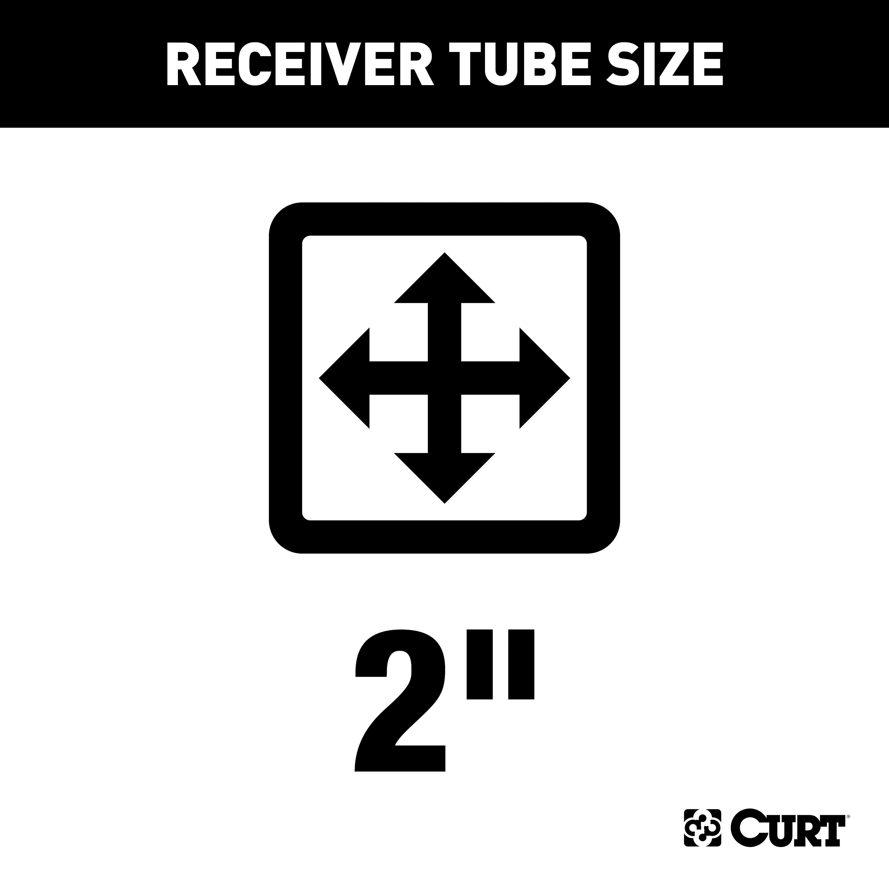
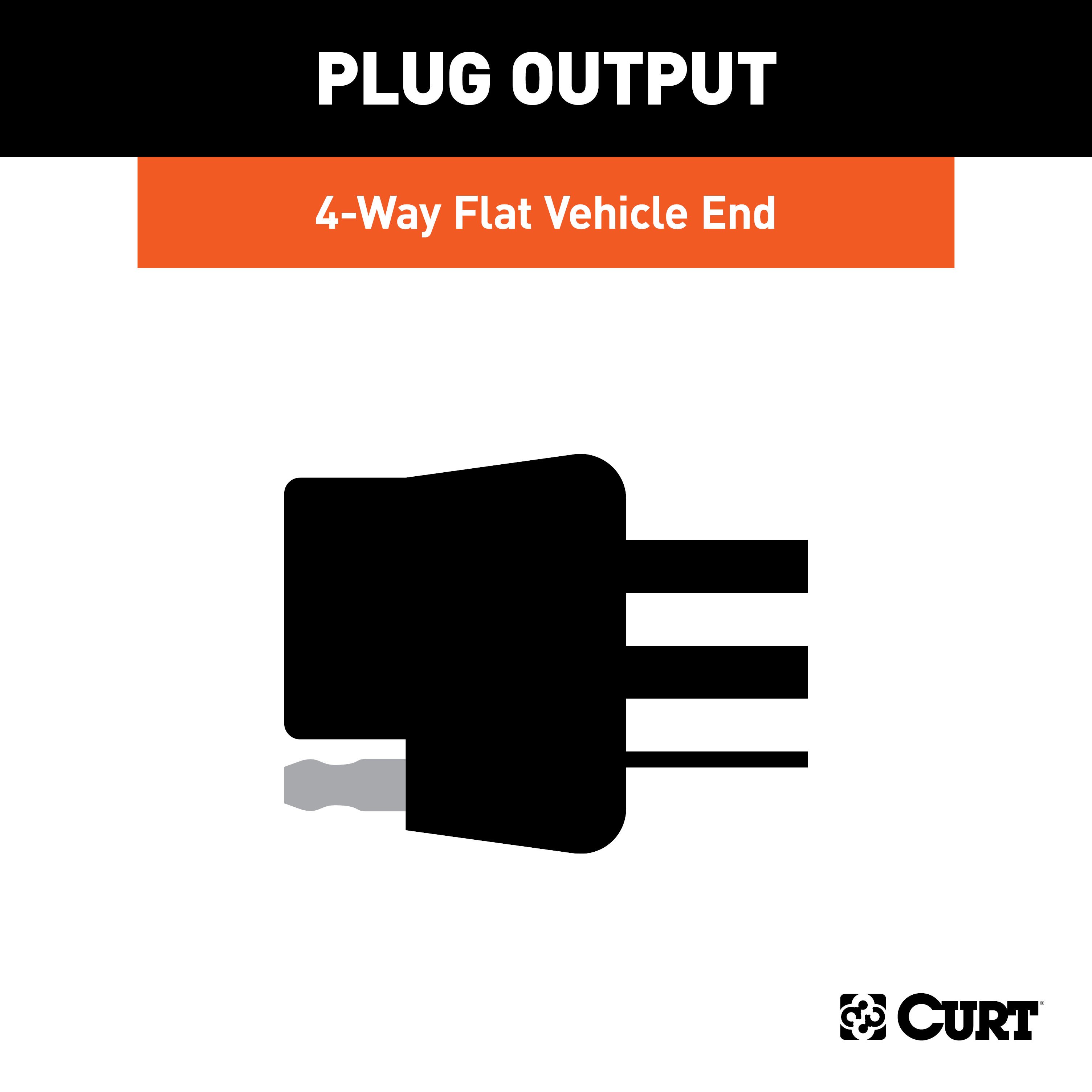
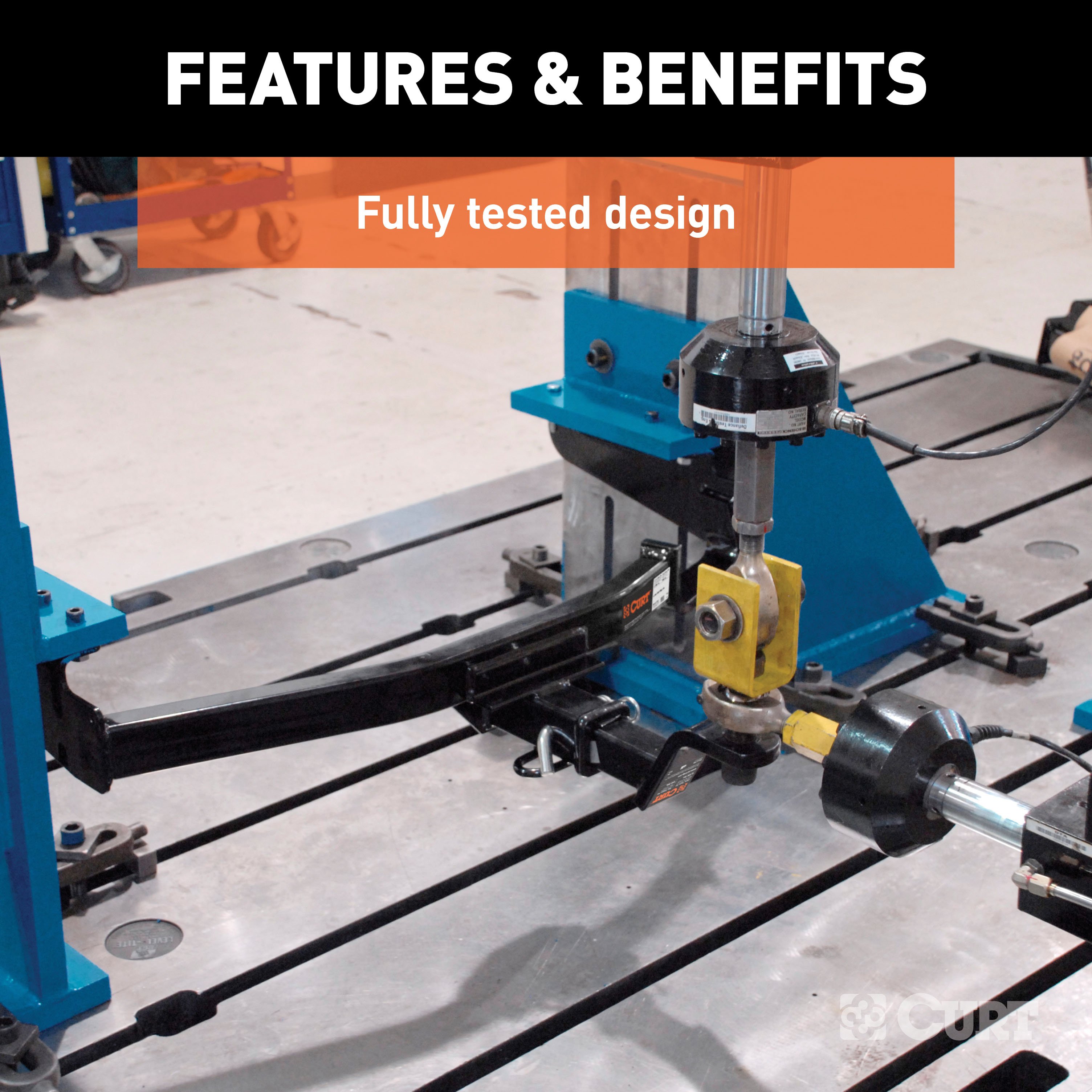
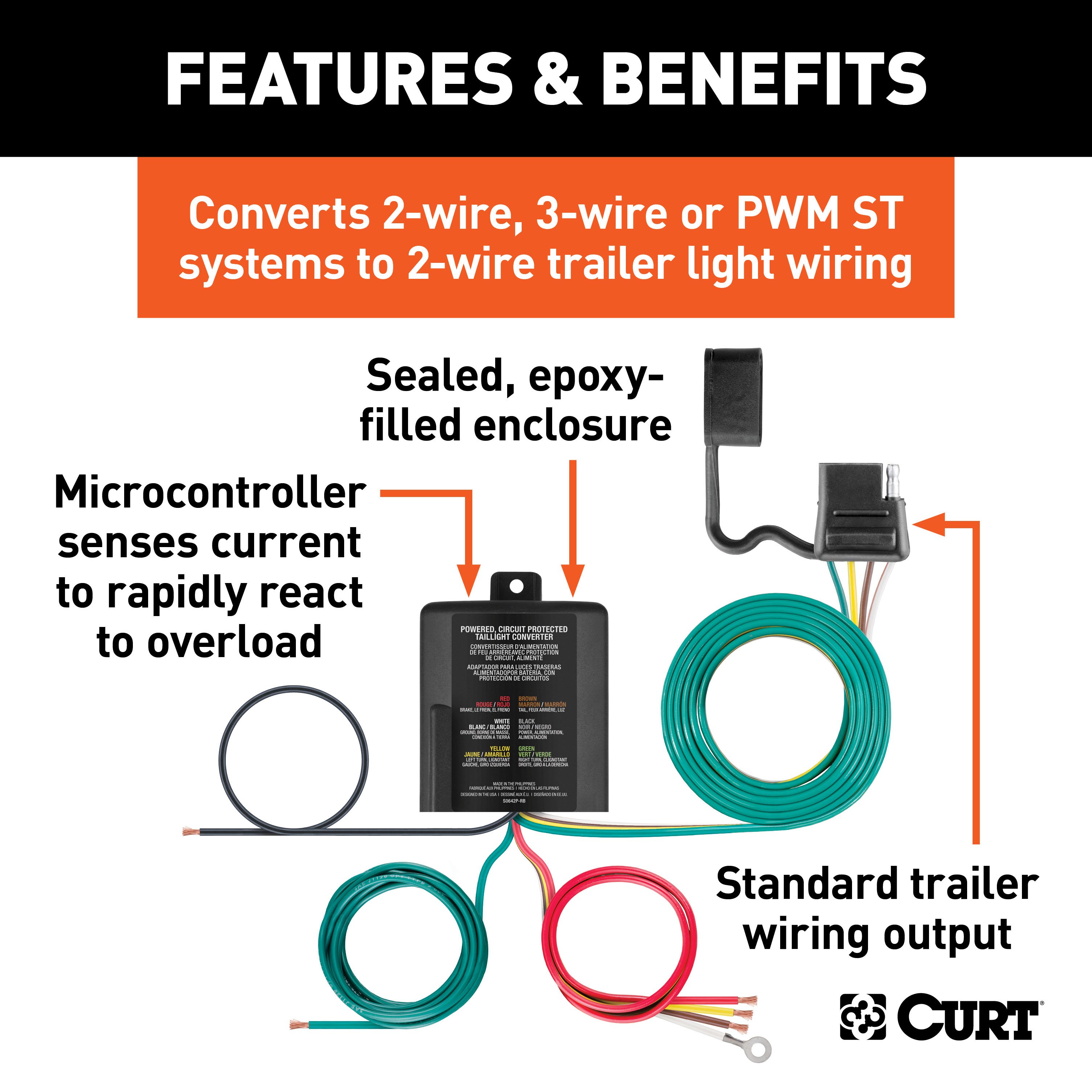
- Includes: Class 3 Trailer Tow Hitch, Multi-Function Taillight Converter Kit
Compatibility Chart
Description
Get Expert Help
For 2012-2015 Mercedes ML350 Trailer Hitch + Wiring 4 Pin Except Diesel Curt 13411 59236 2 inch Tow Receiver Install Notes
Installation Instructions for 2012-2018 Mercedes-Benz ML350, GLE350, and GLE43 AMG
Part Numbers:
- 13411
Tools Required:
- Ratchet
- Torque Wrench
- 10mm, 13mm, 16mm, 3/4" Sockets
- 6" Socket Extension
- E10 Torx Bit
- Aviation Shears
- 3/4" Boxed End Wrench
- Marker
- Safety Glasses
Step-by-Step Instructions:
Step 1: Remove lower bumper fascia and brackets
- Use a 10mm socket to remove (4) screws securing the lower bumper fascia to (3) brackets on the rear bulkhead.
- Remove the (3) brackets using a 10mm socket:
- Outer brackets have (2) metal nuts.
- Inner bracket has (1) plastic nut.
- Return the brackets to the vehicle owner.
Step 2: Remove exhaust heat shield fasteners
- Remove (2) external Torx screws from the exhaust heat shield using an E10 Torx bit.
- Trim and bend the heat shield as needed for clearance, referencing the provided trim diagram.
Step 3: Remove bumper beam nuts
- Use a 13mm socket to remove (4) M10 nuts from the lower bumper beam studs.
- Trim caulking around the bumper beam studs as needed.
Step 4: Position the main weldment
- Raise the main weldment (13411-MBWA) into position over the bumper beam studs.
- Loosely reinstall the (4) M10 nuts and (2) M8 screws removed in Steps 2 and 3.
Step 5: Install tail bracket assembly
- Place the Tail Bracket Clamp Plate (13411-TBC) between the rear differential and the cross member.
- Position the Tail Bracket Weldment (13411-TBWA) between the Main Body Weldment and the vehicle cross member.
- Loosely install the 1/2" fasteners as shown in the diagram.
Step 6: Torque all fasteners
- Torque fasteners in the following order:
- M8 fasteners to 25 lb-ft
- M10 fasteners to 38 lb-ft
- 1/2" fasteners to 110 lb-ft
Step 7: Install clip nuts and lower fascia
- Remove clip nuts from the (3) bumper brackets removed in Step 1 and install them onto the tabs on the Main Body Weldment.
- Align the clips with the lower bumper fascia tabs and reinstall the (4) screws removed in Step 1.
Hardware List:
- (1) Weldment Assembly (13411-MBWA)
- (1) Tail Bracket Clamp Plate (13411-TBC)
- (1) Tail Bracket Weldment Assembly (13411-TBWA)
- (2) 1/2"-13 UNC x 3" Grade 8 Carriage Bolts
- (2) 1/2"-13 UNC x 1-1/4" Grade 8 Carriage Bolts
- (4) 1/2"-13 UNC Grade 8 Serrated Flange Nuts
Safety Notes:
- Always wear safety glasses during installation.
- Periodically inspect the hitch to ensure all fasteners are tight and structural components are secure.
- Stabilizing straps (#18050) are required for all non-trailer (wheel-less) loads.
- Never exceed the vehicle manufacturer's recommended towing capacity.
Specifications:
- Gross Trailer Weight: 7,000 lbs
- Tongue Weight: 700 lbs
For additional support, contact Technical Support at 877-287-8634.
Installation Instructions for 2012-2018 Mercedes-Benz ML350, GLE350, and GLE43 AMG
Part Numbers:
- 13411
Tools Required:
- Ratchet
- Torque Wrench
- 10mm, 13mm, 16mm, 3/4" Sockets
- 6" Socket Extension
- E10 Torx Bit
- Aviation Shears
- 3/4" Boxed End Wrench
- Marker
- Safety Glasses
Step-by-Step Instructions:
Step 1: Remove Lower Bumper Fascia and Brackets
- Use a 10mm socket to remove (4) screws securing the lower bumper fascia to (3) brackets on the rear bulkhead.
- Remove the (3) brackets using a 10mm socket:
- Outer brackets have (2) metal nuts.
- Inner bracket has (1) plastic nut.
- Return the brackets to the vehicle owner.
Step 2: Remove Exhaust Heat Shield Fasteners
- Remove (2) external Torx screws from the exhaust heat shield using an E10 Torx bit.
- Trim and bend the heat shield as needed for clearance, referencing the provided trim diagram.
Step 3: Remove Bumper Beam Nuts
- Use a 13mm socket to remove (4) M10 nuts from the lower bumper beam studs.
- Trim caulking around the bumper beam studs as needed.
Step 4: Position the Main Weldment
- Raise the main weldment (13411-MBWA) into position over the bumper beam studs.
- Loosely reinstall the (4) M10 nuts and (2) M8 screws removed in Steps 2 and 3.
Step 5: Install Tail Bracket Assembly
- Place the Tail Bracket Clamp Plate (13411-TBC) between the rear differential and the cross member.
- Position the Tail Bracket Weldment (13411-TBWA) between the Main Body Weldment and the vehicle cross member.
- Loosely install the 1/2" fasteners as shown in the diagram.
Step 6: Torque All Fasteners
- Torque fasteners in the following order:
- M8 fasteners to 25 lb-ft
- M10 fasteners to 38 lb-ft
- 1/2" fasteners to 110 lb-ft
Step 7: Install Clip Nuts and Lower Fascia
- Remove clip nuts from the (3) bumper brackets removed in Step 1 and install them onto the tabs on the Main Body Weldment.
- Align the clips with the lower bumper fascia tabs and reinstall the (4) screws removed in Step 1.
Hardware List:
- (1) Weldment Assembly (13411-MBWA)
- (1) Tail Bracket Clamp Plate (13411-TBC)
- (1) Tail Bracket Weldment Assembly (13411-TBWA)
- (2) 1/2"-13 UNC x 3" Grade 8 Carriage Bolts
- (2) 1/2"-13 UNC x 1-1/4" Grade 8 Carriage Bolts
- (4) 1/2"-13 UNC Grade 8 Serrated Flange Nuts
Safety Notes:
- Always wear safety glasses during installation.
- Periodically inspect the hitch to ensure all fasteners are tight and structural components are secure.
- Stabilizing straps (#18050) are required for all non-trailer (wheel-less) loads.
- Never exceed the vehicle manufacturer's recommended towing capacity.
Specifications:
- Gross Trailer Weight: 7,000 lbs
- Tongue Weight: 700 lbs
Attention: This is a summary of the installation procedure. For complete installation instructions, including diagrams and detailed information from the manufacturer, please download the full installation PDF.
Need Assistance? For technical support and assistance, our team of experts is available to help. You can reach our tech support by visiting www.trailerjacks.com or calling 877-869-6690.
Warranty Information:
The product is covered under warranty for the duration specified. For complete warranty instructions, please download the full installation PDF.
End of Instructions
Installation Instructions for Wiring Harness with Powered Converter
Part Numbers:
- 59236
Wiring Access Location:
Refer to the wiring location guides based on vehicle type provided in the manual:
SUVs and Vans:
- S1: Behind driver-side taillight housing
- S2: Behind passenger-side taillight housing
- S3: Behind driver-side rear access panel
- S4: Behind passenger-side rear access panel
- S5: Behind driver-side rear bumper
- S6: Behind the center of the rear bumper
- S7: Behind passenger-side rear bumper
- S8: Under rear floor panel
Passenger Cars:
- P1: Behind driver-side taillight housing, outside of the trunk
- P2: Behind passenger-side taillight housing, outside of the trunk
- P3: Behind driver-side taillight housing, inside the trunk
- P4: Behind passenger-side taillight housing, inside the trunk
- P5: Behind driver-side rear bumper
- P6: Behind the center of the rear bumper
- P7: Behind passenger-side rear bumper
Trucks:
- T1: Behind driver-side taillight housing
- T2: Behind passenger-side taillight housing
- T3: Behind driver-side rear bumper
- T4: Behind the center of the rear bumper fascia
- T5: Behind passenger-side rear bumper
Determining Vehicle Wiring Types:
To identify the vehicle wiring type, follow these steps:
- Ensure all lights on the vehicle are off.
- Probe the taillight connectors while they remain connected to the vehicle.
- Use the following wiring descriptions to determine the vehicle type:
Wiring Types:
-
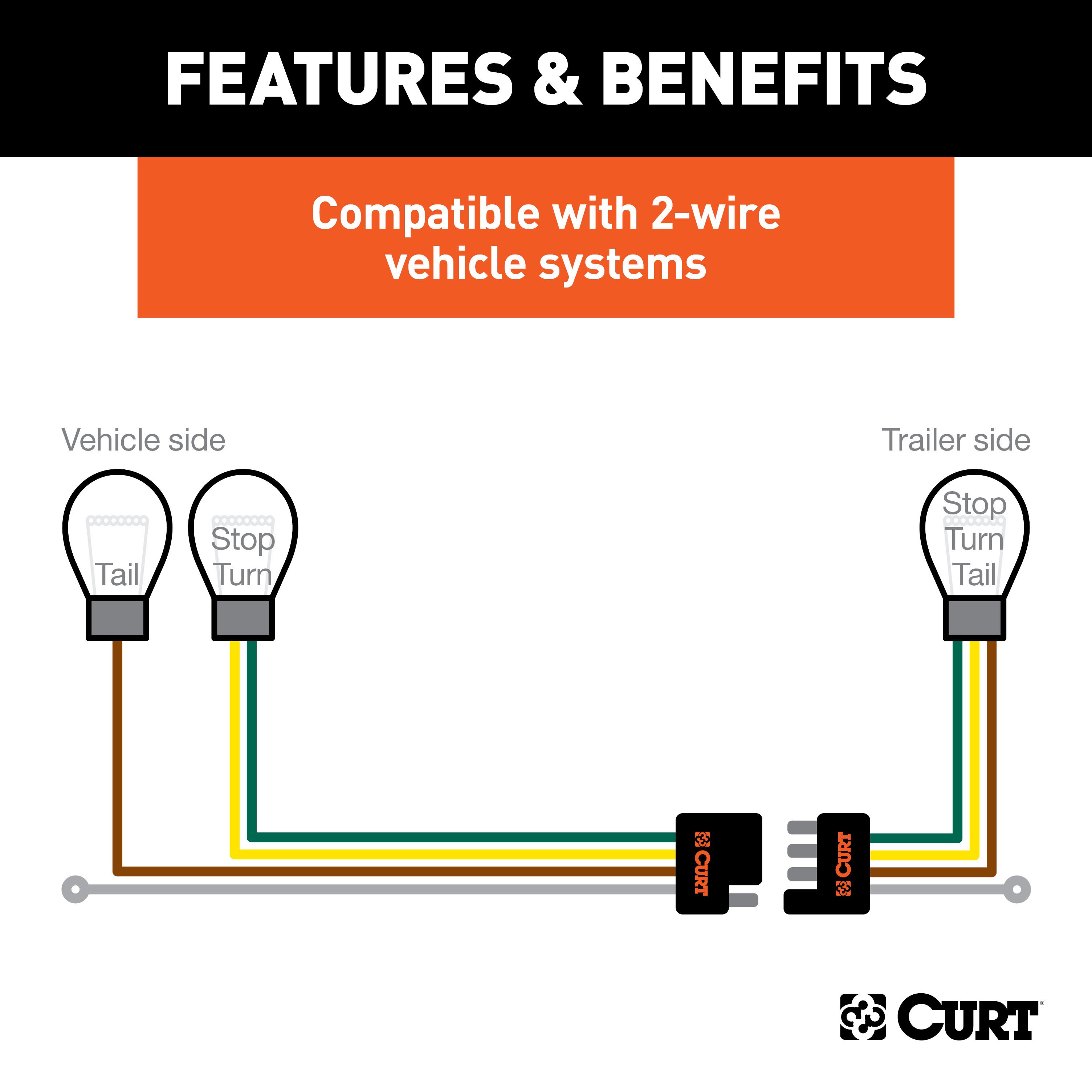
Two-Wire System:
- Combined stop and turn signal with an independent tail signal.
- Indicator: Flashing signal on one side for turn signals; both sides activate for brakes.
-
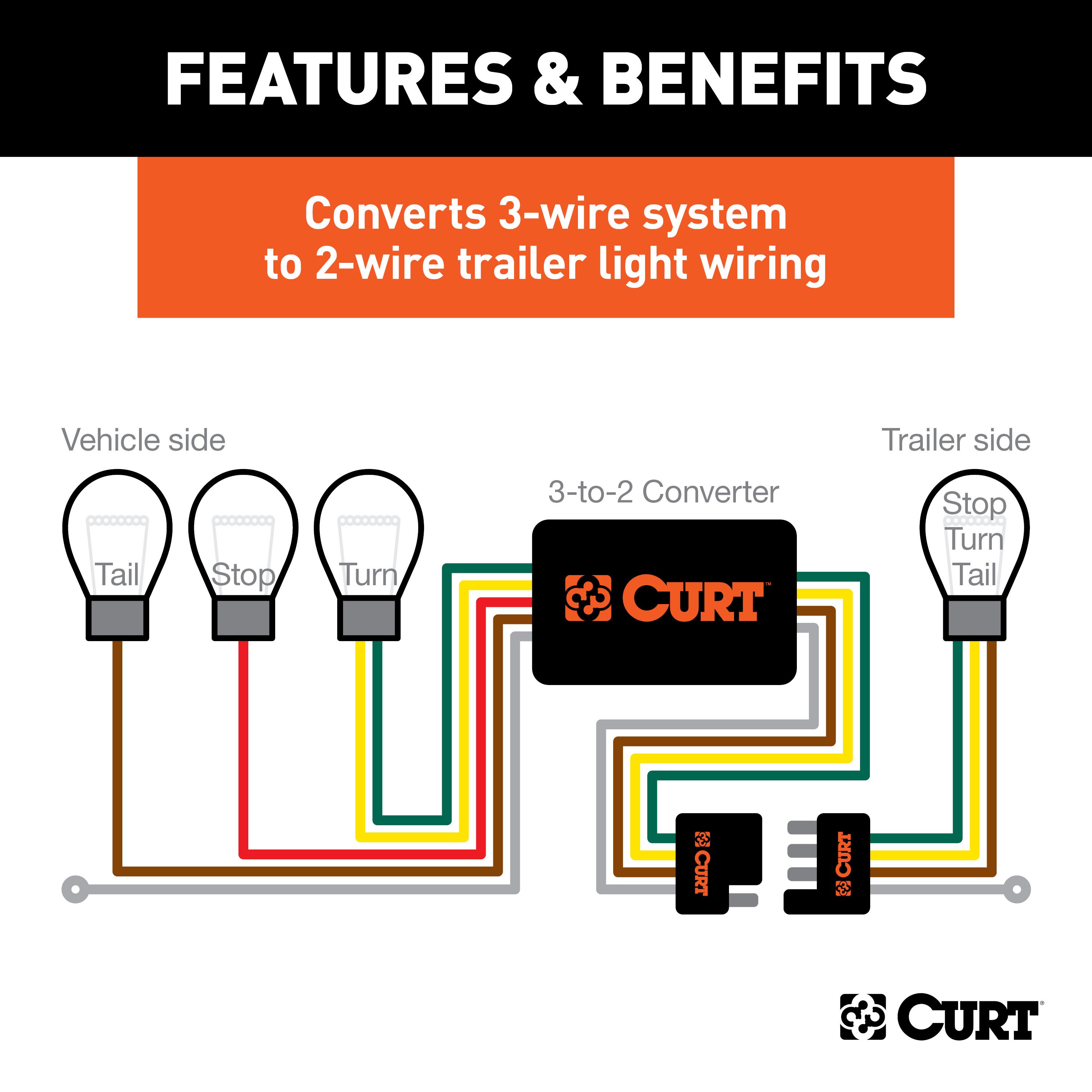
Three-Wire System:
- Independent stop, turn, and tail signals.
- Indicator: Separate wires for turn signals and brake lights.
-
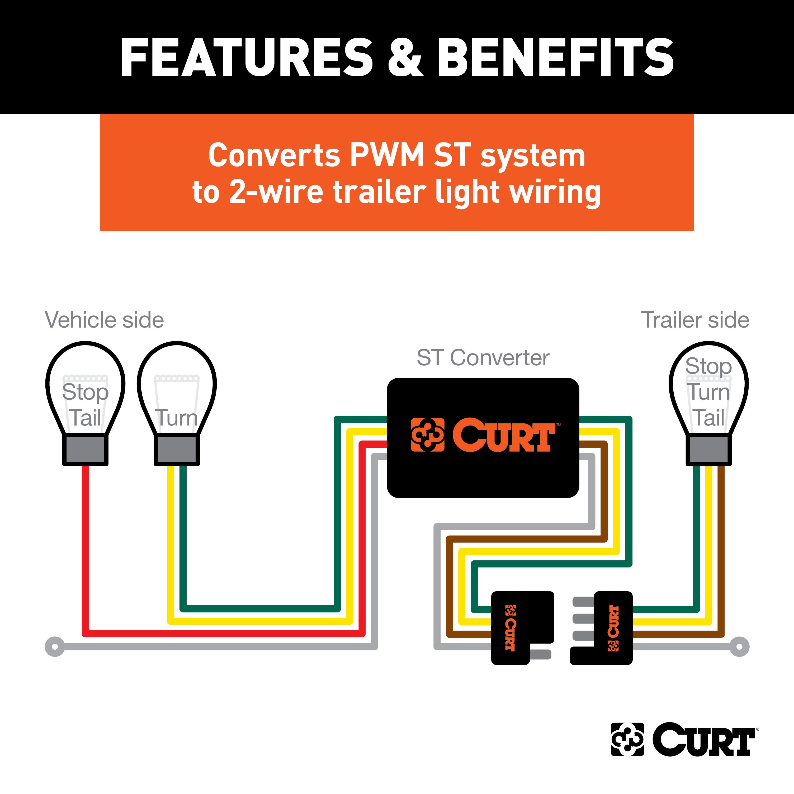
PWM-ST System:
- Combined stop and tail signal with an independent turn signal.
- Indicator: Stop and tail signals use the same wire; separate turn signal wires.
-
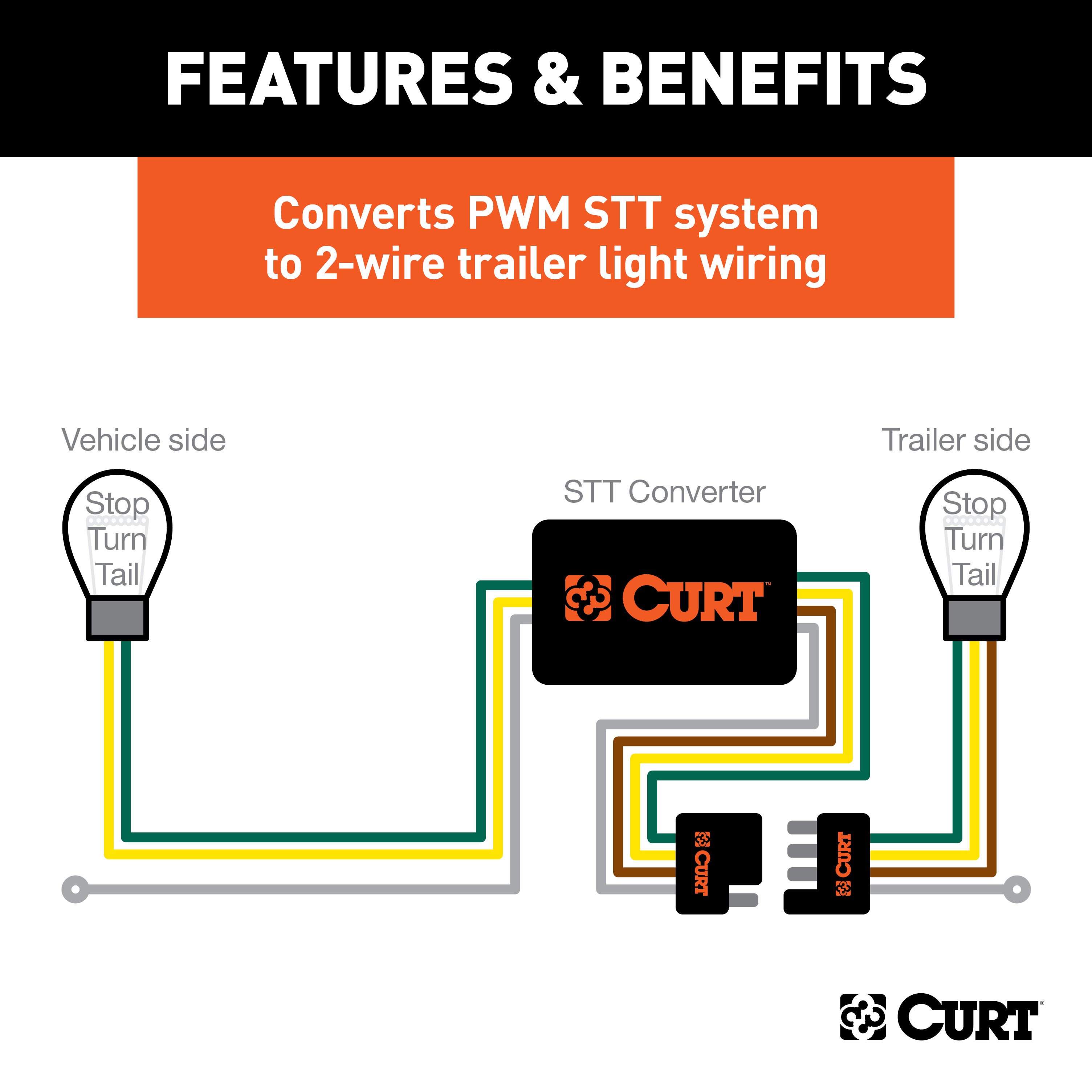
PWM-STT System:
- Combined stop, turn, and tail signal.
- Indicator: A single wire serves stop, turn, and tail functions.
Tools Required:
- Test light
- Utility knife
- Electrical tape
- Wire crimper
- Paper
- Wire stripper
- Pen
Step-by-Step Instructions:
-
Locate the Vehicle Battery
- Disconnect the negative battery terminal securely.
-
Identify Vehicle Taillight Wiring
- Use the wiring location guide and instructions for determining the wiring type.
-
Attach the Input Wires
- Match wires using snap locks:
- Green Wire: Splice to the right stop/turn wire.
- Red Wire: Ground with the white wire.
- Yellow Wire: Splice to the left stop/turn wire.
- Brown Wire: Splice to the tail wire.
- Match wires using snap locks:
-
Mount the Converter
- Secure the black converter box near the taillight using the provided double-sided tape.
-
Ground the White Wire
- Use the ring terminal and provided screw to ground the wire at a clean, rust-free location.
-
Route the Power Wire
- Route the black wire to the positive battery terminal, avoiding pinch points or hot components.
-
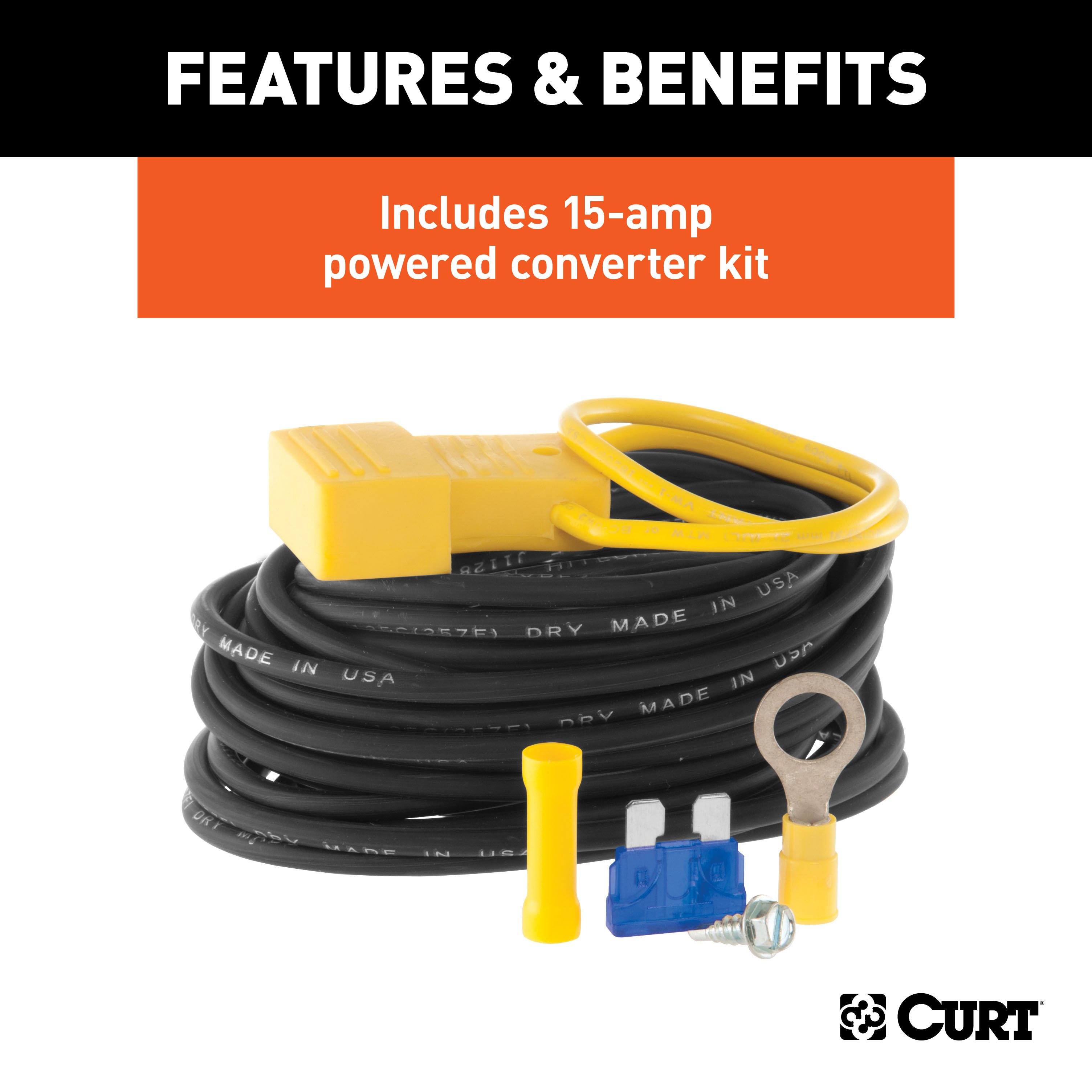
Install the Fuse
- Add the 15-amp fuse after completing all other steps.
-
Test the System
- Verify turn signals, brake lights, and tail lights using a test light or trailer.
-
Reinstall Components
- Reinstall all removed parts and reconnect the negative battery terminal.
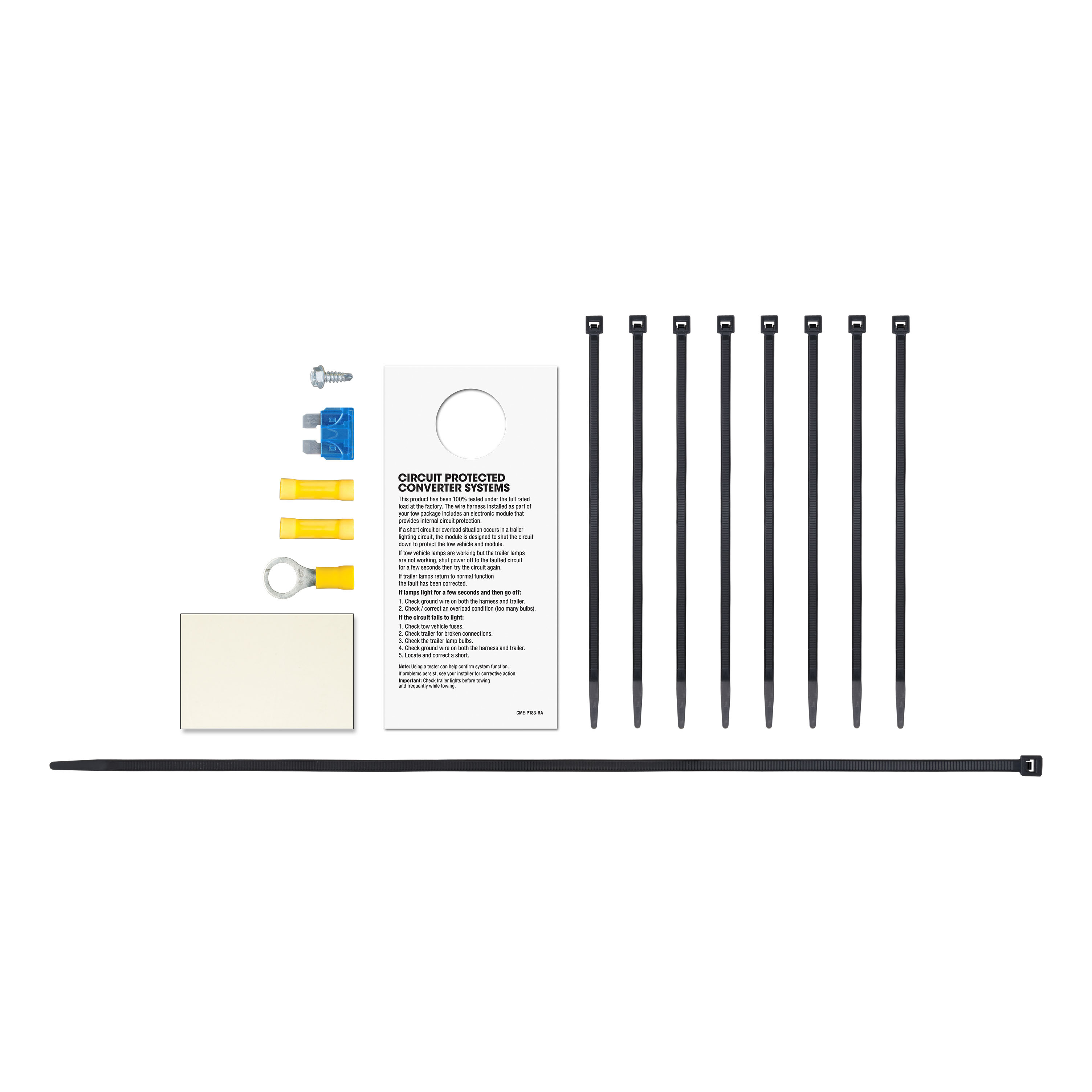
Hardware List:
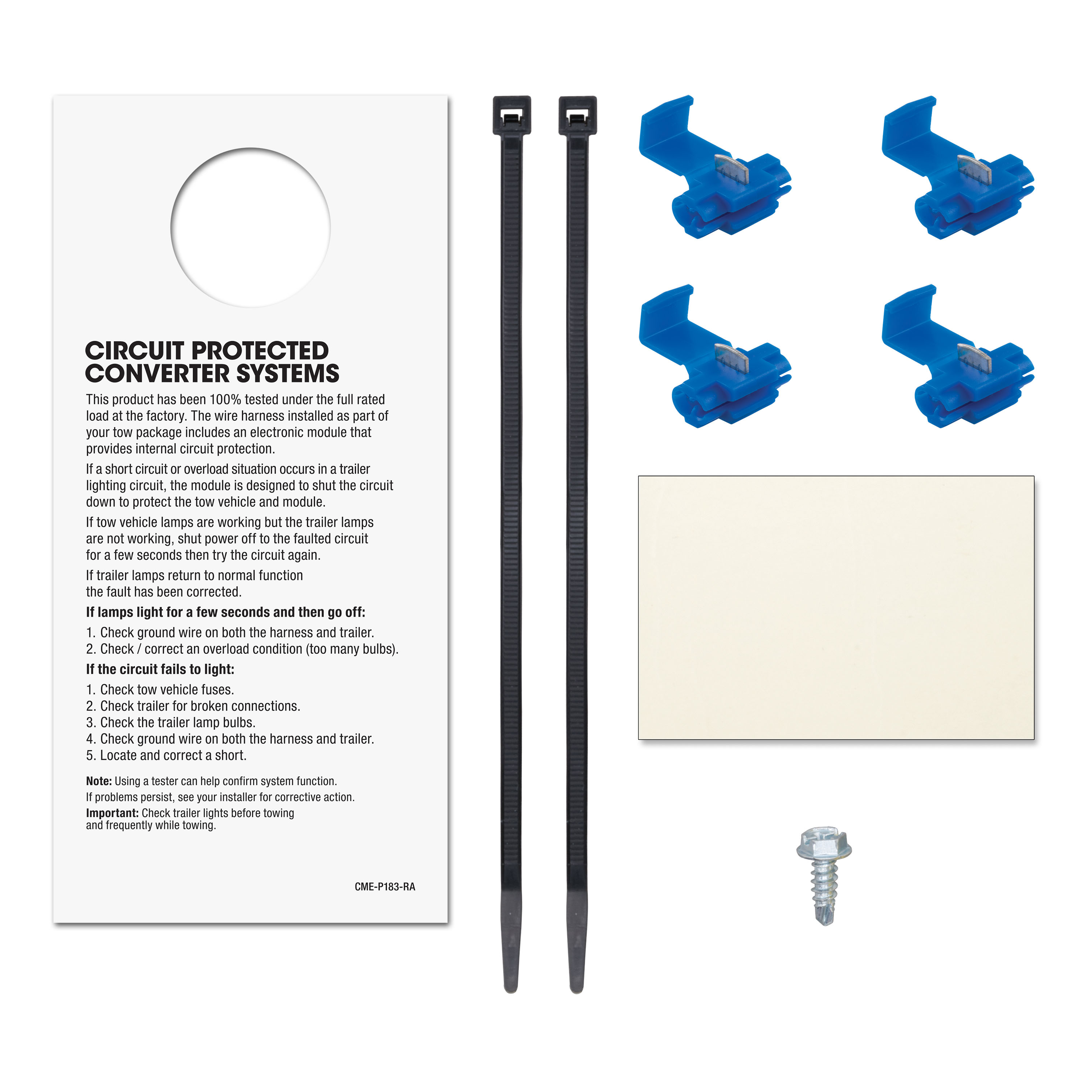
- Snap locks
- 15-amp fuse and holder
- Ring terminal
- Cable ties
- Double-sided tape
Safety Notes:
- Do not exceed product or tow vehicle lamp load ratings.
- Inspect all wiring periodically for damage or loose connections.
- Avoid drilling without confirming there are no hidden items behind the surface.
Specifications:
- Signal Circuits: 5.0-amps per side
- Tail/Running Circuits: 7.5-amps total
- Compliance: SAE J684
Additional Information:
- Attention: This is a summary of the installation procedure. For complete installation instructions, including diagrams and detailed information from the manufacturer, please download the full installation PDF.
Technical Support:
- For technical support and assistance, our team of experts is available to help. You can reach our tech support by visiting www.trailerjacks.com or calling 877-869-6690.
Warranty:
- Warranty Duration: [Insert warranty period]
- Coverage Details: [Insert coverage details]
- For complete warranty information, please download the full installation PDF.
Note: Ensure all connections are secure and test the wiring with a properly wired trailer or test light to confirm functionality.


