Product Details
- Brand: Curt
- Model: 13379 56093 57187 58303-CH1828
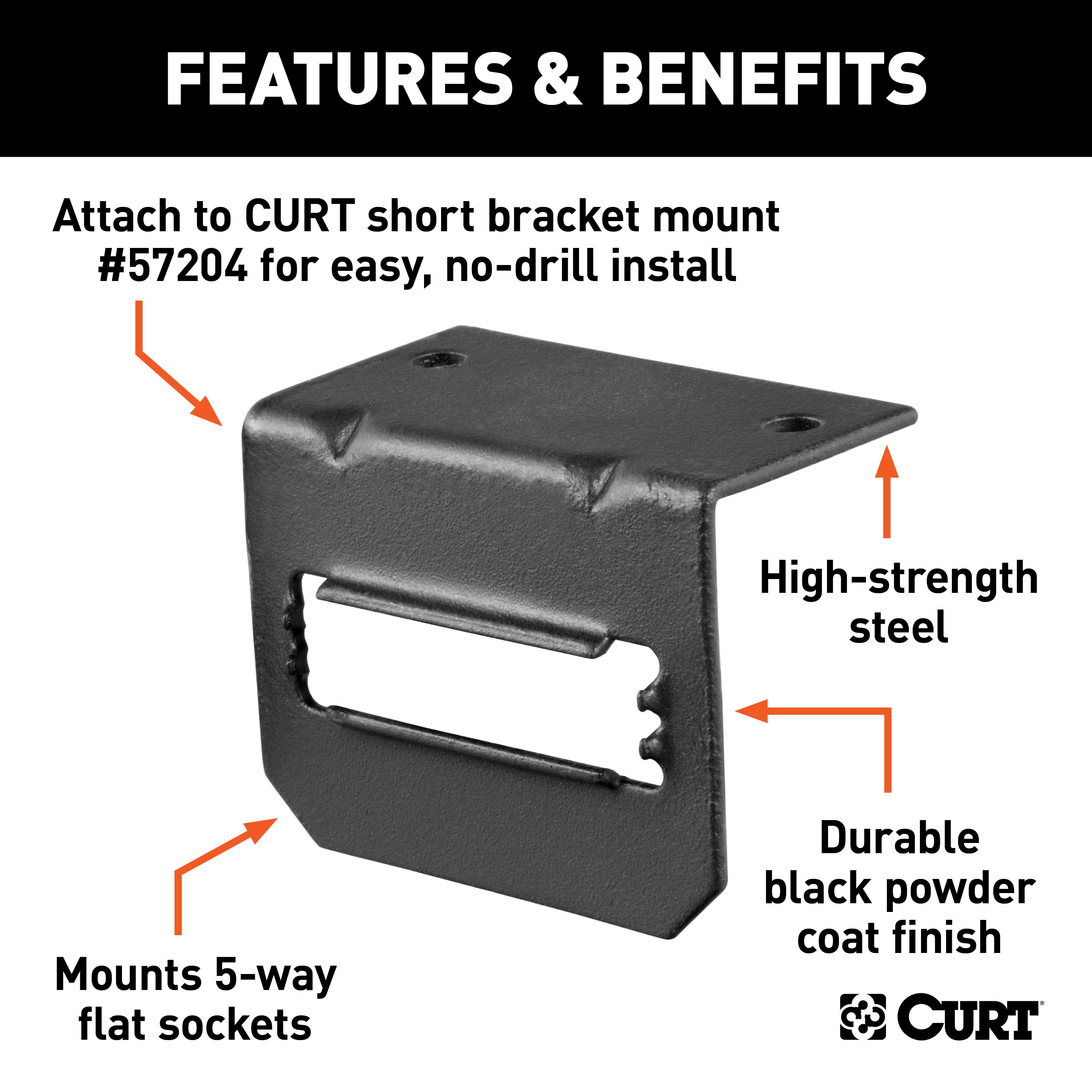
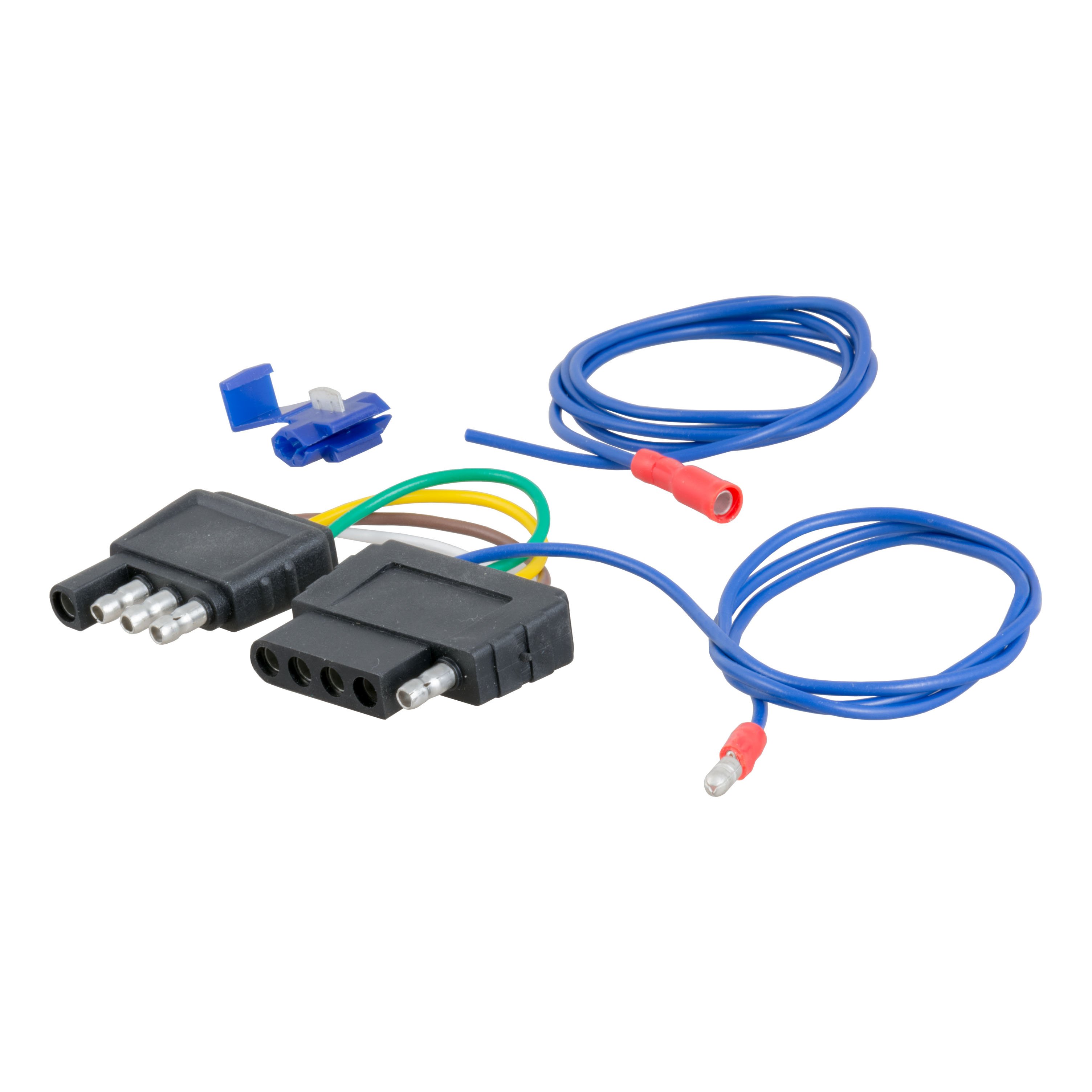
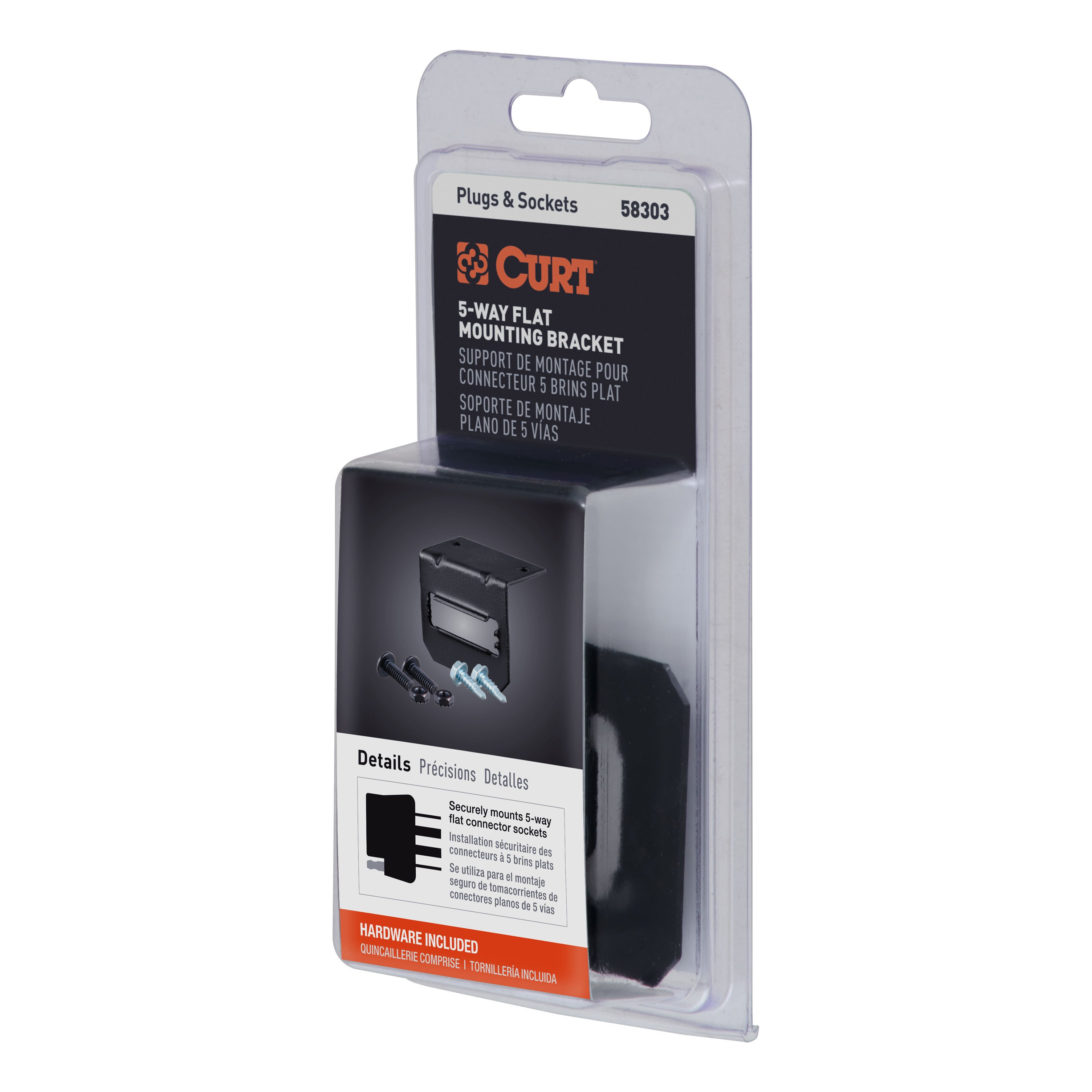
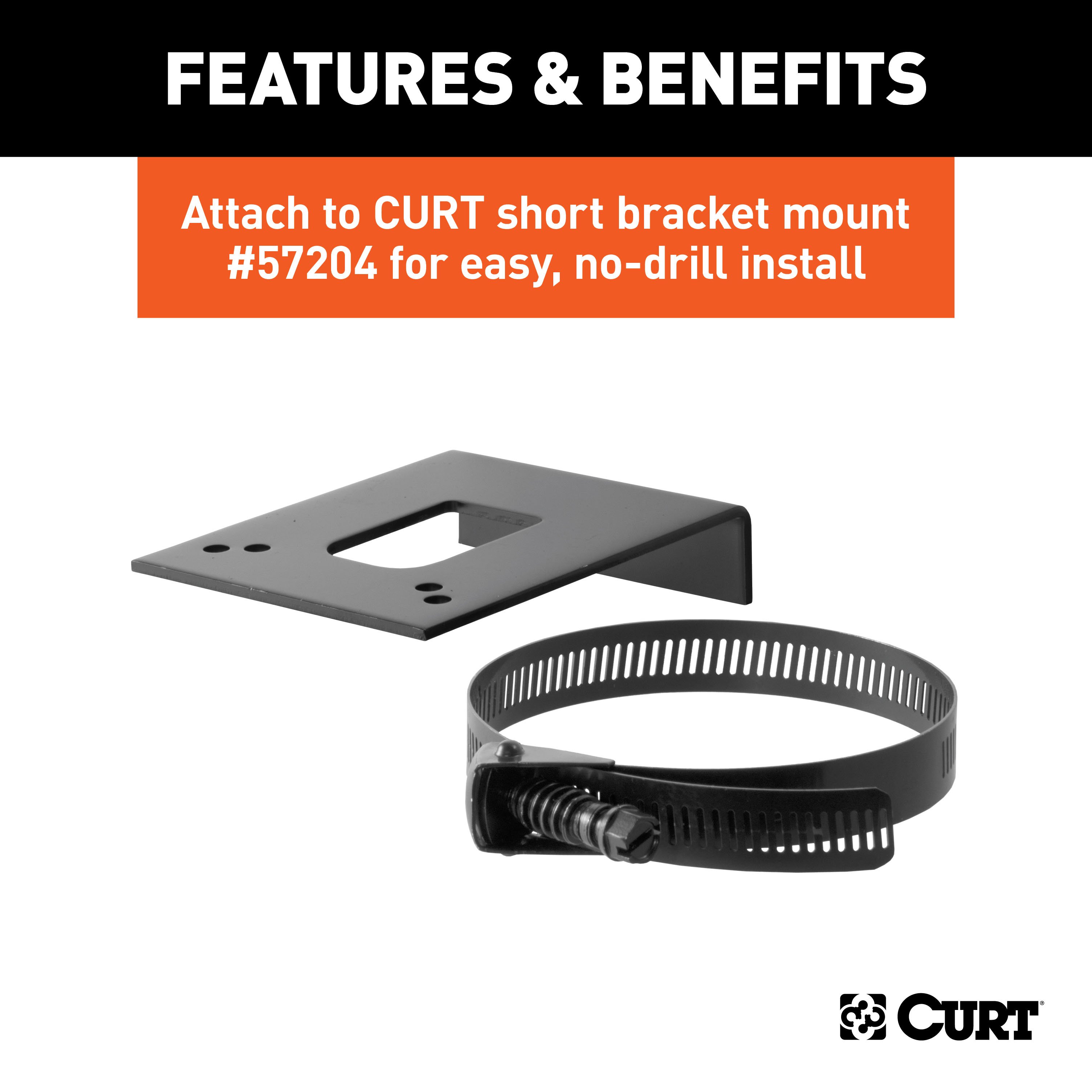
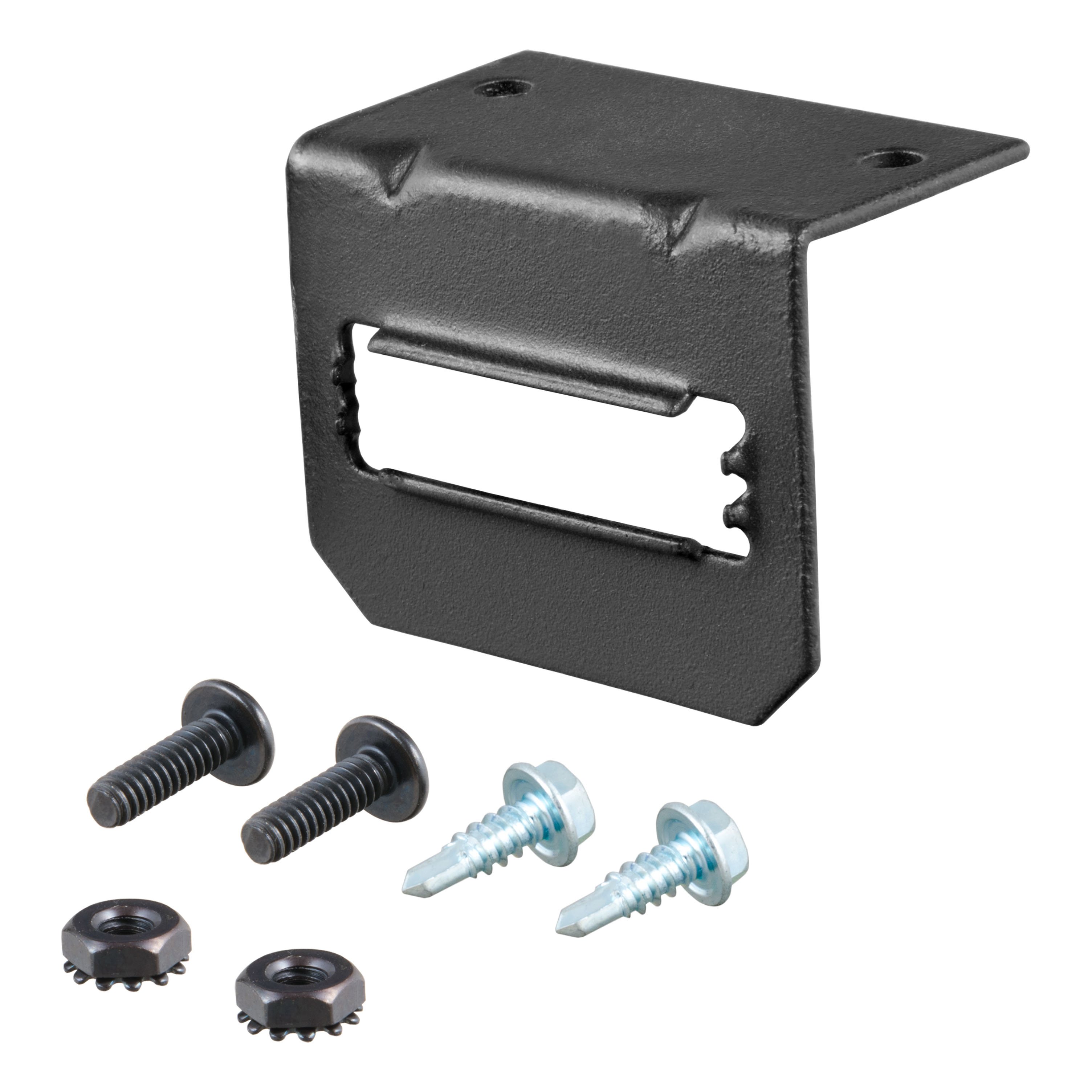
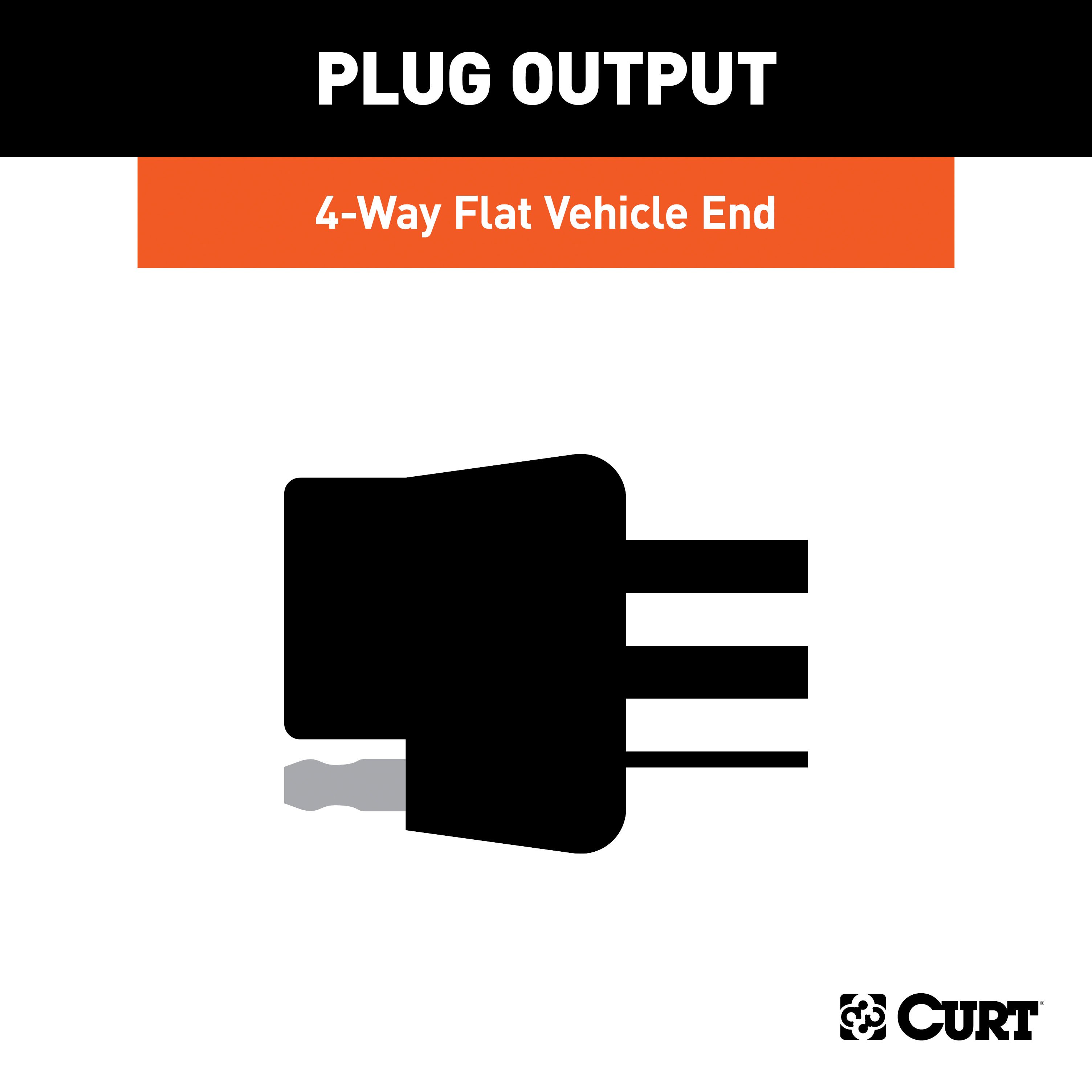
- Includes: Class 3 Trailer Tow Hitch, Custom Wiring, 4-Way to 5-Way Flat Adapter for Boat Trailer Surge Brakes, Connector Mounting Bracket for 5-Way Flat
Compatibility Chart
Description
Get Expert Help
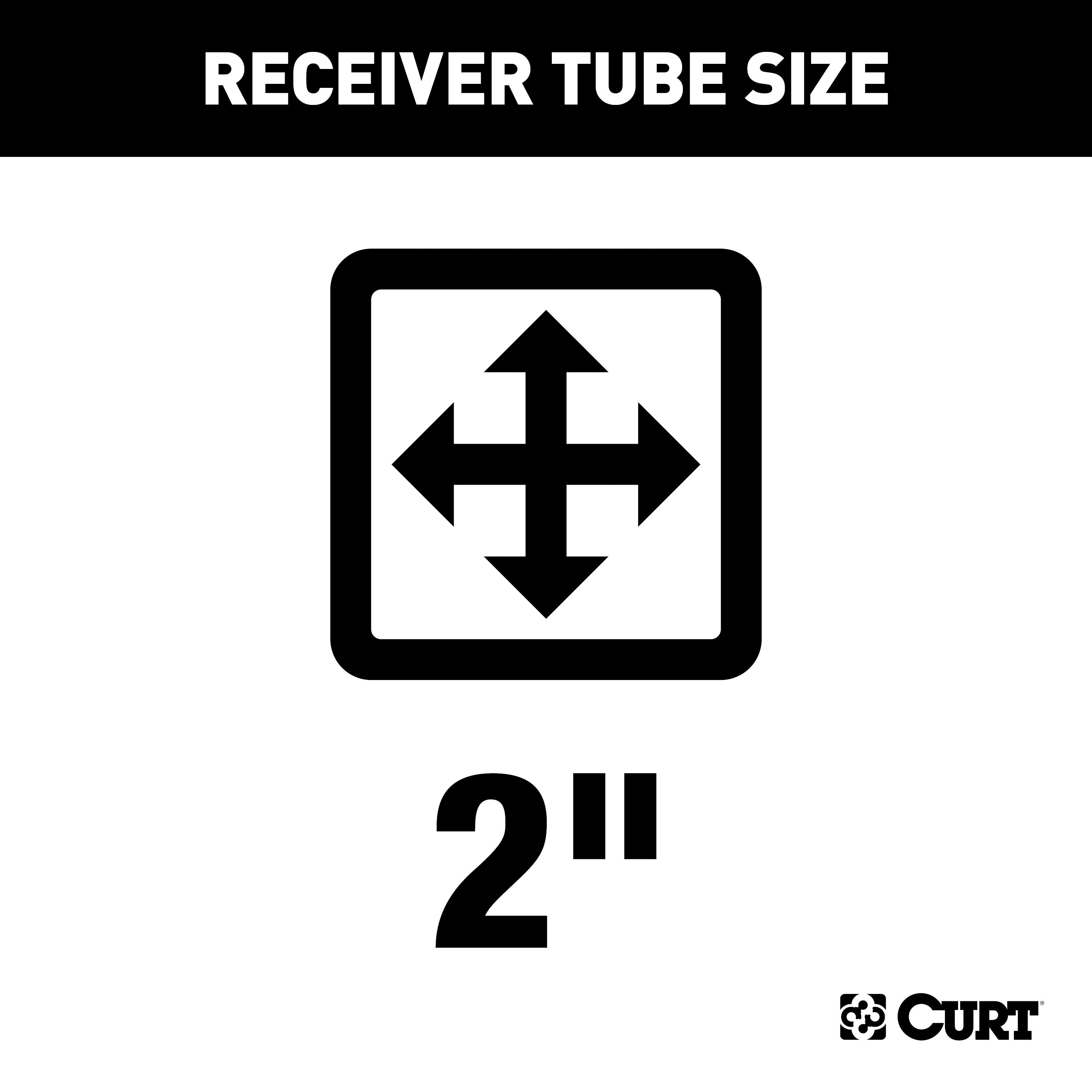
For 2013-2019 Ford Taurus Trailer Hitch + Wiring 5 Pin Fits All Models Curt 13379 2 inch Tow Receiver Install Notes
Installation Instructions for Ford Taurus SHO
Part Numbers:
- 13379
Tools Required:
- Ratchet
- Torque Wrench
- 10mm Socket
- 18mm Socket
- 19mm Socket
- Die Grinder
- 8" Socket Extension
- Pry Bar
- Spray Lubricant
- Safety Glasses
Step-by-Step Instructions:
-
Lower the Exhaust:
- Remove the (2) exhaust hanger brackets from the rubber isolators on each frame rail.
- Use a pry bar and spray lubricant as needed for easy removal.
-
Remove Exhaust Isolator Brackets:
- Remove the (2) bolts securing the driver-side exhaust isolator bracket using a 10mm socket.
- Remove the (2) bolts securing the passenger-side exhaust isolator bracket using an 18mm socket.
- Return the brackets and hardware to the vehicle owner.
-
Fishwire Hardware:
- On the driver side frame rail, fishwire a CM-SP10 spacer and a 1/2" carriage bolt through the access hole and out of the mounting hole.
- Repeat the process for the reverse fishwire method to position the hardware through the access holes on both frame rails.
-
Enlarge Rear Bumper Holes:
- Use a die grinder to enlarge the two holes on the rear bumper bracket for hardware installation.
- Refer to the Hole Enlargement Diagram for guidance.
-
Install Hitch Hardware:
- Raise the hitch into position and align the mounting holes.
- Insert and secure the hitch using the following hardware:
- (3) 1/2"-13 carriage bolts with 1/2" conical toothed washers
- (1) M12 hex bolt with a conical toothed washer
-
Install Handle Nut:
- On the rear bumper bracket, insert a 7/16" handle nut through the opening.
- Hand-tighten a 7/16" hex bolt with a 7/16" conical toothed washer through the enlarged hole.
- Enlarging the opening may ease installation.
-
Torque Fasteners:
- Torque all 1/2" hardware to 110 ft-lbs.
- Torque all M12 hardware to 79 ft-lbs.
- Torque all 7/16" hardware to 59 ft-lbs.
-
Reinstall the Exhaust:
- Reinstall the rubber exhaust isolators onto the muffler hangers in the hitch side plates.
- Raise the exhaust back into position and reinstall the exhaust hangers.
Hardware List:
- (3) 1/2"-13 x 1-1/4" Carriage Bolts
- (3) CM-SP10 Square Hole Spacers (0.250 x 1.00 x 2.50")
- (3) 1/2"-13 Hex Flange Nuts
- (1) M12 x 1.75 x 35 Hex Bolt
- (1) 1/2" Conical Toothed Washer
- (1) 7/16"-14 x 1-1/4" Hex Bolt
- (1) 7/16" Conical Toothed Washer
- (1) 7/16" Handle Nut
- (1) 1/2" Fishwire Tool
Safety Notes:
- Periodically check this receiver hitch to ensure all fasteners are tight and structural components are sound.
- Warning: Do not exceed the vehicle manufacturer’s recommended towing capacity.
- Non-trailer loads must be supported by 18050 stabilizing straps.
Specifications:
- Gross Load Capacity (Weight Carrying Hitch):
- 4,000 lbs. Trailer Weight
- 400 lbs. Tongue Weight
- Professional Install Time: 60 minutes
- Novice (DIY) Install Time: 90 minutes
Manufacturer Notes:
- Lowering the exhaust and enlarging bumper bracket holes are required for installation.
- Fishwiring hardware through the frame rails is necessary.
- Designed for use with Ball Mount #D-18 / 45518.
- For installation questions, call Technical Support at 1-877-287-8634.
End of Instructions
Installation Instructions for Ford Taurus SHO
Part Numbers:
- 13379
Tools Required:
- Ratchet
- Torque Wrench
- 10mm Socket
- 18mm Socket
- 19mm Socket
- Die Grinder
- 8" Socket Extension
- Pry Bar
- Spray Lubricant
- Safety Glasses
Step-by-Step Instructions:
-
Lower the Exhaust:
- Remove the (2) exhaust hanger brackets from the rubber isolators on each frame rail.
- Use a pry bar and spray lubricant as needed for easy removal.
-
Remove Exhaust Isolator Brackets:
- Remove the (2) bolts securing the driver-side exhaust isolator bracket using a 10mm socket.
- Remove the (2) bolts securing the passenger-side exhaust isolator bracket using an 18mm socket.
- Return the brackets and hardware to the vehicle owner.
-
Fishwire Hardware:
- On the driver side frame rail, fishwire a CM-SP10 spacer and a 1/2" carriage bolt through the access hole and out of the mounting hole.
- Repeat the process for the reverse fishwire method to position the hardware through the access holes on both frame rails.
-
Enlarge Rear Bumper Holes:
- Use a die grinder to enlarge the two holes on the rear bumper bracket for hardware installation.
- Attention: This is a summary of the installation procedure. For complete installation instructions, including diagrams and detailed information from the manufacturer, please download the full installation PDF.
-
Install Hitch Hardware:
- Raise the hitch into position and align the mounting holes.
- Insert and secure the hitch using the following hardware:
- (3) 1/2"-13 carriage bolts with 1/2" conical toothed washers
- (1) M12 hex bolt with a conical toothed washer
-
Install Handle Nut:
- On the rear bumper bracket, insert a 7/16" handle nut through the opening.
- Hand-tighten a 7/16" hex bolt with a 7/16" conical toothed washer through the enlarged hole.
-
Torque Fasteners:
- Torque all 1/2" hardware to 110 ft-lbs.
- Torque all M12 hardware to 79 ft-lbs.
- Torque all 7/16" hardware to 59 ft-lbs.
-
Reinstall the Exhaust:
- Reinstall the rubber exhaust isolators onto the muffler hangers in the hitch side plates.
- Raise the exhaust back into position and reinstall the exhaust hangers.
Hardware List:
- (3) 1/2"-13 x 1-1/4" Carriage Bolts
- (3) CM-SP10 Square Hole Spacers (0.250 x 1.00 x 2.50")
- (3) 1/2"-13 Hex Flange Nuts
- (1) M12 x 1.75 x 35 Hex Bolt
- (1) 1/2" Conical Toothed Washer
- (1) 7/16"-14 x 1-1/4" Hex Bolt
- (1) 7/16" Conical Toothed Washer
- (1) 7/16" Handle Nut
- (1) 1/2" Fishwire Tool
Warnings and Safety Information:
- Warning: Never exceed the vehicle manufacturer’s recommended towing capacity.
- Periodically inspect the hitch to ensure all fasteners remain tight and structural components are sound.
- Caution: Improper installation or failure to periodically inspect this product could result in serious injury.
Specifications:
- Gross Load Capacity (Weight Carrying Hitch):
- 4,000 lbs. Trailer Weight
- 400 lbs. Tongue Weight
- Professional Install Time: 60 minutes
- Novice (DIY) Install Time: 90 minutes
Additional Information:
- Lowering the exhaust and enlarging bumper bracket holes are required for installation.
- Fishwiring hardware through the frame rails is necessary.
- For technical support and assistance, our team of experts is available to help. You can reach our tech support by visiting www.trailerjacks.com or calling 877-869-6690.
Warranty Information:
- The warranty duration and coverage details are outlined in the full installation PDF.
- For complete warranty instructions, please download the full installation PDF.
End of Instructions
Installation Instructions for Ford Taurus and Ford Explorer
Part Number:
- 56093
Tools Required:
- Ratchet
- 8mm socket
- Panel trim removal tool
- Wire crimper
- Paint marker
- Socket extension
- Cutting tool
- Heat gun
- Wire stripper
- Electrical tape
Electrical Ratings:
- Signal Circuits: 3.0 amps per side
- Tail/Running Circuits: 6.0 amps total
Wiring Access Location:
- Passenger Cars (P):
- P3: Behind driver-side taillight housing, inside trunk
- P4: Behind passenger-side taillight housing, inside trunk
- SUVs and Vans (S):
- S3: Behind driver-side rear access panel
- S4: Behind passenger-side rear access panel
Ford Taurus Instructions:
-
Disconnect the Battery:
- Locate the vehicle's battery in the engine compartment on the driver side.
- Disconnect the negative battery terminal and secure it away from the battery during installation.
-
Prepare the Trunk:
- Open the trunk, remove floor coverings, and expose the spare tire.
- Use a panel trim removal tool to remove the scuff panel by pulling outward and upward to release alignment tabs.
-
Access the Taillight Connectors:
- Remove three plastic fasteners securing the felt trunk liner.
- Pull back the felt liner on the driver side to expose the taillight wiring harness connectors.
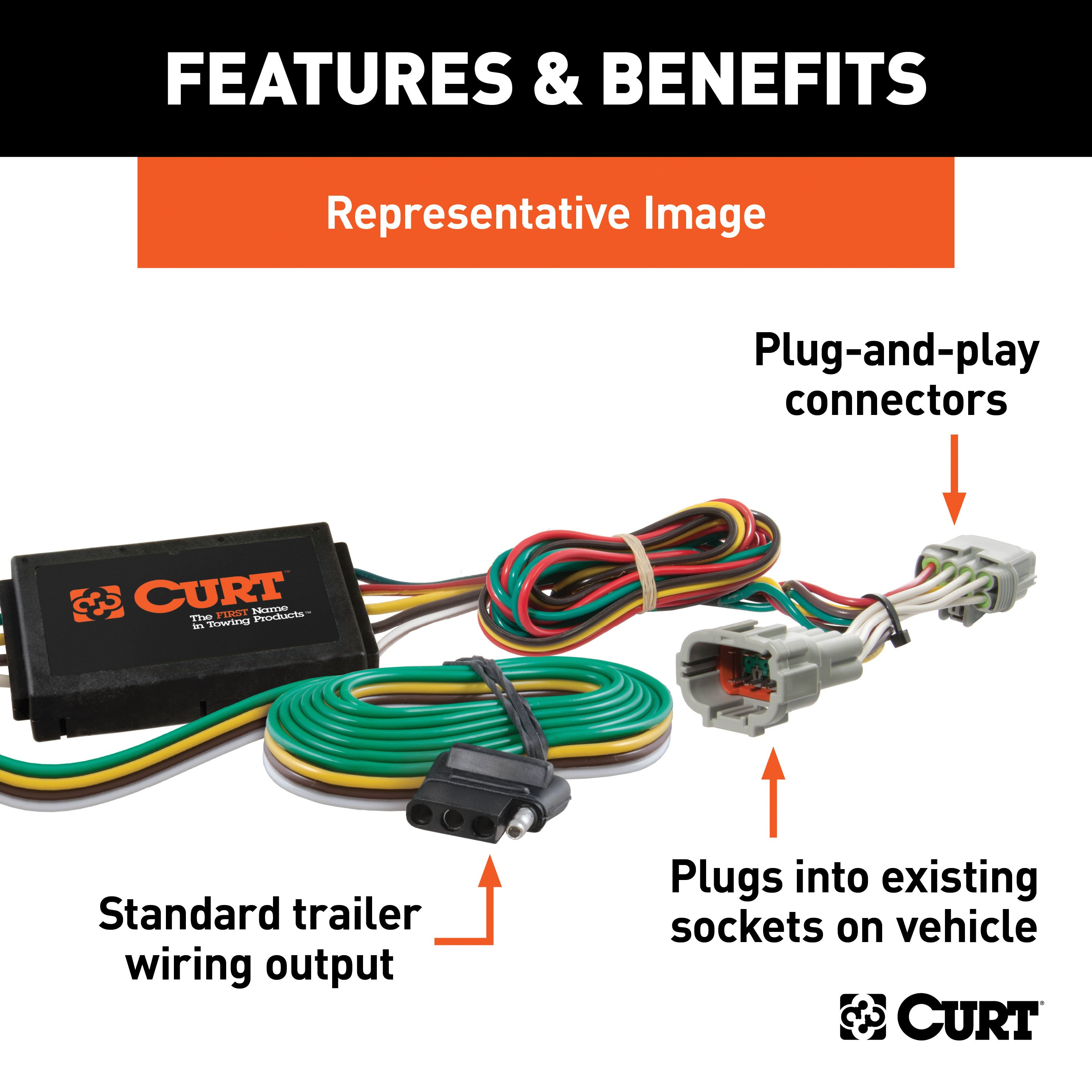
- Separate the connectors and insert the T-connector end with the yellow wire between them, ensuring the locking tabs engage.
-
Ground the White Wire:
- Locate a suitable grounding point near the connector, such as an existing screw or drill a 3/32" pilot hole.
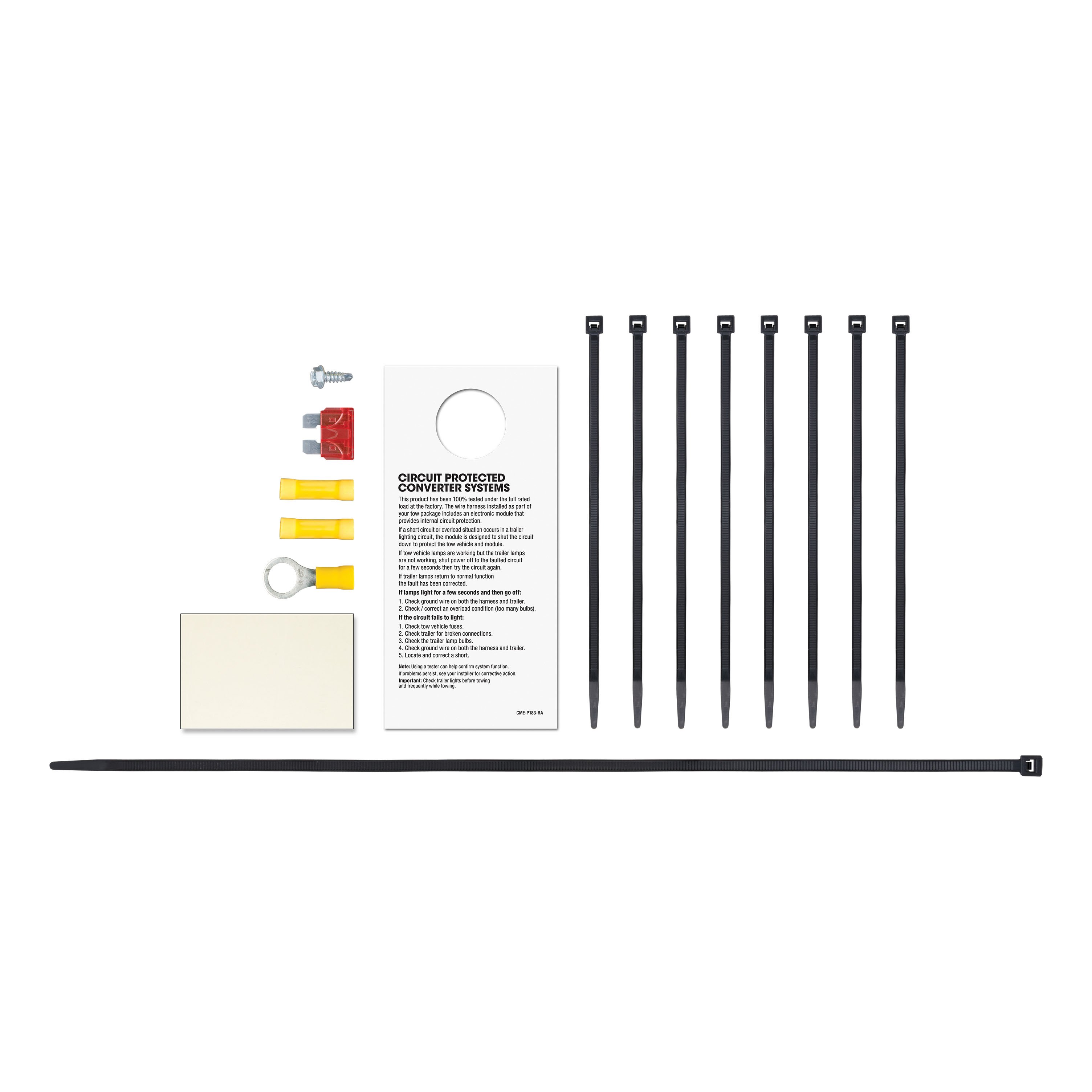
- Secure the white wire using the provided eyelet and screw.
-
Route the Green Wire:
- Route the green wire along the back of the vehicle under the scuff plate to the passenger side.
- Repeat step 3 for the passenger-side taillight with the green wire.
-
Mount the Converter Box:
- Adhere the black converter box to the vehicle's frame using the provided double-sided tape.
-
Route the Black Power Wire:
- Route the black power wire from the vehicle battery as described in the "Powered Converter Lead Instruction Sheet."
-
Reassemble and Test:
- Reinstall all removed components and reconnect the negative battery terminal.
- Test the system with a test light or a properly wired trailer.
Ford Explorer Instructions:
For Explorer (10th VIN B, C, D):
-
Disconnect the Battery:
- Locate the battery in the engine compartment on the driver side.
- Disconnect the negative battery terminal and secure it away from the battery during installation.
-
Remove the Rear Interior Panels:
- Open the tailgate and fold down the third-row seats (if equipped).
- Use a trim panel removal tool to remove the scuff panel and side panels to access the taillight housings.
-
Access the Taillight Connectors:
- Remove the rear trim and pull back to expose the taillight wiring harness.
- Insert the T-connector end with the yellow wire between the driver-side connectors.
-
Ground the White Wire:
- Locate a suitable grounding point near the connector, such as an existing screw or drill a 3/32" pilot hole.
- Secure the white wire using the provided ring terminal and screw.
-
Route the Green Wire:
- Route the green wire along the rear trim to the passenger side.
- Repeat step 3 for the passenger-side taillight using the green wire.
-
Mount the Converter Box:
- Adhere the black converter box to the vehicle's frame using the provided double-sided tape.
-
Route the Black Power Wire:
- Route the black power wire from the vehicle battery as described in the Powered Converter Lead Instruction Sheet.
-
Reassemble and Test:
- Secure all loose wires with the provided cable ties and install the dust cover.
- Reconnect the battery and test for functionality.
For Explorer (10th VIN L):
-
Access Rear Panels and Taillights:
- Open the rear hatch and use a panel trim removal tool to access the interior side panels.
- Pull back the panels and locate the taillight connectors.
-
Install the T-Connector:
- Follow the same steps as VIN
B, C, Dto install the T-connector and secure the wiring harness.
- Follow the same steps as VIN
-
Route Wires and Secure:
- Route all wires securely to prevent damage, following the same procedure as VIN
B, C, D. - Test the wiring and ensure proper grounding.
- Route all wires securely to prevent damage, following the same procedure as VIN
Safety Notes:
- Warning: Verify no hidden components exist before drilling to avoid damage or injury.
- Ensure all connections are secure, and do not exceed the product or vehicle lamp load ratings.
- The battery connection must be fuse-protected (10-amp max) to prevent overheating, fire, or loss of warranty.
Installation Instructions for Passenger Cars and SUVs
Part Number:
- 56093
Tools Required:
- Ratchet
- 8mm socket
- Panel trim removal tool
- Wire crimper
- Paint marker
- Socket extension
- Cutting tool
- Heat gun
- Wire stripper
- Electrical tape
Electrical Ratings:
- Signal Circuits: 3.0 amps per side
- Tail/Running Circuits: 6.0 amps total
Wiring Access Location:
- Passenger Cars (P):
- P3: Behind driver-side taillight housing, inside trunk
- P4: Behind passenger-side taillight housing, inside trunk
- SUVs and Vans (S):
- S3: Behind driver-side rear access panel
- S4: Behind passenger-side rear access panel
Passenger Car Instructions:
-
Disconnect the Battery:
- Locate the vehicle's battery in the engine compartment on the driver side.
- Disconnect the negative battery terminal and secure it away from the battery during installation.
-
Prepare the Trunk:
- Open the trunk, remove floor coverings, and expose the spare tire.
- Use a panel trim removal tool to remove the scuff panel by pulling outward and upward to release alignment tabs.
-
Access the Taillight Connectors:
- Remove three plastic fasteners securing the felt trunk liner.
- Pull back the felt liner on the driver side to expose the taillight wiring harness connectors.
- Separate the connectors and insert the T-connector end with the yellow wire between them, ensuring the locking tabs engage.
-
Ground the White Wire:
- Locate a suitable grounding point near the connector, such as an existing screw or drill a 3/32" pilot hole.
- Secure the white wire using the provided eyelet and screw.
-
Route the Green Wire:
- Route the green wire along the back of the vehicle under the scuff plate to the passenger side.
- Repeat step 3 for the passenger-side taillight with the green wire.
-
Mount the Converter Box:
- Adhere the black converter box to the vehicle's frame using the provided double-sided tape.
-
Route the Black Power Wire:
- Route the black power wire from the vehicle battery as described in the "Powered Converter Lead Instruction Sheet."
-
Reassemble and Test:
- Reinstall all removed components and reconnect the negative battery terminal.
- Test the system with a test light or a properly wired trailer.
SUV Instructions:
For VIN B, C, D:
-
Disconnect the Battery:
- Locate the battery in the engine compartment on the driver side.
- Disconnect the negative battery terminal and secure it away from the battery during installation.
-
Remove the Rear Interior Panels:
- Open the tailgate and fold down the third-row seats (if equipped).
- Use a trim panel removal tool to remove the scuff panel and side panels to access the taillight housings.
-
Access the Taillight Connectors:
- Remove the rear trim and pull back to expose the taillight wiring harness.
- Insert the T-connector end with the yellow wire between the driver-side connectors.
-
Ground the White Wire:
- Locate a suitable grounding point near the connector, such as an existing screw or drill a 3/32" pilot hole.
- Secure the white wire using the provided ring terminal and screw.
-
Route the Green Wire:
- Route the green wire along the rear trim to the passenger side.
- Repeat step 3 for the passenger-side taillight using the green wire.
-
Mount the Converter Box:
- Adhere the black converter box to the vehicle's frame using the provided double-sided tape.
-
Route the Black Power Wire:
- Route the black power wire from the vehicle battery as described in the Powered Converter Lead Instruction Sheet.
-
Reassemble and Test:
- Secure all loose wires with the provided cable ties and install the dust cover.
- Reconnect the battery and test for functionality.
For VIN L:
-
Access Rear Panels and Taillights:
- Open the rear hatch and use a panel trim removal tool to access the interior side panels.
- Pull back the panels and locate the taillight connectors.
-
Install the T-Connector:
- Follow the same steps as VIN
B, C, Dto install the T-connector and secure the wiring harness.
- Follow the same steps as VIN
-
Route Wires and Secure:
- Route all wires securely to prevent damage, following the same procedure as VIN
B, C, D. - Test the wiring and ensure proper grounding.
- Route all wires securely to prevent damage, following the same procedure as VIN
Safety Notes:
- Warning: Verify no hidden components exist before drilling to avoid damage or injury.
- Ensure all connections are secure, and do not exceed the product or vehicle lamp load ratings.
- The battery connection must be fuse-protected (10-amp max) to prevent overheating, fire, or loss of warranty.
Additional Information:
- Attention: This is a summary of the installation procedure. For complete installation instructions, including diagrams and detailed information from the manufacturer, please download the full installation PDF.
Technical Support:
- For technical support and assistance, our team of experts is available to help. You can reach our tech support by visiting www.trailerjacks.com or calling 877-869-6690.
Warranty Information:
- For complete warranty instructions, please download the full installation PDF.
Installation Instructions for 4-Way to 5-Way Adapter
Tools Required:
- Wire Crimpers
- Wire Cutters
- Test Light or Multimeter
- Quick Splice Connector (provided)
- Additional Wire (if needed for reverse light connection)
- Cable Ties (optional)
- Silicone Sealant (optional)
Overview:
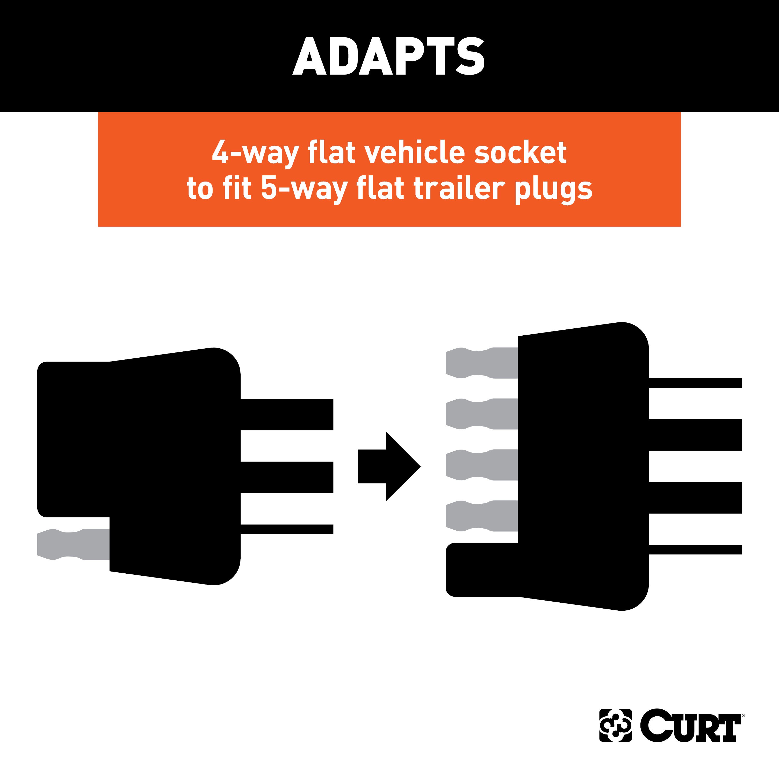
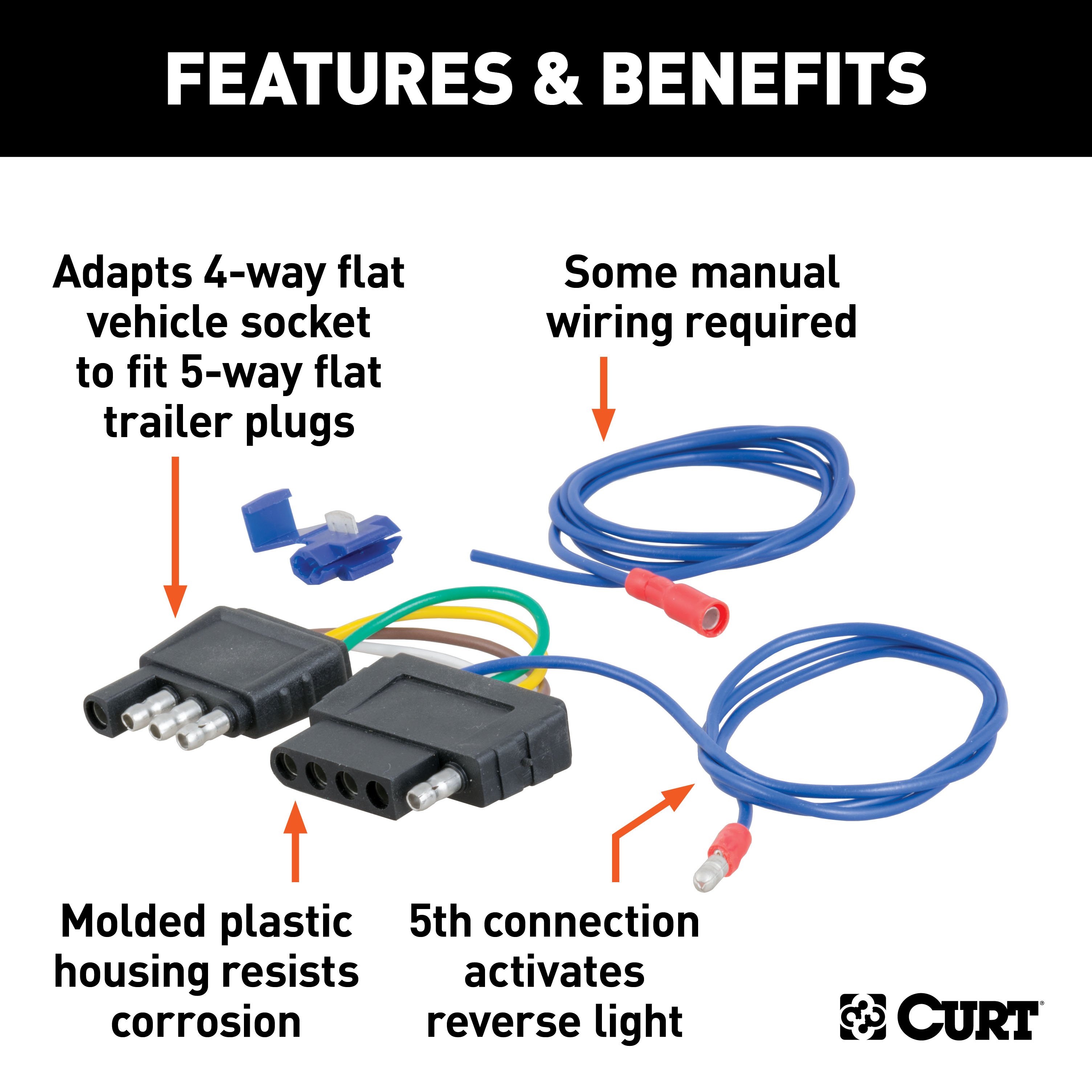
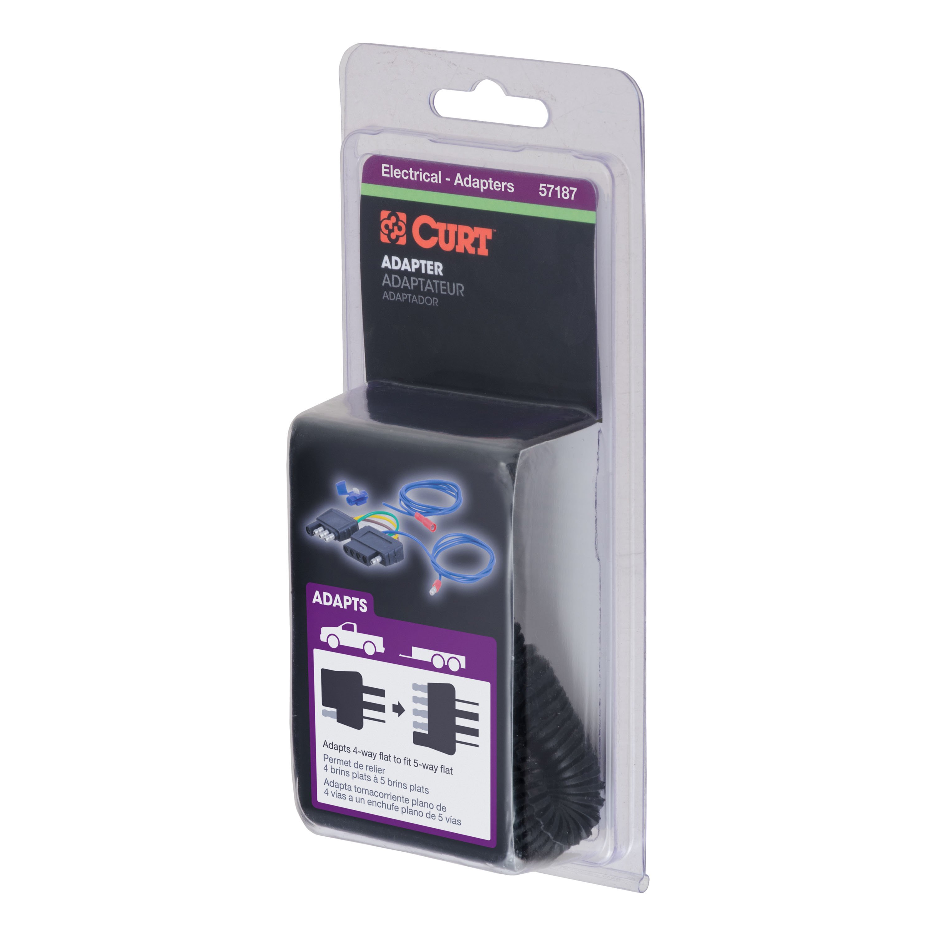
This adapter converts your 4-way flat trailer connector to a 5-way flat, adding reverse light functionality for trailers with reverse lights or surge brake lockout systems.
Step-by-Step Instructions:
1. Mount the Adapter:
- Select a suitable mounting location near the hitch and securely install the adapter.
2. Connect the 4-Way Plug:
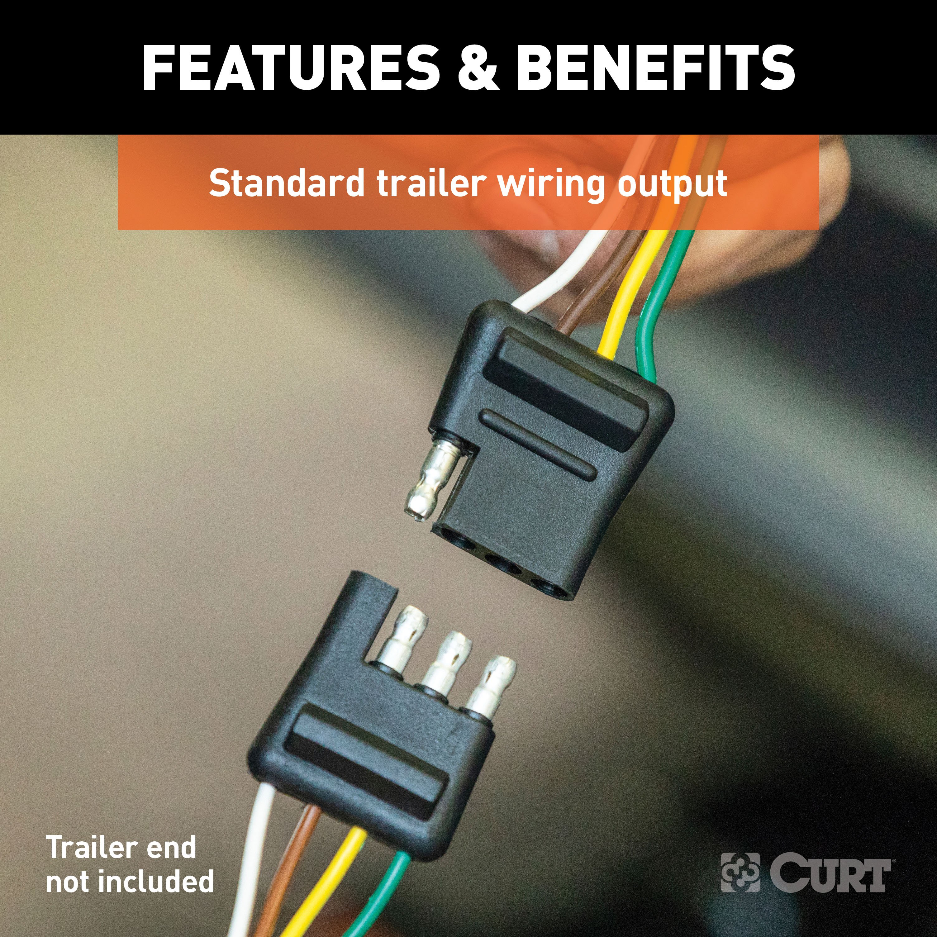
- Plug the 4-way flat connector from the adapter into the existing 4-way flat connector on your vehicle.
- This connection provides tail lights, left turn, right turn, and brake light functions.
3. Ground the Adapter:
- Locate a solid ground point near the adapter, such as the vehicle frame.
- Clean the surface to ensure proper contact.
- Secure the white ground wire from the adapter using the provided eyelet and a self-tapping screw.
4. Connect the Reverse Light Circuit:
-
Locate the Reverse Light Wire:
- Identify the reverse light circuit on your vehicle, typically found near the tail light assembly.
- Use the provided quick splice connector to attach the adapter's blue wire to the vehicle’s reverse light circuit.
-
Extend the Blue Wire (If Needed):
- If the adapter's blue wire is too short, splice in additional wire to reach the reverse light circuit.
- Route the wire safely, avoiding hot or moving parts, and secure it with cable ties.
-
Seal the Connection:
- If routing the wire through a grommet, seal any openings with silicone to prevent water ingress.
5. Secure the Wiring:
- Use cable ties to secure all wires and prevent them from hanging loosely or contacting sharp edges.
6. Test the Adapter:
- Plug the adapter into your trailer’s 5-way flat connector or use a test light to verify functionality:
- Brown Wire: Tail lights (solid when headlights are on).
- Yellow Wire: Left turn signal and brake light (flashes with turn signal).
- Green Wire: Right turn signal and brake light (flashes with turn signal).
- Blue Wire: Reverse light (active when the vehicle is in reverse).
- White Wire: Ground (continuity with the vehicle's ground).
Notes:
- This adapter is designed specifically for trailers requiring a reverse light or surge brake lockout circuit.
- Ensure all connections are secure to avoid intermittent functionality.
- Always follow safety guidelines during installation and verify all circuits before use.
Warning: Improper installation or overloaded circuits can result in damage or fire. Test all connections carefully.
Warranty Information:
For complete warranty instructions, please download the full installation PDF.
For technical support and assistance, our team of experts is available to help. You can reach our tech support by visiting www.trailerjacks.com or calling 877-869-6690.


