Product Details
- Brand: Curt
- Model: 14374 58044-CH3215
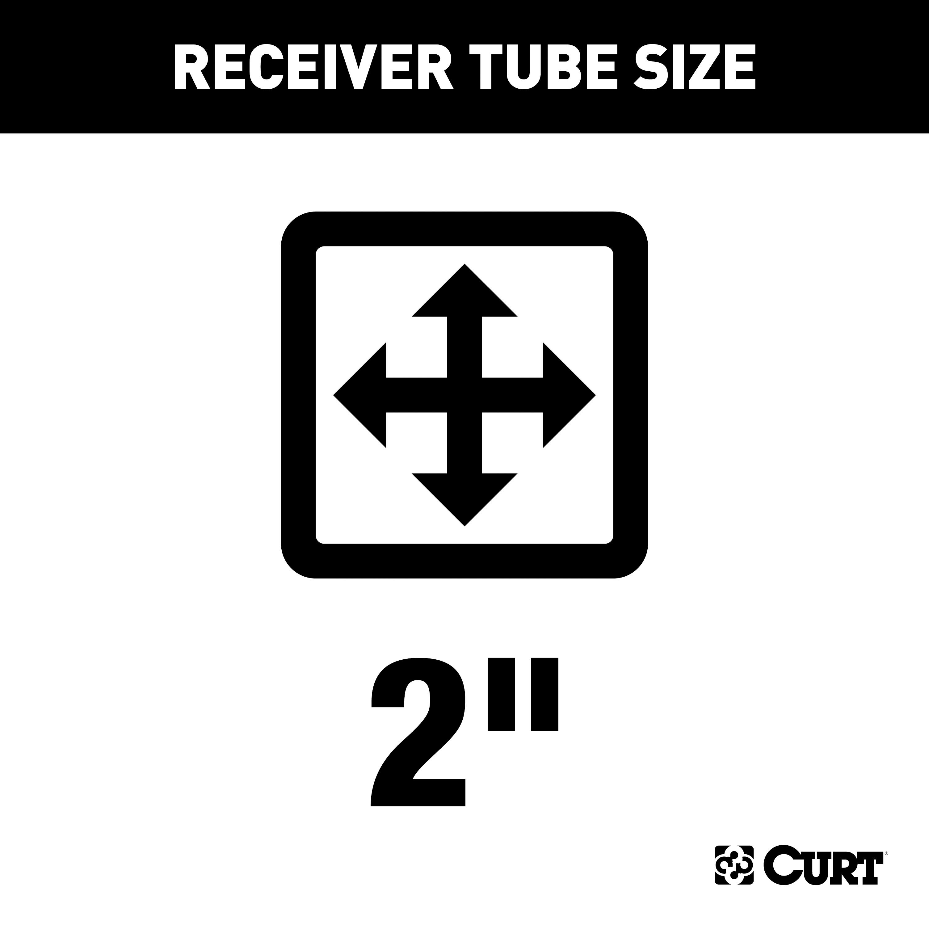
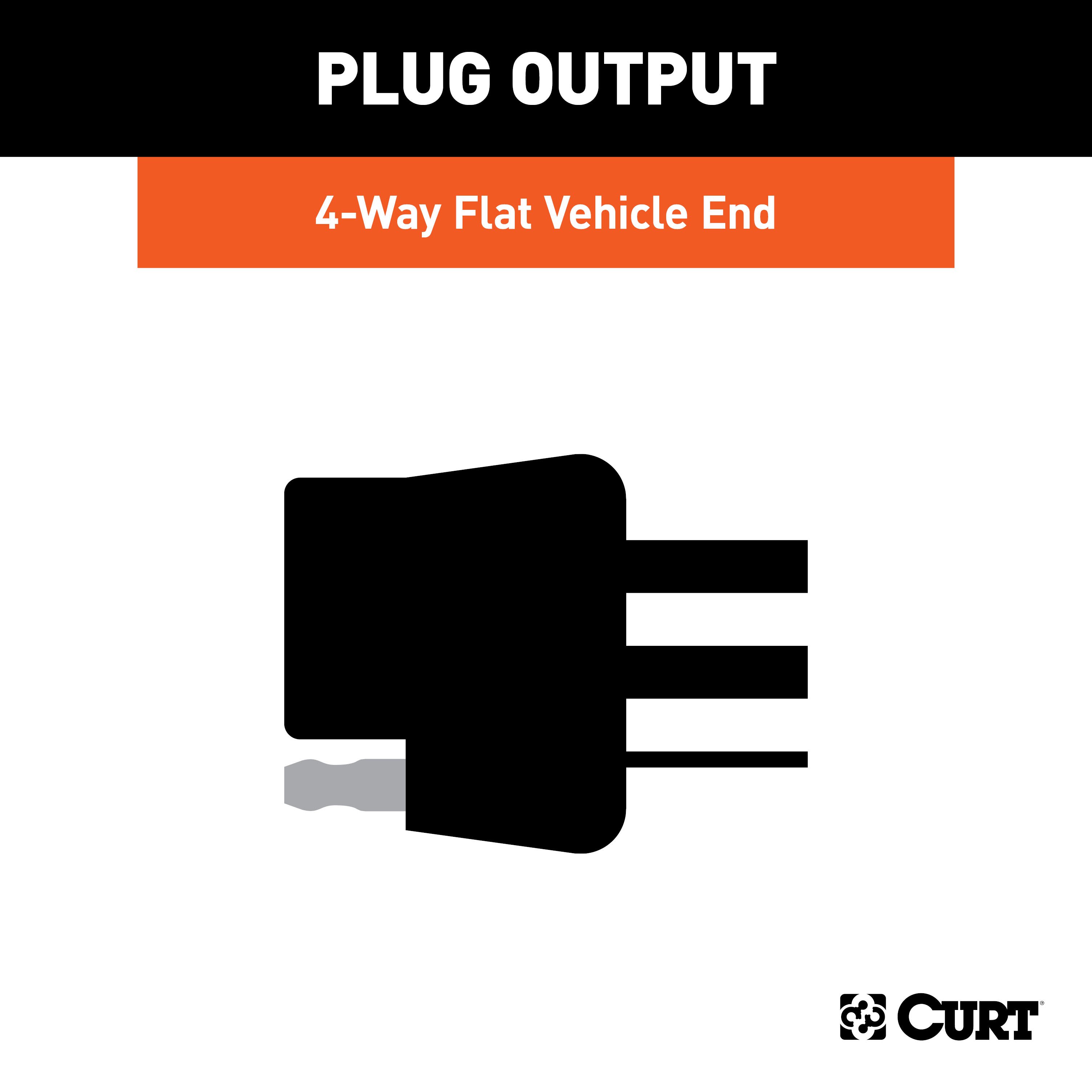
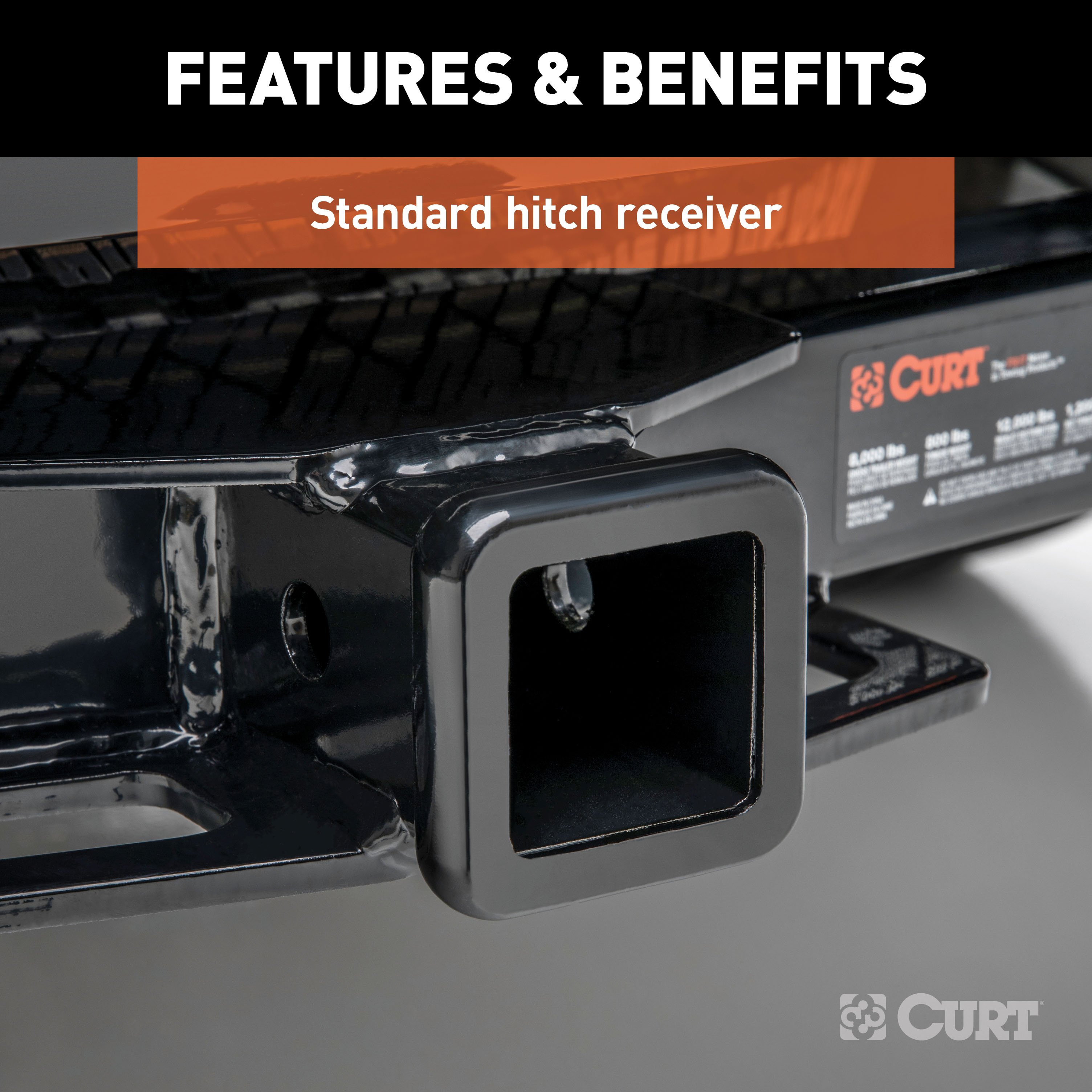
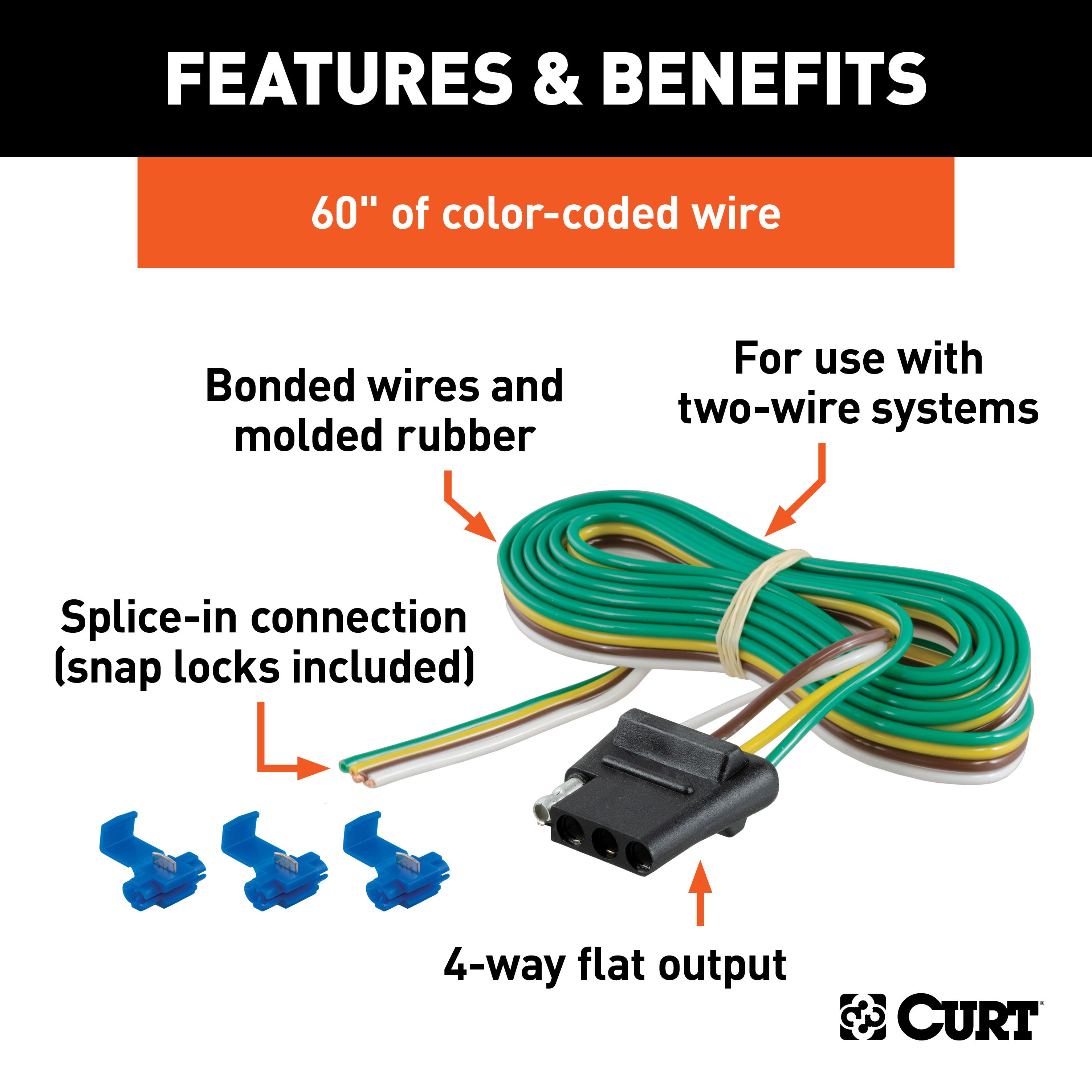
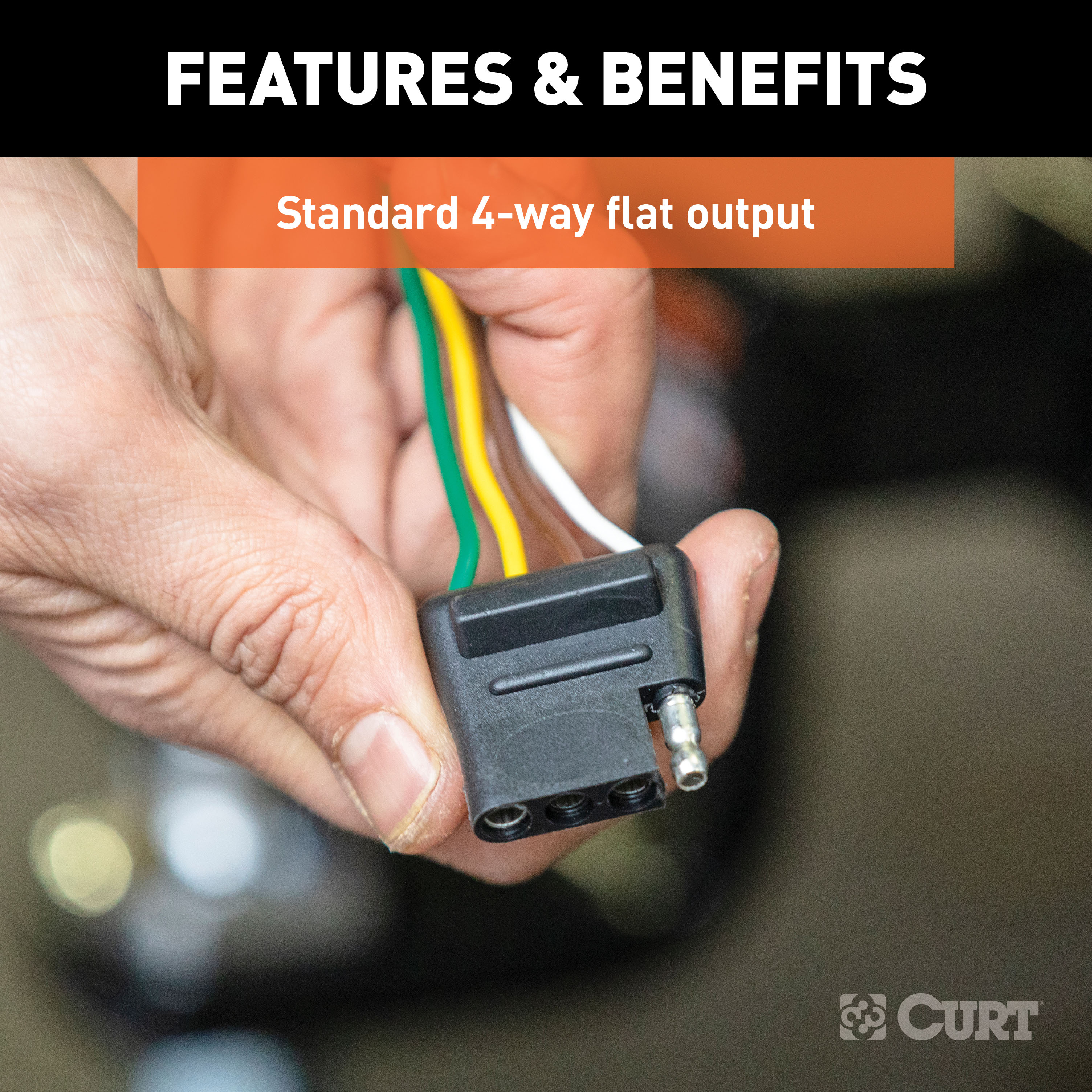
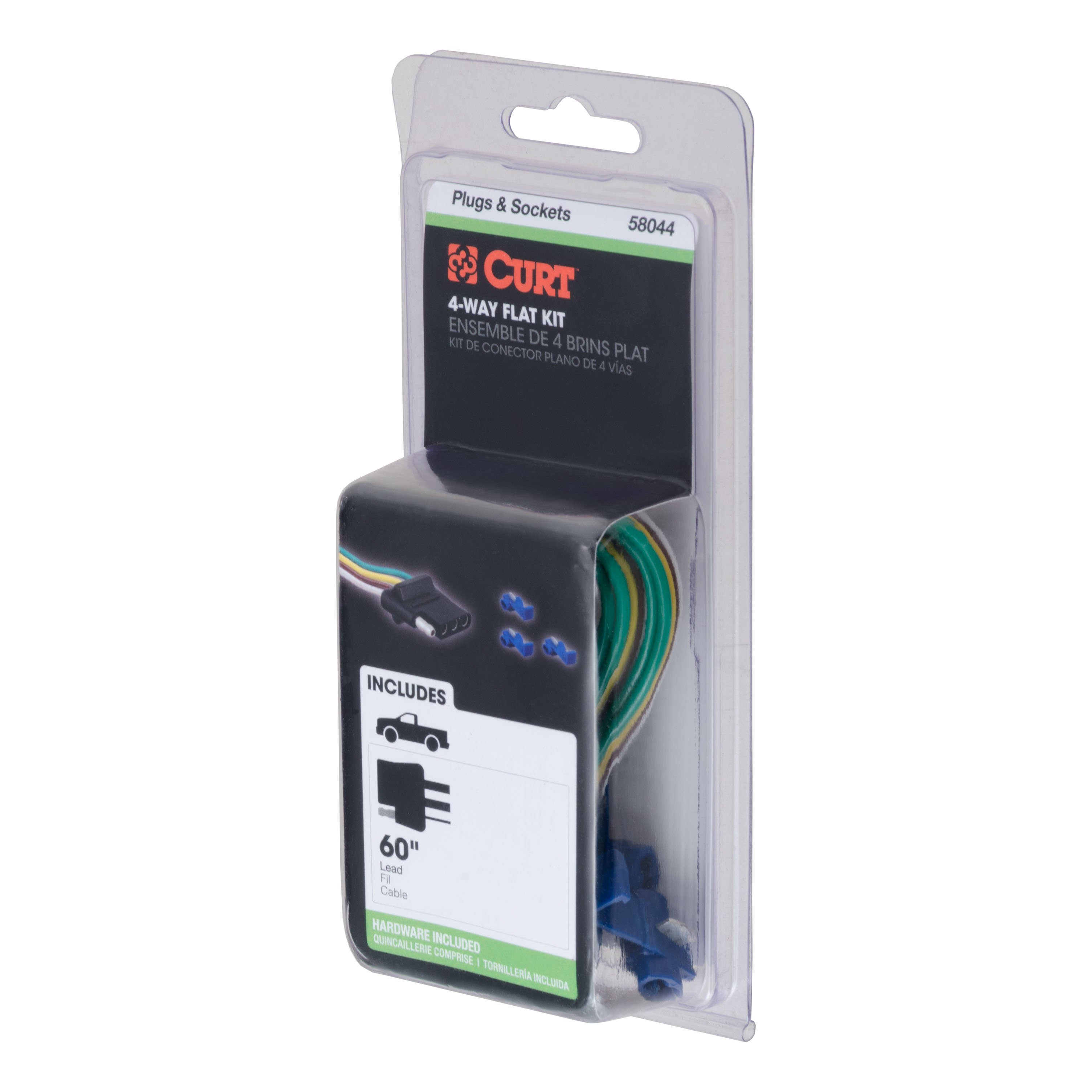
- Includes: Class 4 Trailer Tow Hitch, 4-Way Flat Connector Socket with 60" Wires
Compatibility Chart
Description
Get Expert Help
For 2013-2014 Ram 1500 Trailer Hitch + Wiring 4 Pin Except factory receiver Curt 14374 58044 2 inch Tow Receiver Install Notes
Installation Instructions for Dodge Ram 1500 Without OEM Hitch
Part Numbers:
- 14374
Tools Required:
- Socket Wrench
- Torque Wrench
- 21mm Socket
- 3/4" Socket
- 6" Socket Extension
Hardware List:
- Carriage Bolt: 1/2-13 x 1-1/2", Grade 8, YZ (Qty: 4)
- Flange Nut: 1/2-13 UNC, Grade 8, YZ (Qty: 4)
- Square Hole Spacer: 0.188 x 1.00 x 3.00" (CM-SP40) (Qty: 2)
- Square Hole Spacer: 0.250 x 1.50 x 3.00" (CM-SP4) (Qty: 2)
- Fishwire: 1/2" x 30" (Qty: 1)
Step-by-Step Instructions:
-
Lower Spare Tire:
- Lower the spare tire for ease of installation.
-
Remove Existing Bolts:
- Remove the M14 bolts securing the bumper beam to the frame rails on both sides.
- Save these bolts for use in Step 6.
-
Reverse Fishwire Carriage Bolts:
- Reverse fishwire the 1/2-13 x 1-1/2" carriage bolts and CM-SP40 spacers through the large round holes in the driver and passenger-side frame rails.
- Follow the Reverse Pull Fishwire Technique diagram for proper execution.
-
Fishwire Carriage Bolts Through Bumper Beam:
- Fishwire the remaining 1/2-13 x 1-1/2" carriage bolts and CM-SP4 spacers through the ends of the bumper beam.
- Pull them out through the slot at the front of the bumper beam. Refer to the Fishwire Technique Diagram for guidance.
-
Raise the Hitch into Position:
- Position the hitch into place, aligning it with the carriage bolts in the frame and bumper beam.
- Loosely install the provided 1/2-13 hex flange nuts onto the carriage bolts.
-
Reinstall Existing Bolts:
- Reinstall the M14 bolts removed in Step 2 to secure the bumper beam and hitch to the frame.
-
Torque Fasteners:
- Torque all 1/2" hardware to 110 lb-ft.
- Torque all M14 hardware to 126 lb-ft.
-
Raise Spare Tire:
- Return the spare tire to its original position.
Safety Notes:
- No Drilling Required: Installation uses existing holes in the bumper beam and frame rails.
- Fishwire Technique: Use the fishwire tool carefully to avoid losing hardware inside the frame rails.
- Periodically inspect the hitch to ensure all fasteners remain tight and components are structurally sound.
Specifications:
- Gross Load Capacity (Weight Carrying Hitch):
- Trailer Weight: 10,000 lbs
- Tongue Weight: 1,000 lbs
- Gross Load Capacity (Weight Distribution Hitch):
- Trailer Weight: 12,000 lbs
- Tongue Weight: 1,200 lbs
- Hitch Weight: 49 lbs
Installation Time:
- Professional: 30 minutes
- Novice (DIY): 60 minutes
Manufacturer Notes:
- For installation questions, contact Technical Support at 1-877-287-8634.
- Product Warranty: Curt Manufacturing Inc. guarantees this product to be free from defects in material and workmanship.
Warning: Do not exceed the vehicle manufacturer's recommended towing capacity.
Installation Instructions for Dodge Ram 1500 Without OEM Hitch
Part Numbers:
- 14374
Tools Required:
- Socket Wrench
- Torque Wrench
- 21mm Socket
- 3/4" Socket
- 6" Socket Extension
Hardware List:
- Carriage Bolt: 1/2-13 x 1-1/2", Grade 8, YZ (Qty: 4)
- Flange Nut: 1/2-13 UNC, Grade 8, YZ (Qty: 4)
- Square Hole Spacer: 0.188 x 1.00 x 3.00" (Qty: 2)
- Square Hole Spacer: 0.250 x 1.50 x 3.00" (Qty: 2)
- Fishwire: 1/2" x 30" (Qty: 1)
Step-by-Step Instructions:
-
Lower Spare Tire:
- Lower the spare tire for ease of installation.
-
Remove Existing Bolts:
- Remove the M14 bolts securing the bumper beam to the frame rails on both sides.
- Save these bolts for use in Step 6.
-
Reverse Fishwire Carriage Bolts:
- Reverse fishwire the 1/2-13 x 1-1/2" carriage bolts and spacers through the large round holes in the driver and passenger-side frame rails.
- Follow the Reverse Pull Fishwire Technique diagram for proper execution.
-
Fishwire Carriage Bolts Through Bumper Beam:
- Fishwire the remaining 1/2-13 x 1-1/2" carriage bolts and spacers through the ends of the bumper beam.
- Pull them out through the slot at the front of the bumper beam. Refer to the Fishwire Technique Diagram for guidance.
-
Raise the Hitch into Position:
- Position the hitch into place, aligning it with the carriage bolts in the frame and bumper beam.
- Loosely install the provided 1/2-13 hex flange nuts onto the carriage bolts.
-
Reinstall Existing Bolts:
- Reinstall the M14 bolts removed in Step 2 to secure the bumper beam and hitch to the frame.
-
Torque Fasteners:
- Torque all 1/2" hardware to 110 lb-ft.
- Torque all M14 hardware to 126 lb-ft.
-
Raise Spare Tire:
- Return the spare tire to its original position.
Safety Notes:
- No Drilling Required: Installation uses existing holes in the bumper beam and frame rails.
- Fishwire Technique: Use the fishwire tool carefully to avoid losing hardware inside the frame rails.
- Periodically inspect the hitch to ensure all fasteners remain tight and components are structurally sound.
Specifications:
- Gross Load Capacity (Weight Carrying Hitch):
- Trailer Weight: 10,000 lbs
- Tongue Weight: 1,000 lbs
- Gross Load Capacity (Weight Distribution Hitch):
- Trailer Weight: 12,000 lbs
- Tongue Weight: 1,200 lbs
- Hitch Weight: 49 lbs
Installation Time:
- Professional: 30 minutes
- Novice (DIY): 60 minutes
Manufacturer Notes:
Attention: This is a summary of the installation procedure. For complete installation instructions, including diagrams and detailed information from the manufacturer, please download the full installation PDF.
For technical support and assistance, our team of experts is available to help. You can reach our tech support by visiting www.trailerjacks.com or calling 877-869-6690.
Warranty Information:
- Warranty covers defects in material and workmanship at the time of purchase. For complete warranty instructions, please download the full installation PDF.
Warning: Do not exceed the vehicle manufacturer's recommended towing capacity.
Installation Instructions for Taillight Wiring Converter
Part Numbers:
- 58044
Wiring Access Locations:
- S1: Behind driver’s side taillight housing
- S2: Behind passenger’s side taillight housing
- S3: Behind driver’s side rear access panel
- S4: Behind passenger’s side rear access panel
- T1: Behind driver’s side taillight housing
- T2: Behind passenger’s side taillight housing
- T3: Behind driver’s side rear bumper
- T5: Behind passenger’s side rear bumper
Tools Required:
- Test light
Step-by-Step Instructions:
- Locate the vehicle's taillight wiring using the typical locations based on the vehicle type.
- Using a test light, identify the corresponding wires for:
- Left turn signal
- Right turn signal
- Tail lights
- Brake lights
- Temporarily disconnect the vehicle's negative battery cable.
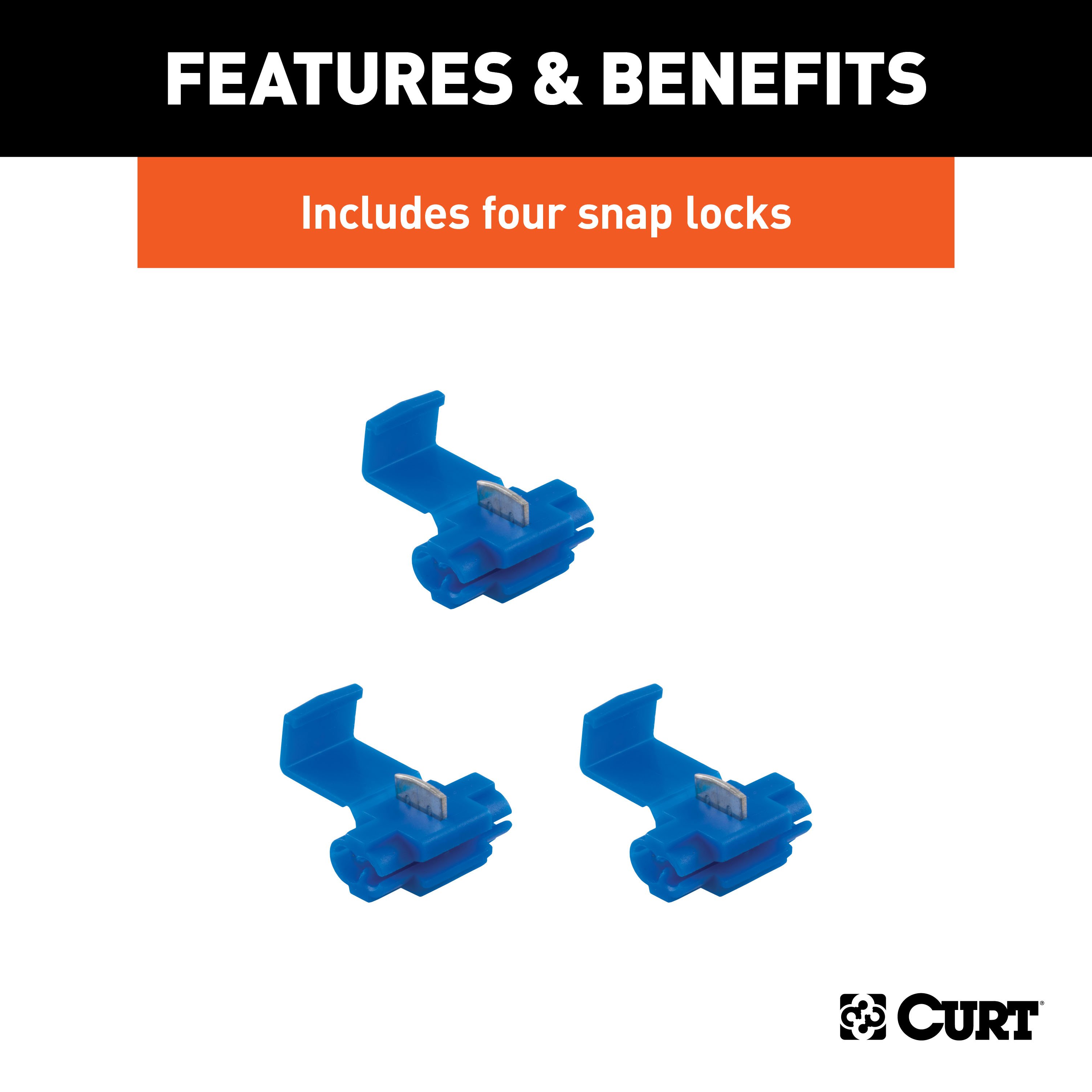
- Using wire taps, connect the converter input wires to the vehicle harness wires:
- Brown Wire: Tail Light Circuit
- Yellow Wire: Left Turn/Brake Circuit
- Green Wire: Right Turn/Brake Circuit
- Locate a system ground wire:
- Use a terminal ring or tap into an existing ground wire.
- Test the installation:
- If testing with a test light:
- Attach the test light ground lead to the exposed ground terminal of the 4-flat end.
- Activate the left turn, right turn, tail, and brake lights on the vehicle one at a time.
- Probe the 4-flat end receptacles to confirm functionality.
- If testing with a trailer:
- Mate the 4-flat with the trailer and repeat the same tests.
- If any trailer light functions fail, recheck the vehicle wiring with a circuit tester.
- If testing with a test light:
Hardware List:
- 4-flat connector (60” car end):
- White Wire: To Ground
- Green Wire: To Right Turn Signal
- Yellow Wire: To Left Turn Signal
- Brown Wire: To Taillight Signal
Safety Notes:
- Ensure the product is only used on 2-wire, 12-volt negative ground systems.
- Double-check all connections and secure wires to avoid potential hazards.
Specifications:
- Compliance: Designed for 2-wire 12V systems with a negative ground.
- Ensure proper alignment and secure attachment to avoid wiring faults.
Additional Information:
- Attention: This is a summary of the installation procedure. For complete installation instructions, including diagrams and detailed information from the manufacturer, please download the full installation PDF.
Technical Support:
- For technical support and assistance, our team of experts is available to help. You can reach our tech support by visiting www.trailerjacks.com or calling 877-869-6690.
Warranty:
- Warranty Duration: [Insert warranty period]
- Coverage Details: [Insert coverage details]
- For complete warranty information, please download the full installation PDF.


