Product Details
- Brand: Curt
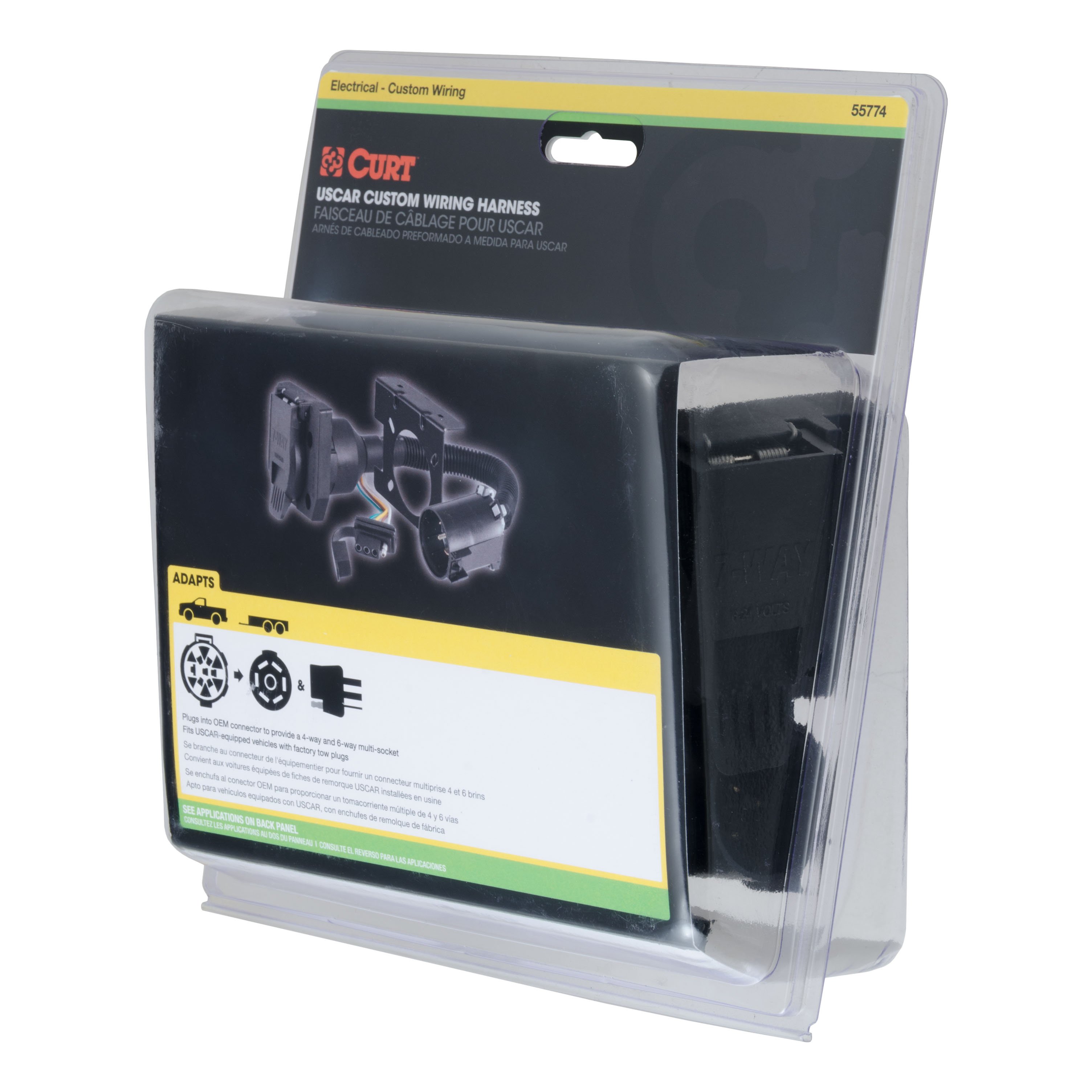
- Model: 13304 51382 55774 45042 51160-CH3119
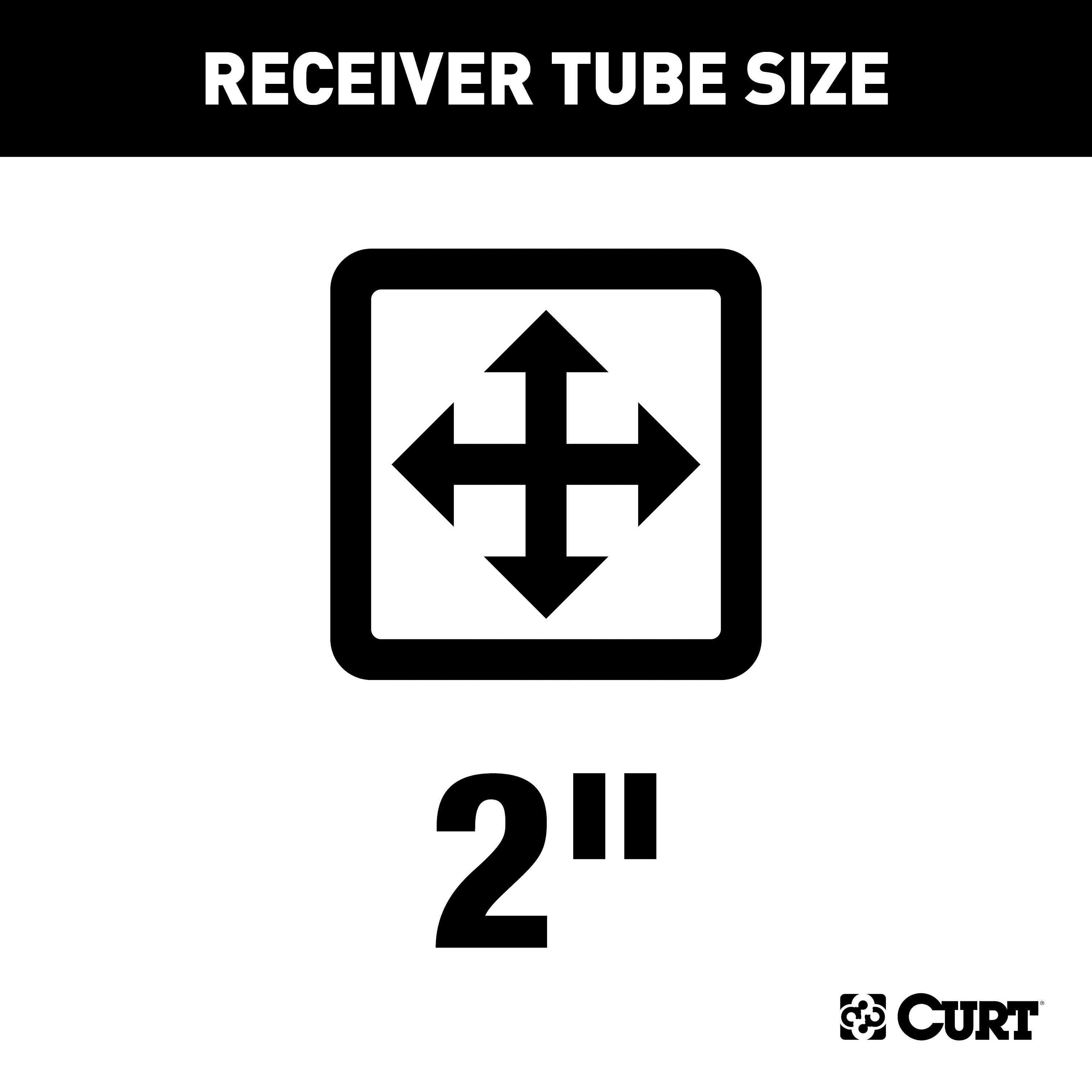
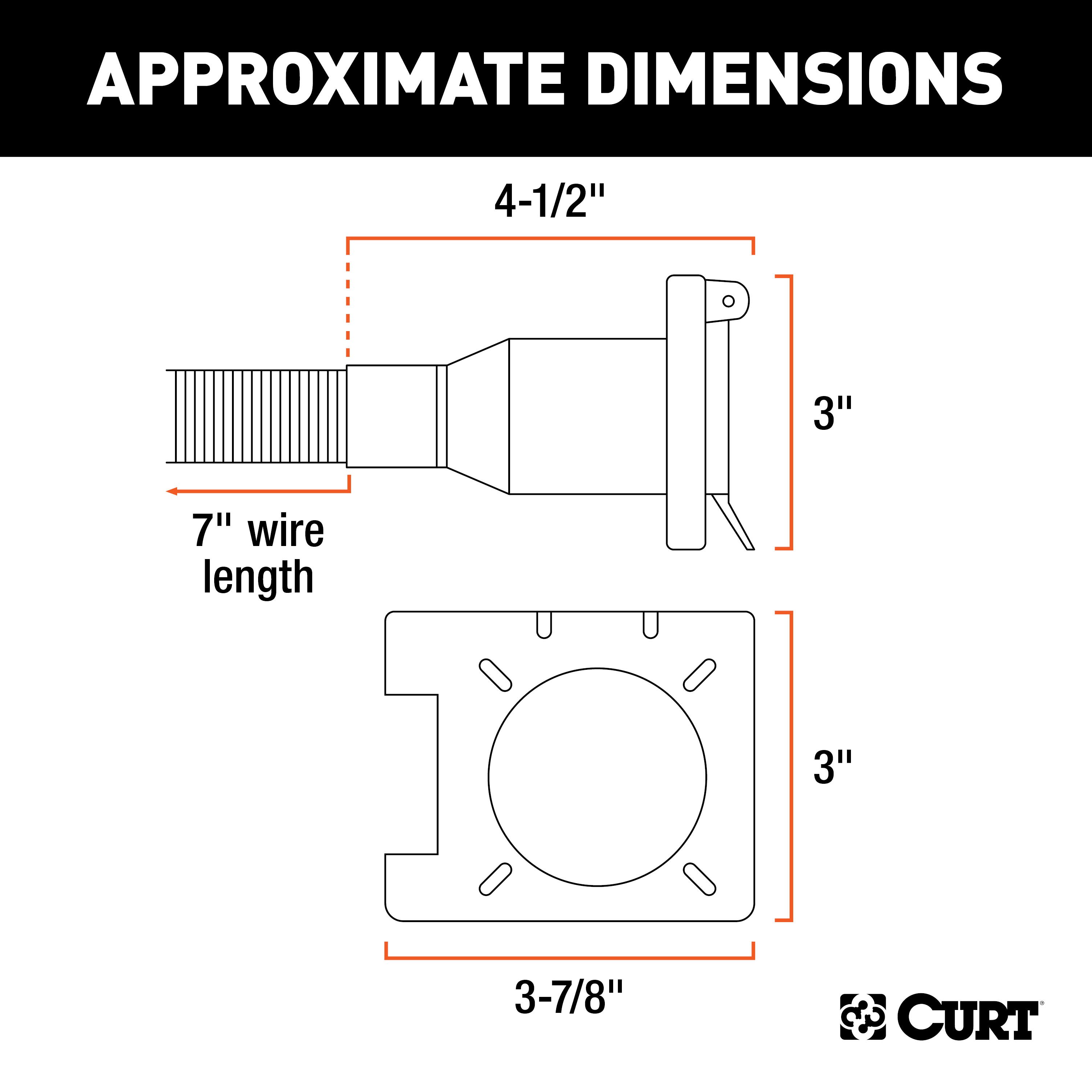
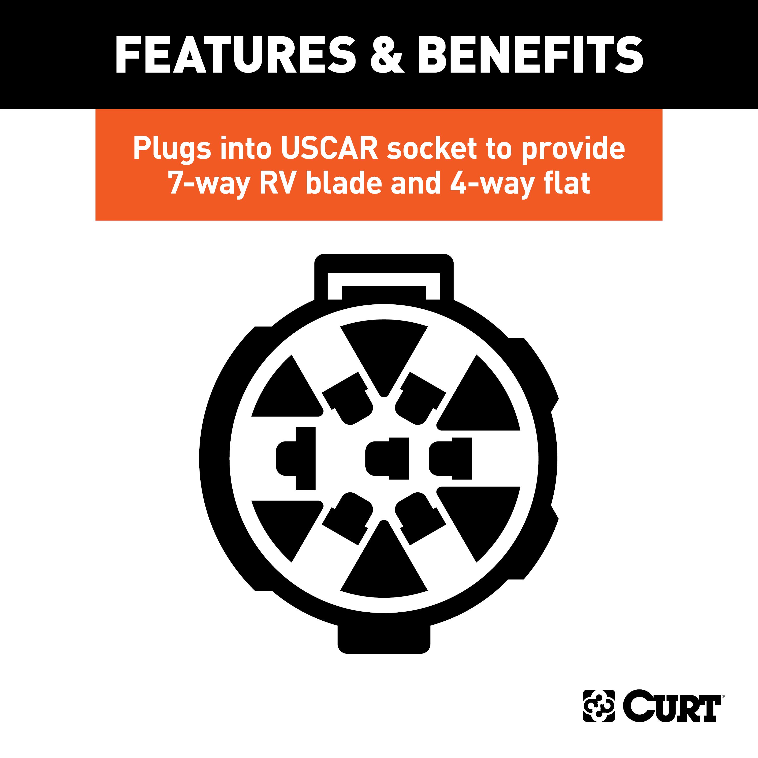
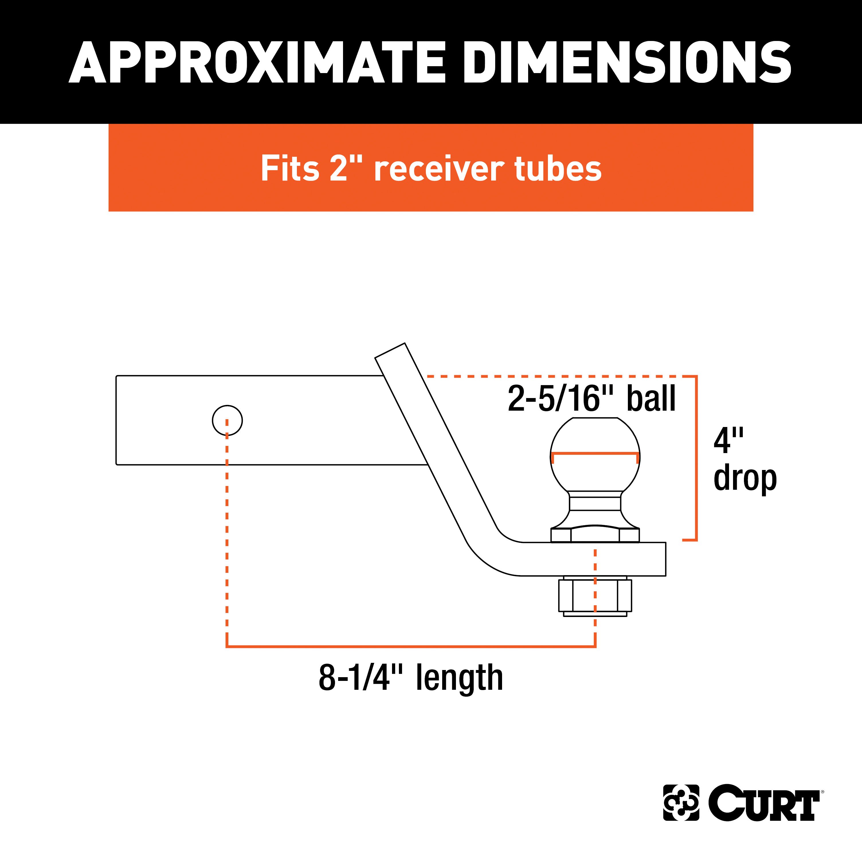
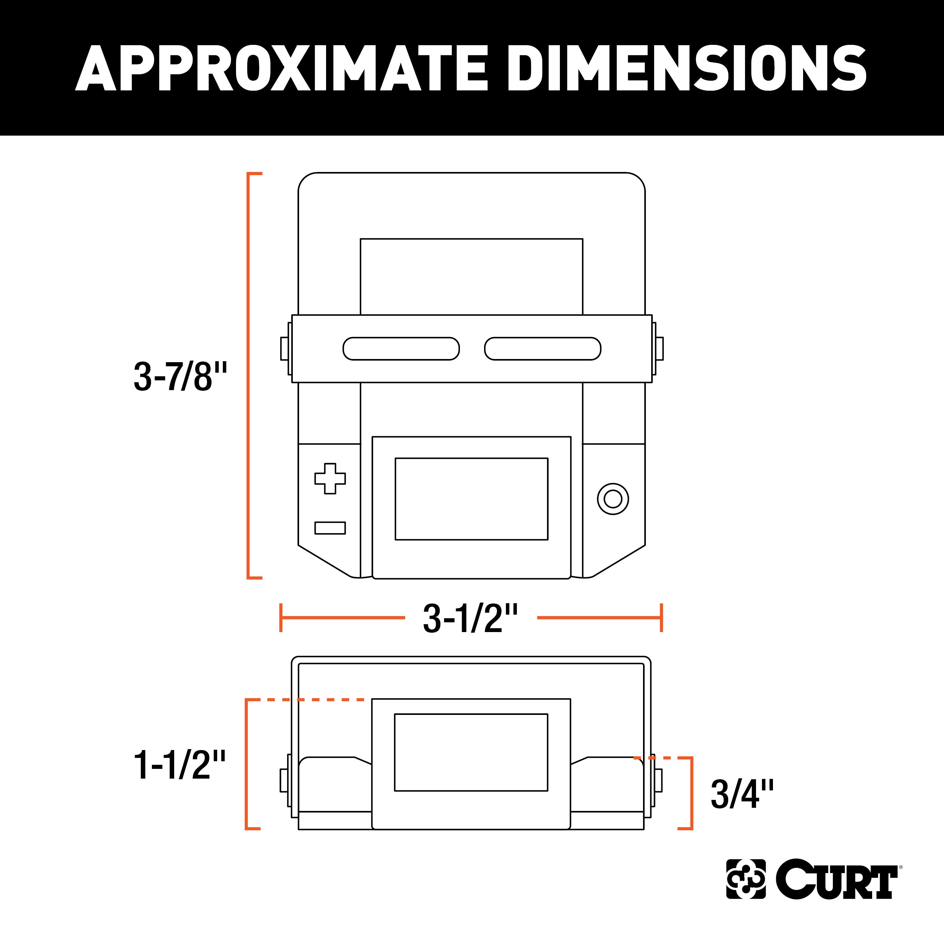
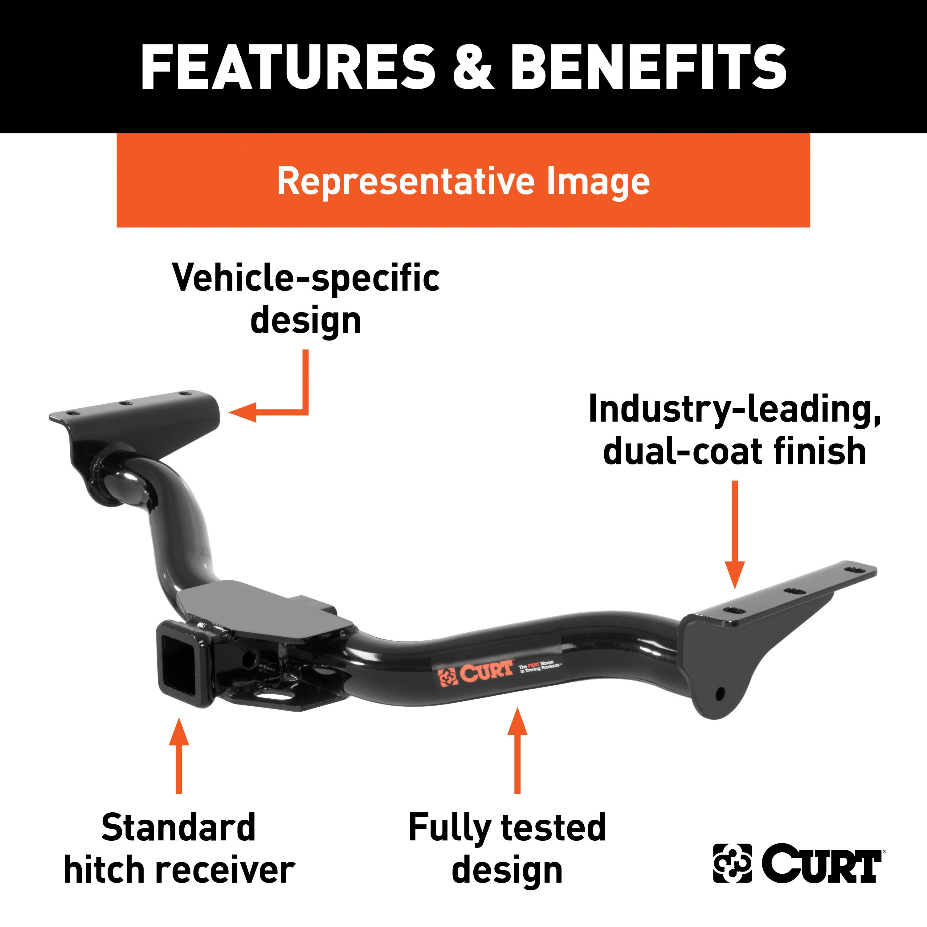
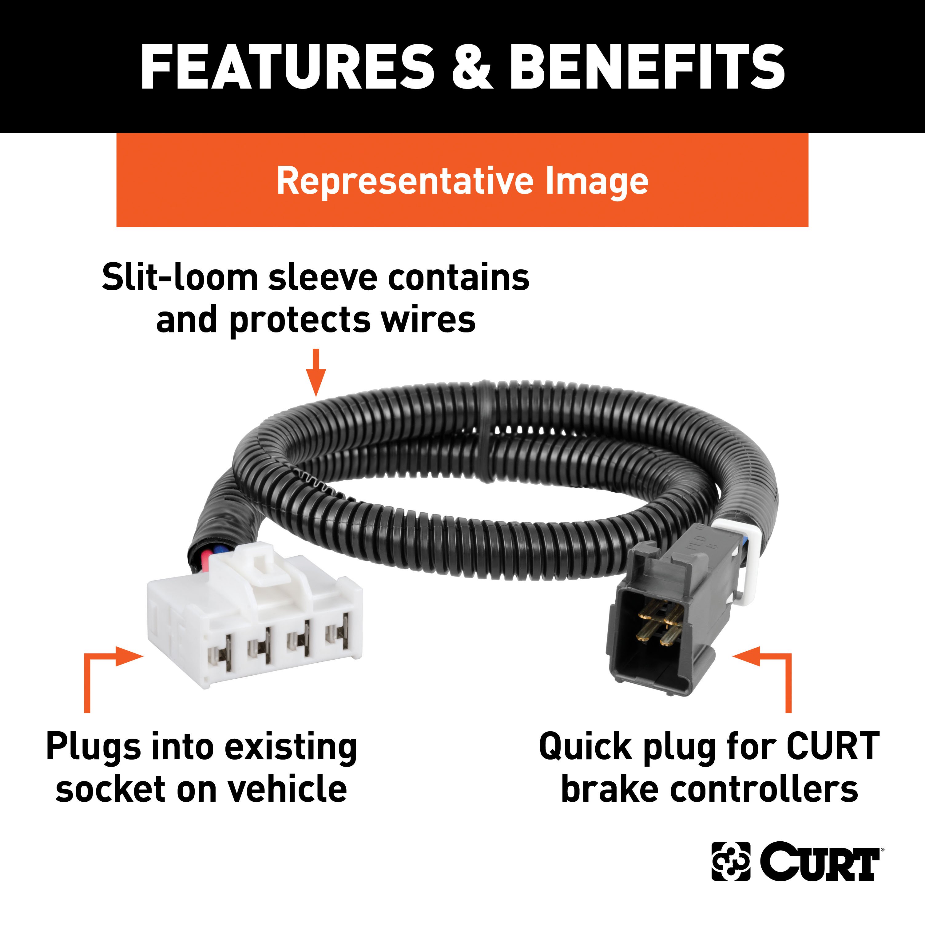
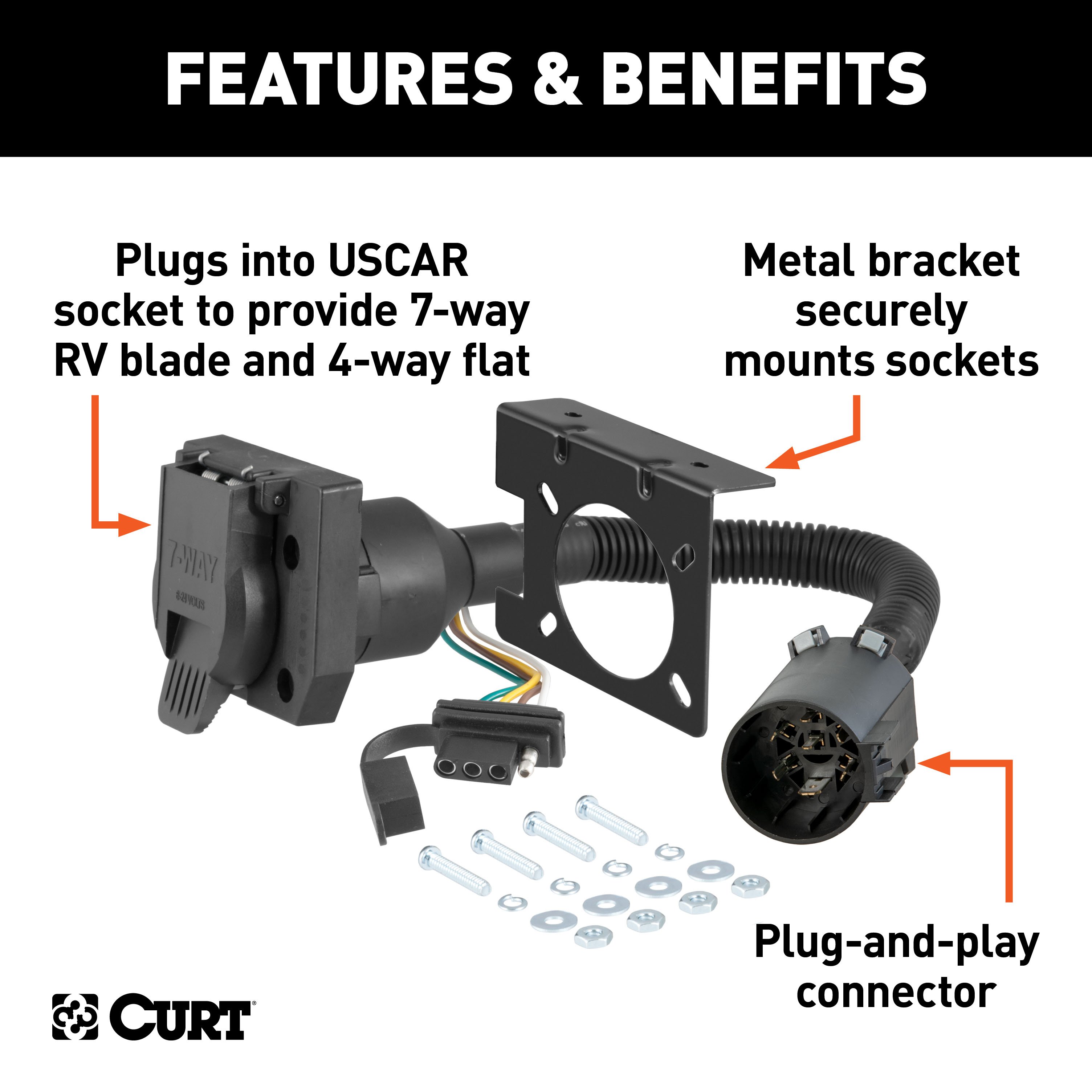
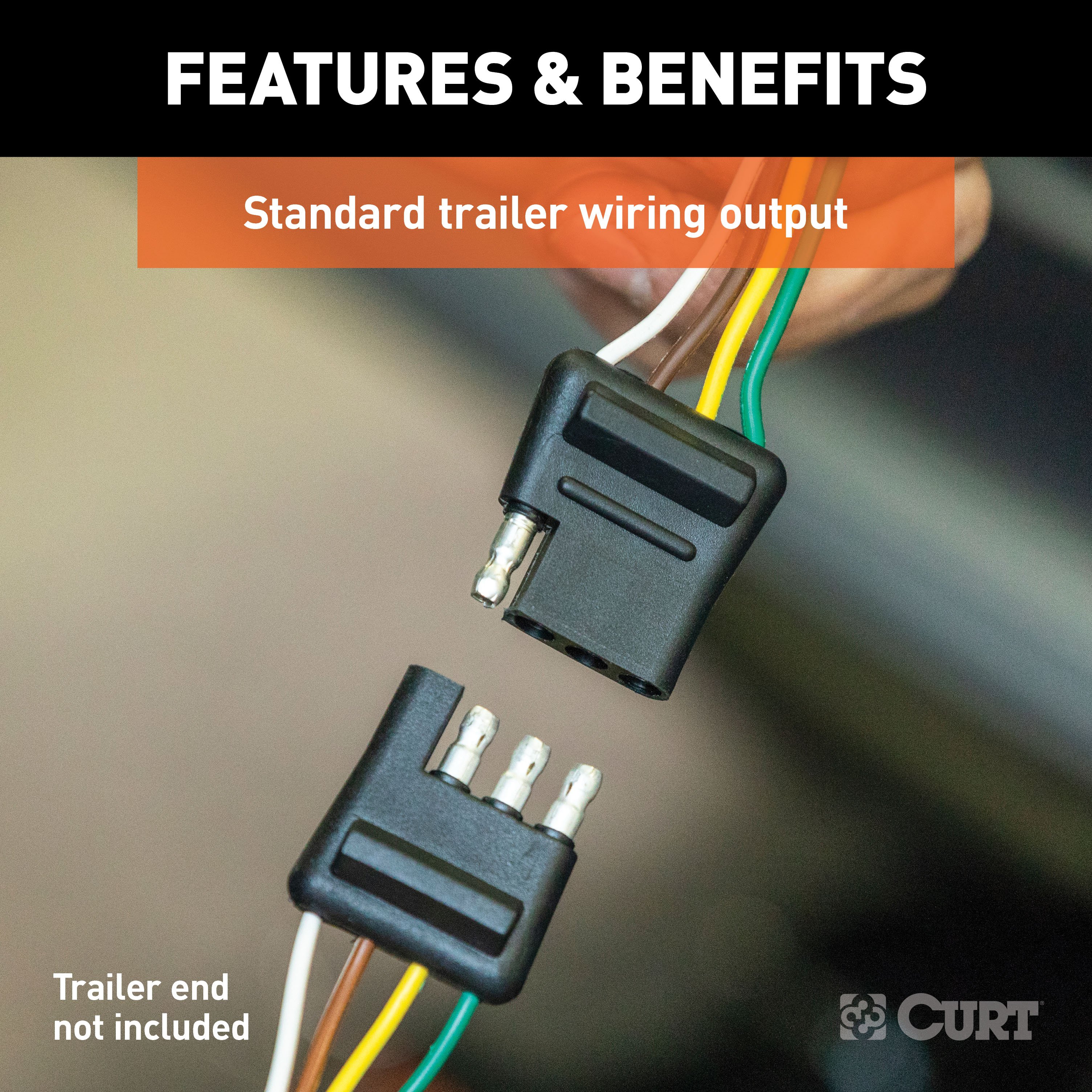
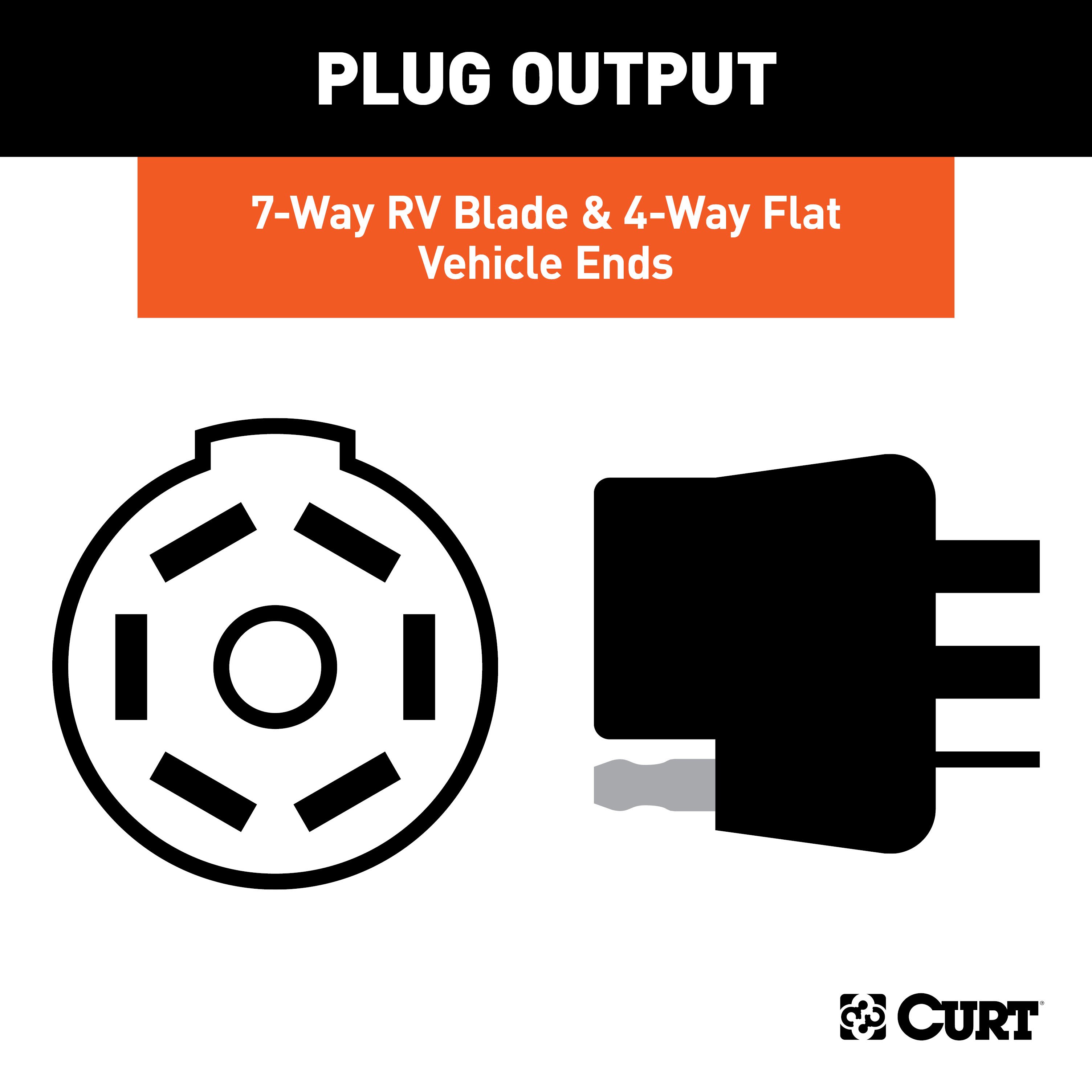
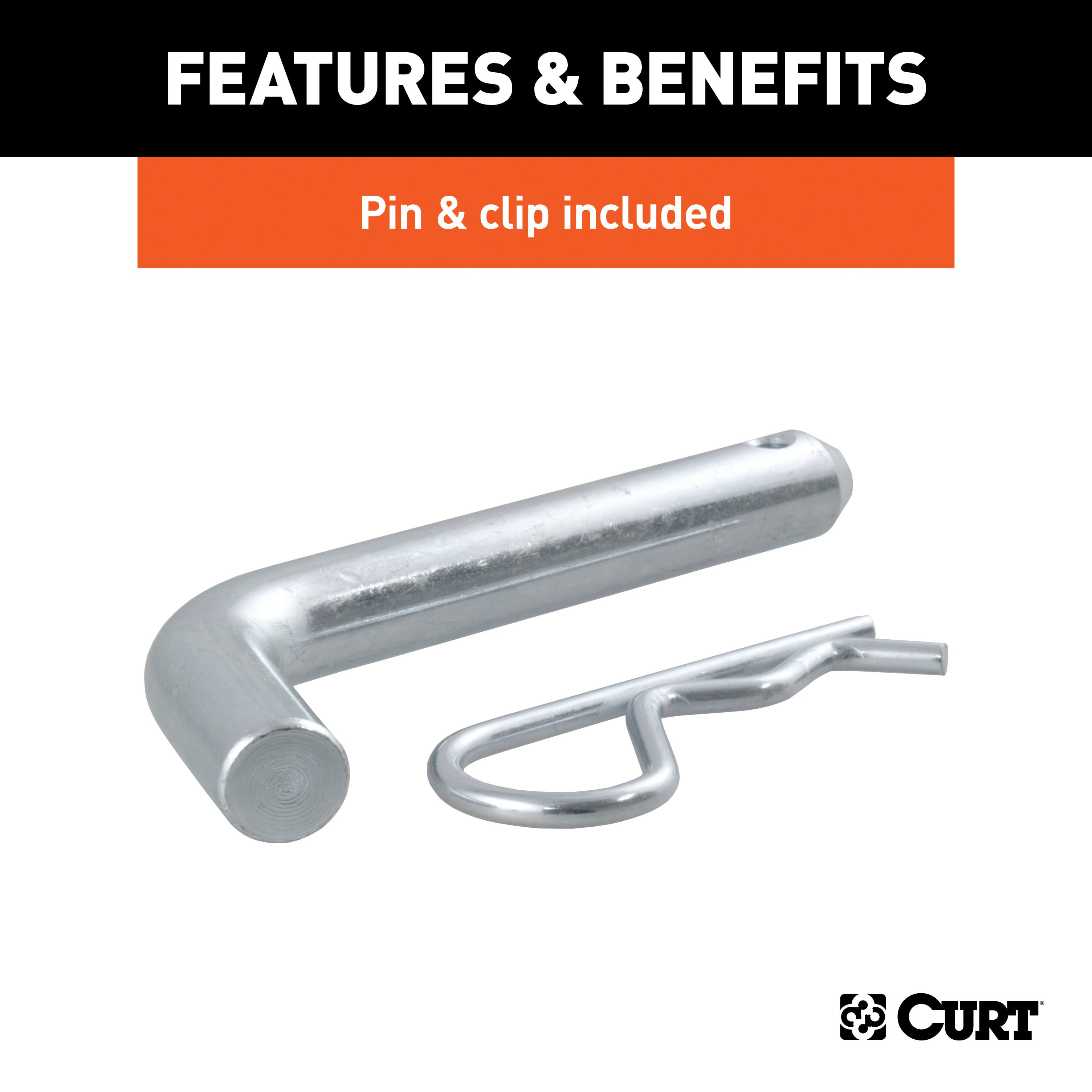
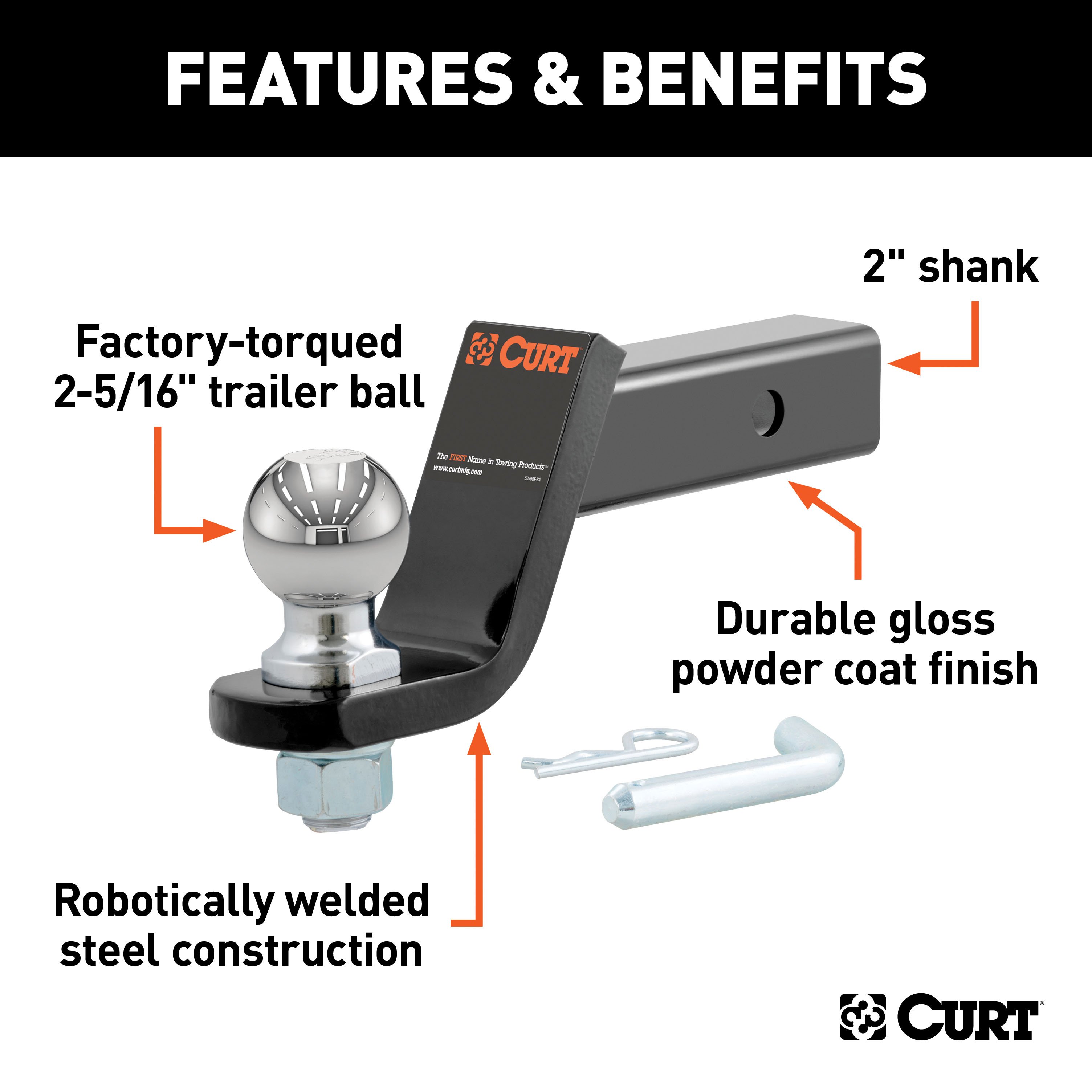
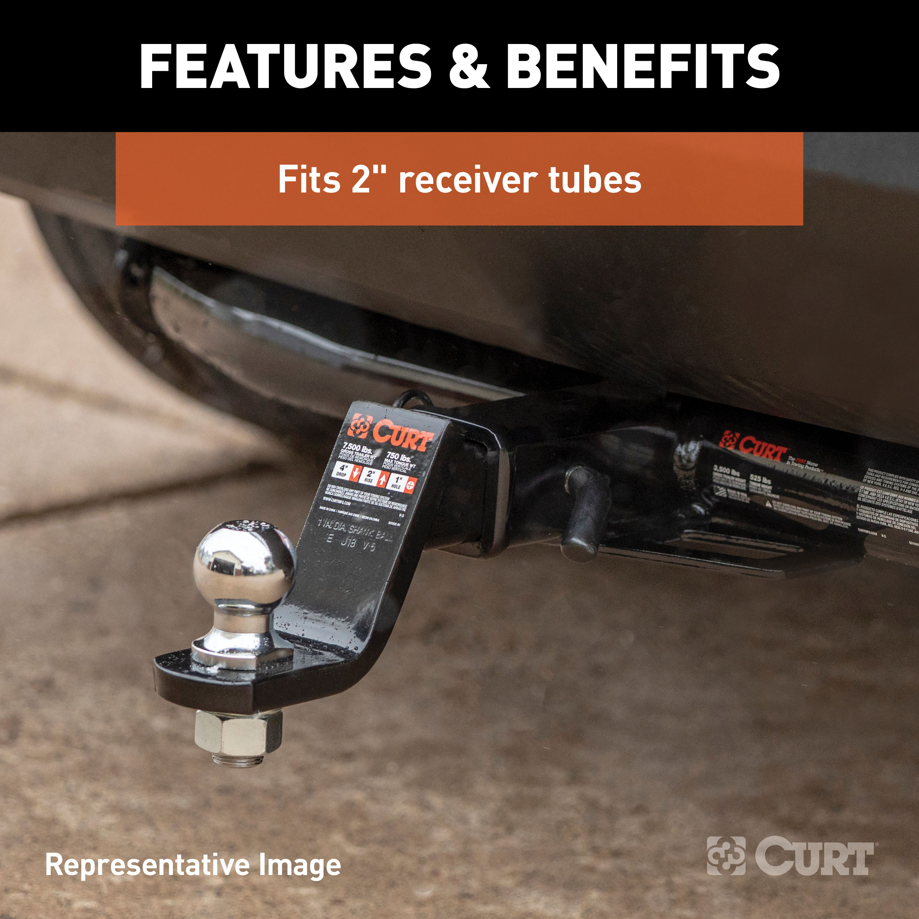
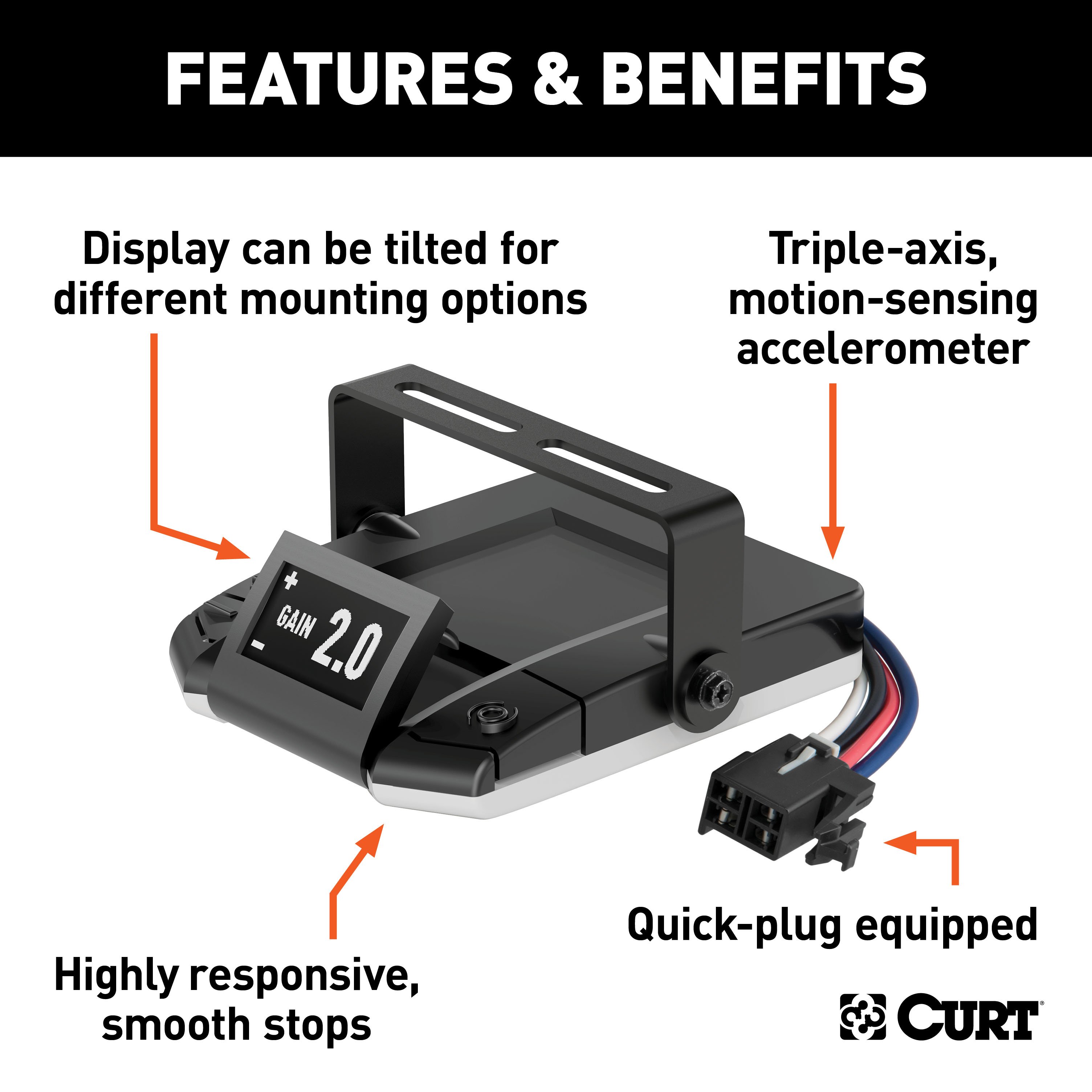
- Includes: Class 3 Trailer Tow Hitch, Dual-Output 7 & 4-Way Connector Plugs into USCAR, Trailer Brake Controller Harness, Loaded Ball Mount with 2-5/16" Ball 2" Shank, Assure Proportional Trailer Brake Controller with Dynamic Screen
Compatibility Chart
Description
Get Expert Help
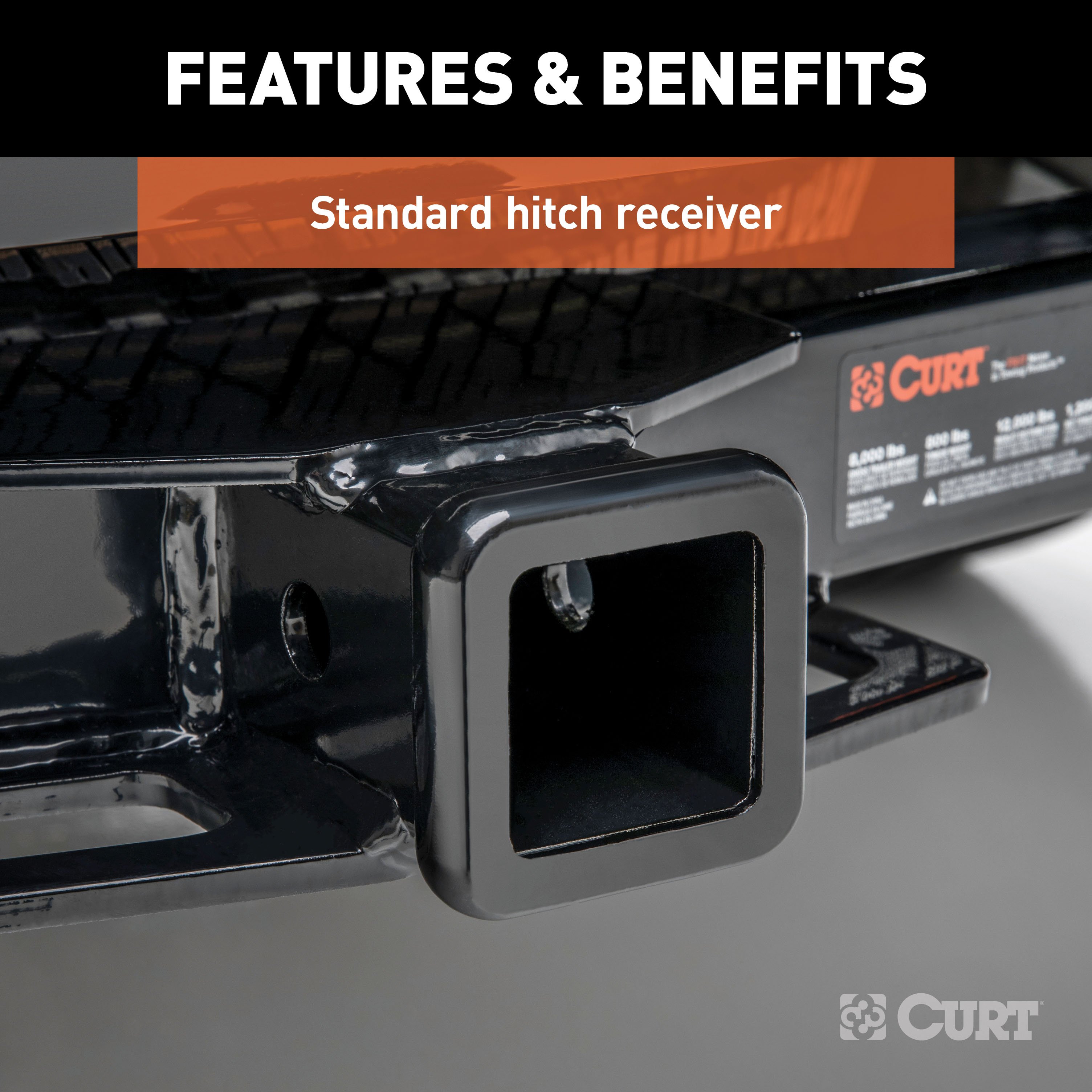
For 2017-2024 Nissan TITAN Tow Package Camp n' Field Trailer Hitch + Brake Controller Curt Assure 51160 Proportional Up To 4 Axles + 7 Way Trailer Wiring Plug & 2-5/16" ball 4 inch drop Fits Models w/ Existing USCAR 7-way Curt 13304 2 inch Tow Re Install Notes
Installation Instructions for Nissan Titan (2017-Present)
Part Numbers:
- 13304
Tools Required:
- Ratchet
- Torque Wrench
- 17mm Socket
- 19mm Socket
- Safety Glasses
Step-by-Step Instructions:
Step 1: Remove Tow Hooks (If Equipped)
- If tow hooks are present, remove them from the vehicle and return the hooks and hardware to the vehicle owner.
Step 2: Position and Secure the Hitch
- Raise the hitch into position, aligning it with the existing weld nuts on the frame rails.
- Thread (10) M12 x 40mm bolts with conical washers into the existing weld nuts, ensuring all fasteners are properly aligned.
Step 3: Torque Fasteners
- Use a torque wrench to tighten all 12mm fasteners to 86 ft-lbs.
Installation Complete
Hardware List:
- (10) M12 x 1.25 x 40mm Hex Head Cap Screws
- (10) 1/2" Conical Washers
Warnings and Safety Information:
- WARNING: Never exceed the vehicle manufacturer's recommended towing capacity.
- Periodically inspect the hitch to ensure all fasteners remain tight and all structural components are sound.
- This product complies with safety specifications and requirements for connecting devices and towing systems under VESC Regulation V-5 and SAE J684.
Specifications:
- Weight Carrying Capacity: 8,000 lbs Trailer Weight, 800 lbs Tongue Weight
- Weight Distribution Capacity: 12,000 lbs Trailer Weight, 1,200 lbs Tongue Weight
Need Assistance? Contact CURT Technical Support at 1-877-287-8634.
Installation Instructions for Nissan Titan (2017-Present)
Part Numbers:
- 13304
Tools Required:
- Ratchet
- Torque Wrench
- 17mm Socket
- 19mm Socket
- Safety Glasses
Step-by-Step Instructions:
Step 1: Remove Tow Hooks (If Equipped)
- If tow hooks are present, remove them from the vehicle and return the hooks and hardware to the vehicle owner.
Step 2: Position and Secure the Hitch
- Raise the hitch into position, aligning it with the existing weld nuts on the frame rails.
- Thread (10) M12 x 40mm bolts with conical washers into the existing weld nuts, ensuring all fasteners are properly aligned.
Step 3: Torque Fasteners
- Use a torque wrench to tighten all 12mm fasteners to 86 ft-lbs.
Installation Complete
Hardware List:
- (10) M12 x 1.25 x 40mm Hex Head Cap Screws
- (10) 1/2" Conical Washers
Warnings and Safety Information:
- WARNING: Never exceed the vehicle manufacturer's recommended towing capacity.
- Periodically inspect the hitch to ensure all fasteners remain tight and all structural components are sound.
- This product complies with safety specifications and requirements for connecting devices and towing systems under VESC Regulation V-5 and SAE J684.
Specifications:
- Weight Carrying Capacity: 8,000 lbs Trailer Weight, 800 lbs Tongue Weight
- Weight Distribution Capacity: 12,000 lbs Trailer Weight, 1,200 lbs Tongue Weight
Attention: This is a summary of the installation procedure. For complete installation instructions, including diagrams and detailed information from the manufacturer, please download the full installation PDF.
For Technical Support:
For technical support and assistance, our team of experts is available to help. You can reach our tech support by visiting www.trailerjacks.com or calling 877-869-6690.
Warranty Information:
Warranty covers defects in material and workmanship for the duration specified by the manufacturer. For complete warranty instructions, please download the full installation PDF.
Installation Instructions for T-Connector Adapter ## Part Number: - 55774 ## Applications: This adapter is compatible with the following vehicles: - Buick: Enclave, Rainier - Cadillac: Escalade - Chevrolet: Avalanche, Silverado, Tahoe, Suburban, Trailblazer - GMC: Sierra, Yukon, Acadia, Envoy - Hummer: H2, H3 - Infiniti: QX56 - Isuzu: Ascender - Nissan: Titan, Pathfinder - Oldsmobile: Bravada - Saab: 9-7X - Saturn: Outlook ## Warnings: - Verify that there are no hidden items behind or under any surface before drilling to avoid damage or personal injury. ## Step-by-Step Instructions: ### For Vehicles Without a Factory 7-Way: 1. Locate the Trailer Harness Connector: - The harness is located under the vehicle, behind the bumper on the driver’s side. 2. Remove the Protective Cap: - Save the cap and ensure the mating surfaces of the connectors are free of dirt. Clean if necessary. 3. Connect the T-Connector Adapter: - Insert the T-connector into the vehicle's connector. Ensure it is fully inserted and the locking tabs are in place. 4. Attach the Protective Cap: - Place the protective cap on the remaining plug end. 5. Skip to Step 7 to complete the installation. ### For Vehicles With a Factory 7-Way: 5. Locate the Factory 7-Way Socket: - The socket is attached to the hitch on the driver’s side. 6. Separate the Factory Socket: - Disconnect the factory socket and the 7-way. 7. Connect the T-Connector: - Insert the T-connector between the factory socket and the 7-way. Ensure all connectors are fully inserted and the locking tabs are secure. ## Final Notes: - Ensure all connections are secure and test the functionality of the wiring. - For additional information, refer to the vehicle owner's manual. For further assistance, contact your manufacturer or authorized dealer.
Installation Instructions for T-Connector Adapter
Part Number:
- 55774
Applications:
This adapter is compatible with the following vehicles:
- Buick: Enclave, Rainier
- Cadillac: Escalade
- Chevrolet: Avalanche, Silverado, Tahoe, Suburban, Trailblazer
- GMC: Sierra, Yukon, Acadia, Envoy
- Hummer: H2, H3
- Infiniti: QX56
- Isuzu: Ascender
- Nissan: Titan, Pathfinder
- Oldsmobile: Bravada
- Saab: 9-7X
- Saturn: Outlook
Warnings:
- Verify that there are no hidden items behind or under any surface before drilling to avoid damage or personal injury.
Step-by-Step Instructions:
For Vehicles Without a Factory 7-Way:
-
Locate the Trailer Harness Connector:
- The harness is located under the vehicle, behind the bumper on the driver’s side.
-
Remove the Protective Cap:
- Save the cap and ensure the mating surfaces of the connectors are free of dirt. Clean if necessary.
-
Connect the T-Connector Adapter:
- Insert the T-connector into the vehicle's connector. Ensure it is fully inserted and the locking tabs are in place.
-
Attach the Protective Cap:
- Place the protective cap on the remaining plug end.
-
Skip to Step 7 to complete the installation.
For Vehicles With a Factory 7-Way:
-
Locate the Factory 7-Way Socket:
- The socket is attached to the hitch on the driver’s side.
-
Separate the Factory Socket:
- Disconnect the factory socket and the 7-way.
-
Connect the T-Connector:
- Insert the T-connector between the factory socket and the 7-way. Ensure all connectors are fully inserted and the locking tabs are secure.
Final Notes:
- Ensure all connections are secure and test the functionality of the wiring.
- For additional information, refer to the vehicle owner's manual. For further assistance, contact your manufacturer or authorized dealer.
Installation Notes:
- Attention: This is a summary of the installation procedure. For complete installation instructions, including diagrams and detailed information from the manufacturer, please download the full installation PDF.
Technical Support:
- For technical support and assistance, our team of experts is available to help. You can reach our tech support by visiting www.trailerjacks.com or calling 877-869-6690.
Installation Instructions for Infiniti and Nissan Vehicles
Part Numbers:
- 51382
- 51383
Wiring Access Location:
- BH1 - Under dash, left of steering column, near emergency brake pedal
Step-by-Step Instructions:
Step 1: Locate the vehicle brake control harness connector
- Find the 6-pin vehicle brake control harness connector under the dash, to the left of the steering column.
- It will be taped to another harness near the emergency brake pedal and will resemble the CURT brake control harness.
Step 2: Connect the CURT harness to the vehicle connector
- Insert the CURT brake control harness connector into the vehicle connector.
- Ensure the connector is fully inserted and the locking tabs are secure.
Step 3: Connect to the brake control unit
- Attach the brake control harness's black connector to the brake control's quick plug connector.
- Secure the harness using the provided cable ties, avoiding pinch points.
Step 4: Mount and test the brake control unit
- Complete the installation using the brake control instructions.
- Mount the unit as directed and perform the recommended test procedures to verify functionality.
Hardware List:
- (1) CURT brake control harness
- (2) Cable ties
Safety Notes:
- For vehicles not equipped with an OEM trailer tow package, fuses and relays may be required to complete output and battery feed circuits (sold separately).
- Consult the owner's manual for specific fuse and relay locations.
Specifications:
- Compatible Vehicles:
- Infiniti QX56
- Nissan Armada
- Nissan Frontier
- Nissan Pathfinder
- Nissan Pathfinder Armada
- Nissan Titan
- Nissan Titan XD
- Nissan Xterra
Installation Instructions for Vehicles with BH1 Wiring Location
Part Numbers:
- 51382
- 51383
Wiring Access Location:
- BH1 - Under dash, left of steering column, near emergency brake pedal
Step-by-Step Instructions:
Step 1: Locate the vehicle brake control harness connector
- Find the 6-pin vehicle brake control harness connector under the dash, to the left of the steering column.
- It will be taped to another harness near the emergency brake pedal and will resemble the brake control harness.
Step 2: Connect the brake control harness to the vehicle connector
- Insert the brake control harness connector into the vehicle connector.
- Ensure the connector is fully inserted and the locking tabs are secure.
Step 3: Connect to the brake control unit
- Attach the brake control harness's black connector to the brake control's quick plug connector.
- Secure the harness using the provided cable ties, avoiding pinch points.
Step 4: Mount and test the brake control unit
- Complete the installation using the brake control instructions.
- Mount the unit as directed and perform the recommended test procedures to verify functionality.
Hardware List:
- (1) Brake control harness
- (2) Cable ties
Safety Notes:
- For vehicles not equipped with an OEM trailer tow package, fuses and relays may be required to complete output and battery feed circuits (sold separately).
- Consult the owner's manual for specific fuse and relay locations.
Specifications:
- Compatible Vehicles:
- Vehicles with BH1 wiring location
For complete installation instructions, including diagrams and detailed information from the manufacturer, please download the full installation PDF.
For technical support and assistance, our team of experts is available to help. You can reach our tech support by visiting www.trailerjacks.com or calling 877-869-6690.
Installation Instructions for Brake Controller
Product Information:
- Application: For trailers with 2 to 8 brakes
- System: 12-volt negative ground systems
Package Contents:
- (1) Brake Controller Module with Quick Plug
- (1) Mounting Bracket
- (2) Keyed Spacers
- (4) Mounting Bracket Screws
- (1) Quick Reference Card
- (2) Keyed Washers
Tools Required:
- Drill with 1/8" drill bit
- Wire Crimpers
- Wire Cutters
- Phillips Head Screwdriver
Key Features:
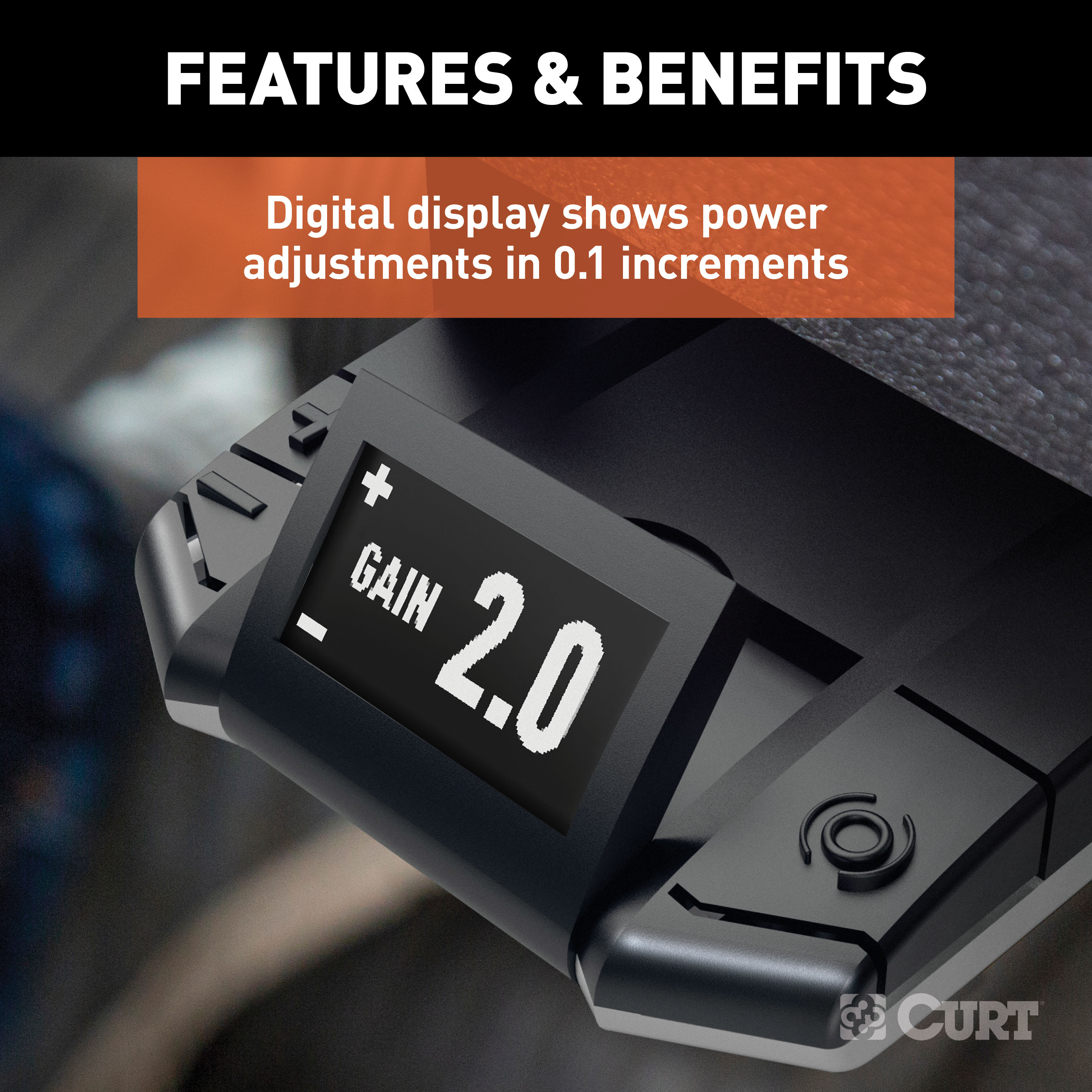
- Display for output and sensitivity settings
- Manual trailer braking control
- Switchable manual control options (100% or output setting)
- Brake light activation switch
- Reverse voltage and overload protection
- Compatible with electric and hydraulic trailer brake systems
Warnings and Important Notes:
- The brake controller’s positive and ground wires must connect directly to the vehicle’s battery with 10-gauge stranded wire.
- Avoid mounting near a CB radio or other RF transmitters.
- Disconnect the trailer plug when testing a breakaway switch.
Step-by-Step Installation Instructions:
1. Select the Mounting Location:
- The mounting location should be:
- Within the driver’s reach
- On a solid surface
- Free of obstructions behind the mounting surface
2. Install the Mounting Bracket:
- Position the bracket and mark the mounting holes.
- Drill holes using a 1/8” drill bit.
- Secure the bracket with the provided self-tapping screws (do not overtighten).
3. Attach the Brake Controller:
- Place the keyed spacer and washer on each side of the mounting bracket.
- Slide the brake controller into the bracket and secure it with screws.
4. Wiring the Brake Controller:
- Black Wire (Power Input): Connect to the positive (+) battery terminal through a 30-amp auto-reset circuit breaker.
- White Wire (Ground): Connect directly to the negative (-) battery terminal.
- Red Wire (Stoplight Input): Connect to the stoplight wire that is “hot” only when the brake pedal is pressed.
- Use a test probe to verify the correct wire.
- Blue Wire (Brake Output): Connect to the trailer’s brake control wire through the 7-way connector.
Switch Settings (Manual Control Configuration):
-
Brake Light Activation Switch:
- ON: Activates brake lights when the manual control is used (default).
- OFF: Brake lights remain inactive during manual braking.
-
Manual Brake Output Switch:
- ON: Limits manual braking to the gain (output) setting.
- OFF: Allows 100% braking power regardless of the output setting.
Setup and Calibration:
-
Connect the Trailer:
- Plug the trailer connector into the vehicle’s 7-way outlet.
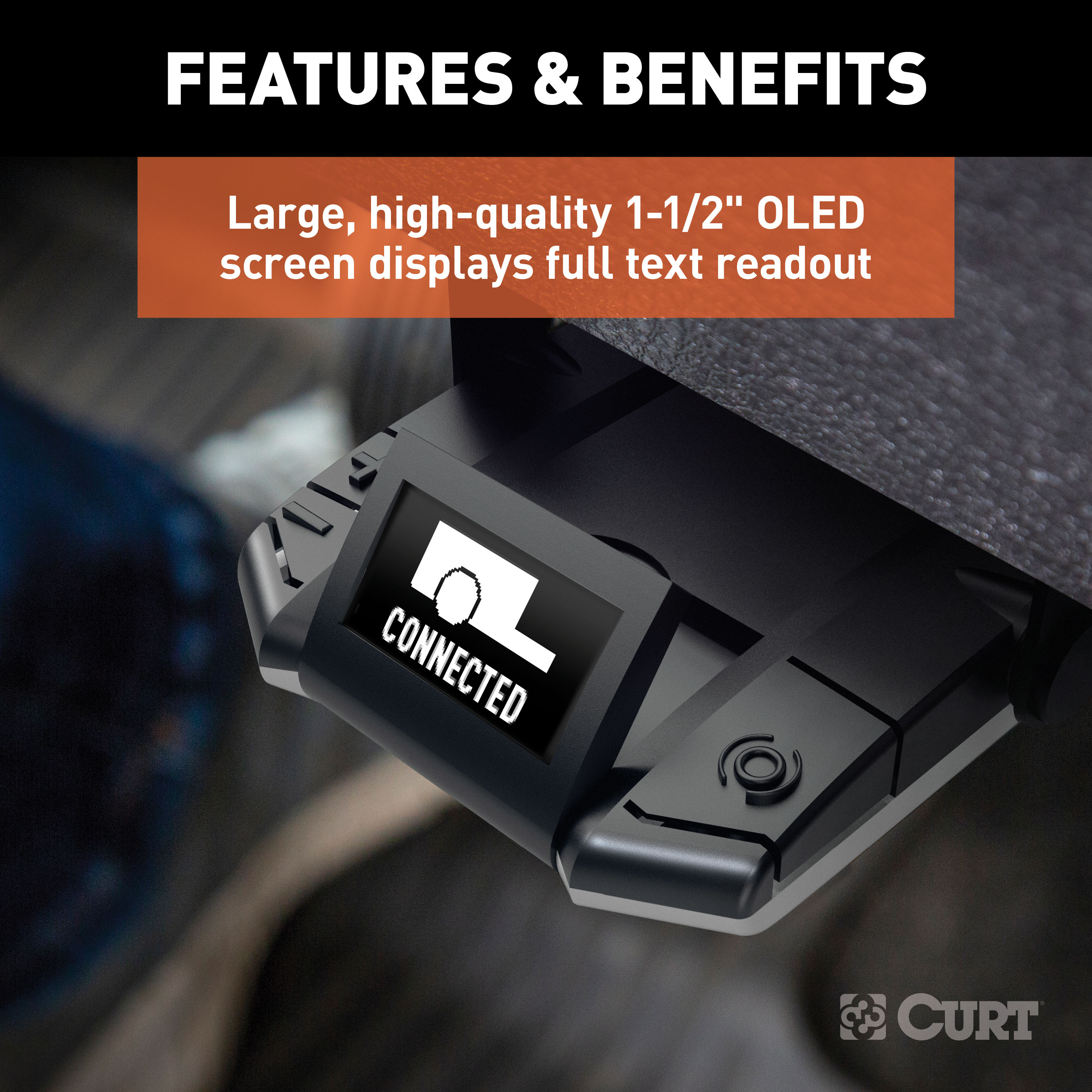
- The controller will calibrate automatically, displaying "Calibration" followed by "Connected."
-
Set Initial Output and Sensitivity:
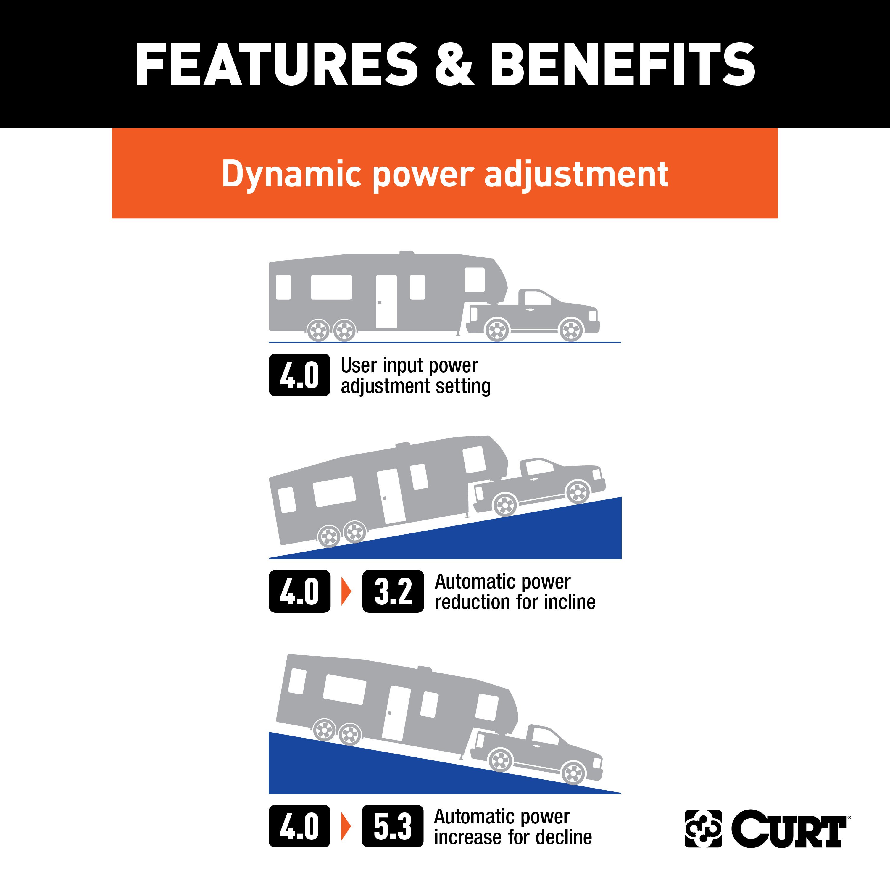
- Set the output to 2.0 and sensitivity (load) to 1.0 using the (+) and (-) buttons.
-
Test Drive and Adjust:
- Drive on a level surface at 25 mph.
- Press the brake pedal:
- Increase Output: If trailer braking feels insufficient.
- Decrease Output: If trailer brakes lock up.
- Adjust sensitivity for smoother stops using the (+) and (-) buttons.
Display Indicators:
| Indicator | Description |
|---|---|
| Connected | Trailer connected, standby mode |
| Not Connected | No trailer detected |
| Low Volt | Tow vehicle system voltage is low |
| Overload | Trailer brake system fault detected |
| Short | Stoplight wire shorted to ground |
| Error | Accelerometer error |
| Disconnect | Trailer disconnected |
Troubleshooting Guide:
- Display is Blank: Check power and ground connections.
- Display Shows "Low Volt": Verify vehicle’s battery and charging system.
- "Overload" Error: Inspect the blue wire and trailer brake circuit for shorts.
- No Trailer Brakes: Confirm proper wiring of the trailer connector.
Final Notes:
- Secure all loose wires with cable ties.
- Periodically test the system for proper operation.
- Avoid exceeding the towing vehicle's maximum electrical capacity.
Attention: This is a summary of the installation procedure. For complete installation instructions, including diagrams and detailed information, download the full installation PDF.
For Technical Support: Our team of experts is available to help. You can reach tech support by visiting www.trailerjacks.com or calling 877-869-6690.


