


Trailer Tow Hitch For 19-26 Volvo XC40 19-24 XC40 Recharge 22-24 C40 Recharge 25-26 EX40 Basket Cargo Carrier Platform w/ Hitch Pin
Model: 76245 63153 63240Custom Fit Trailer Hitch w/ Pin & Clip
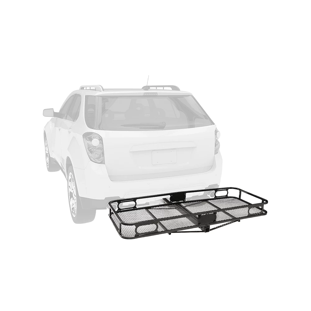
Cargo Hitch Basket
Installation Hardware
Installation Instructions
Fits The Following Vehicles
2019 - 2023 Volvo, XC40, All Styles
Trailer Hitch Specs:
| Part Number | 76245 |
| Brand | Draw-Tite |
| Finish | Black Powdercoat |
| Class | 3/4 |
| Receiver size opening | 2" |
| Max gross trailer weight | 4,000 lbs |
| Max GTW w/ weight distribution | N/A |
| Max Tongue Weight | 600 lbs |
| Warranty | Lifetime |
| Installation Instructions |
When your gear is essential, these hitch baskets help you pack it in.
- 5.5" side rails to retain cargo
- Fits 2" trailer hitch receives
- 2-1/2"" Shank Rise elevates the platform
- 12-3/4" Distance from hitch pin to the edge of carrier
- Mesh floor for easy cleanup
- Up to 500 lbs. capacity
- Up to 60" x 24" (inside dimensions) cargo platform
- Black powder coat finish resists corrosion
- Bikes clips and fully functional light systems available
- 1 Year Warranty
Questions or Comments? Call 702-374-8999
Thank you for choosing Draw Tite the most powerful name in towing industry bar none. Manufactured by the same people that brought you Reese and Hidden Hitch all of our products come with standard lifetime warranty and support. Our custom hitches mount easily on your Car Truck Van SUV and RV. Most applications simply bolt on without any need for drilling or modifying your bumper. Please review installation instructions manual pdf file above for exact step by step instructions. Chose Class 1 or 2 for light duty towing, chose Class 3 4 and 5 for heavy duty towing. Pair your hitch with accessories like a ball mount that is available in several drop and rise configurations. Choose a 2 inch ball to haul most standard trailers. Choose a 1-7/8" ball to tow small and u tility trailers. Our hitches come with generous tongue weight ratings for use with cargo racks and other accessories. All parts in our store are sold at a discount.
$505 99 $777.83 35% OFF
- Best Price on Web Guarantee
- Fastest Shipping
- FREE Shipping
- Pre-Order
We match lower prices from major authorized retailers for brand-new products in original packaging, provided the item is in stock. The competing seller must be an authorized, professional retail business; offers from
individuals, auctions, peer-to-peer sites, or unauthorized sellers don’t qualify. Used, refurbished, or open-box items are excluded.
Please see our full terms for details.
Verify Fitment
$777.83 $505 99
Questions? Call our Auto Experts at (877) 869-6690
Get it now, pay later
Select installments at checkout to split your purchase into 4 interest-free payments of $ every 2 weeks.
- No fees, ever.
- No impact on your credit score.
Payment options are offered by Affirm and are subject to an eligibility check and might not be available in all states. CA Residents: Loans by Affirm Loan Services, LLC are made or arranged pursuant to a California Finance Lender license.
Installments in partnership with
![]() .
Affirm and its offerings are supported in English only. Translations are not provided by Affirm.
.
Affirm and its offerings are supported in English only. Translations are not provided by Affirm.
Don't Miss the Next Restock!
We are working hard to bring this back. Join our VIP list to get an instant alert the second it is available.
Product Details
- Brand: Draw-Tite
- Model: 76245 63153 63240
- Includes: Class 3 Trailer Tow Hitch, Rambler Hitch Mount Cargo Carrier, Trailer Tow Hitch Pin & Clip
-
Fitment CodesHZNH454 19-26 Volvo XC40 19-24 XC40 Recharge 22-24 C40 Recharge 25-26 EX40
Compatibility Chart
| Year Range | Make | Model | Style | Fitment Code |
|---|
Description
Custom Fit Trailer Hitch w/ Pin & Clip
Cargo Hitch Basket
Installation Hardware
Installation Instructions
Fits The Following Vehicles
2019 - 2023 Volvo, XC40, All Styles
Trailer Hitch Specs:
| Part Number | 76245 |
| Brand | Draw-Tite |
| Finish | Black Powdercoat |
| Class | 3/4 |
| Receiver size opening | 2" |
| Max gross trailer weight | 4,000 lbs |
| Max GTW w/ weight distribution | N/A |
| Max Tongue Weight | 600 lbs |
| Warranty | Lifetime |
| Installation Instructions |
When your gear is essential, these hitch baskets help you pack it in.
- 5.5" side rails to retain cargo
- Fits 2" trailer hitch receives
- 2-1/2"" Shank Rise elevates the platform
- 12-3/4" Distance from hitch pin to the edge of carrier
- Mesh floor for easy cleanup
- Up to 500 lbs. capacity
- Up to 60" x 24" (inside dimensions) cargo platform
- Black powder coat finish resists corrosion
- Bikes clips and fully functional light systems available
- 1 Year Warranty
Questions or Comments? Call 702-374-8999
Thank you for choosing Draw Tite the most powerful name in towing industry bar none. Manufactured by the same people that brought you Reese and Hidden Hitch all of our products come with standard lifetime warranty and support. Our custom hitches mount easily on your Car Truck Van SUV and RV. Most applications simply bolt on without any need for drilling or modifying your bumper. Please review installation instructions manual pdf file above for exact step by step instructions. Chose Class 1 or 2 for light duty towing, chose Class 3 4 and 5 for heavy duty towing. Pair your hitch with accessories like a ball mount that is available in several drop and rise configurations. Choose a 2 inch ball to haul most standard trailers. Choose a 1-7/8" ball to tow small and u tility trailers. Our hitches come with generous tongue weight ratings for use with cargo racks and other accessories. All parts in our store are sold at a discount.