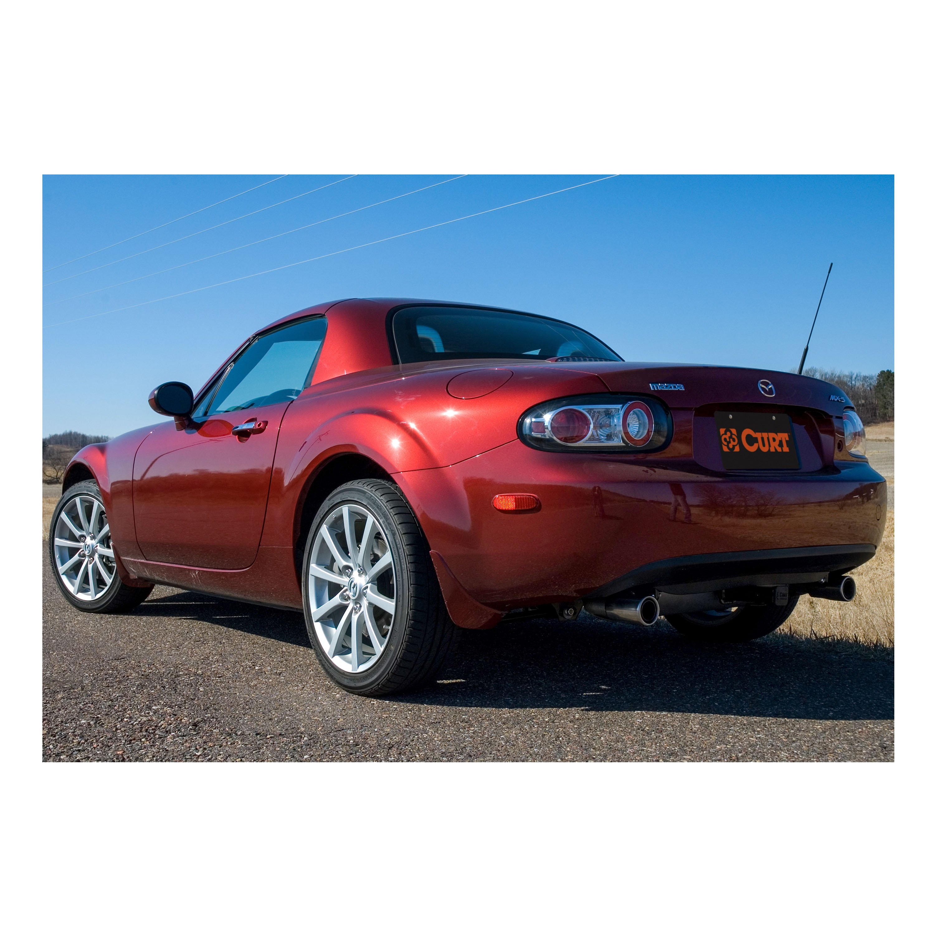
Product Details
- Brand: Curt
- Model: 11028 56082-CH2830
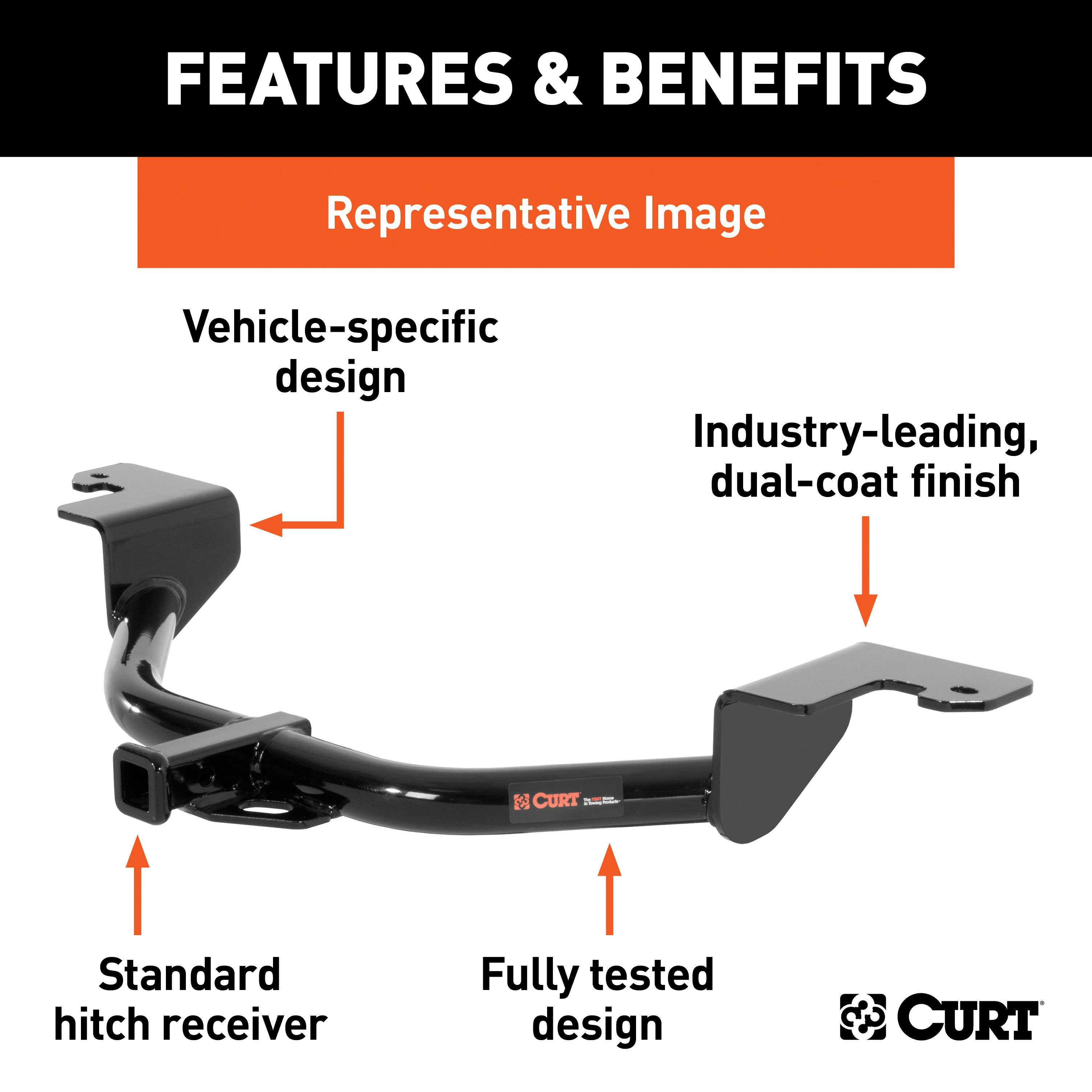
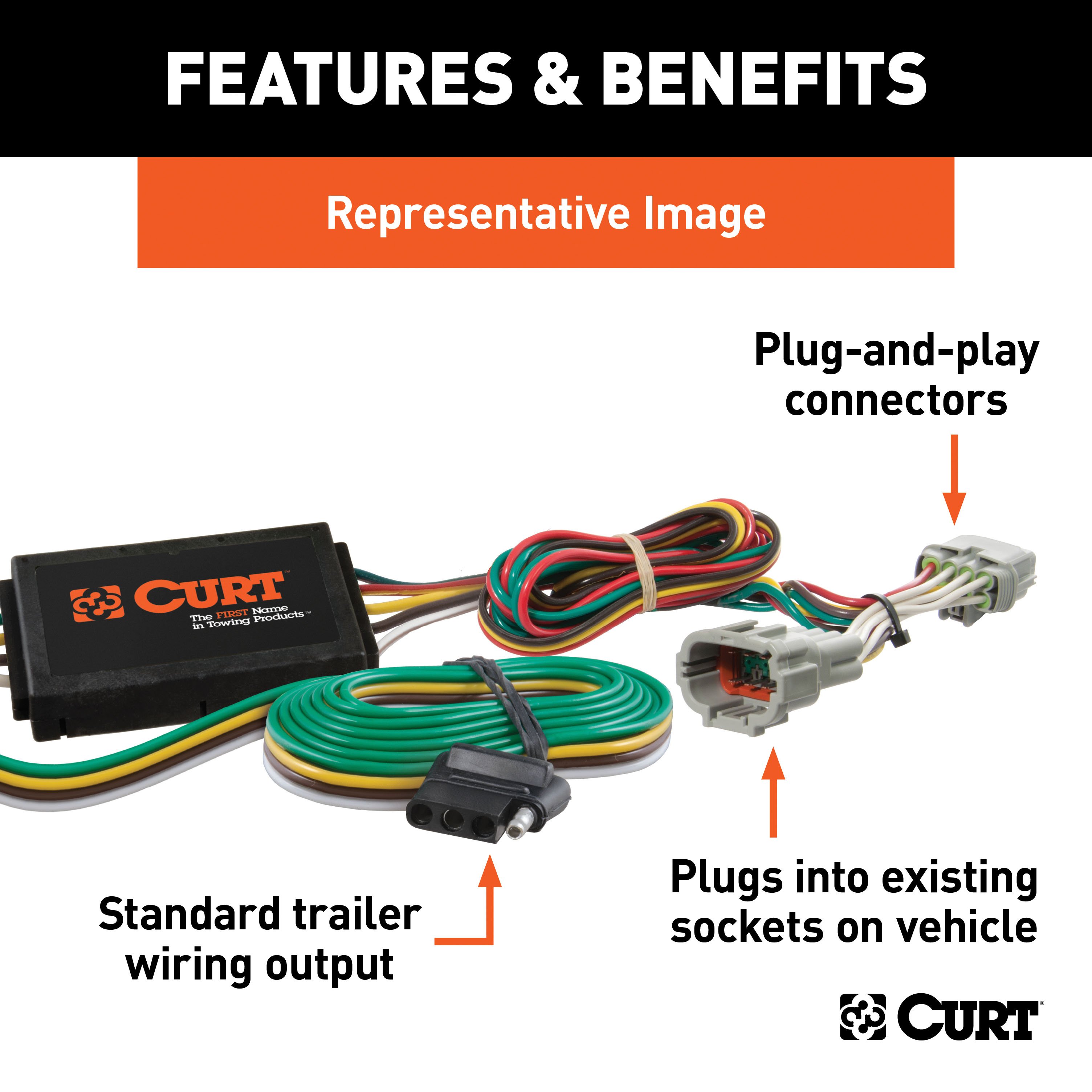
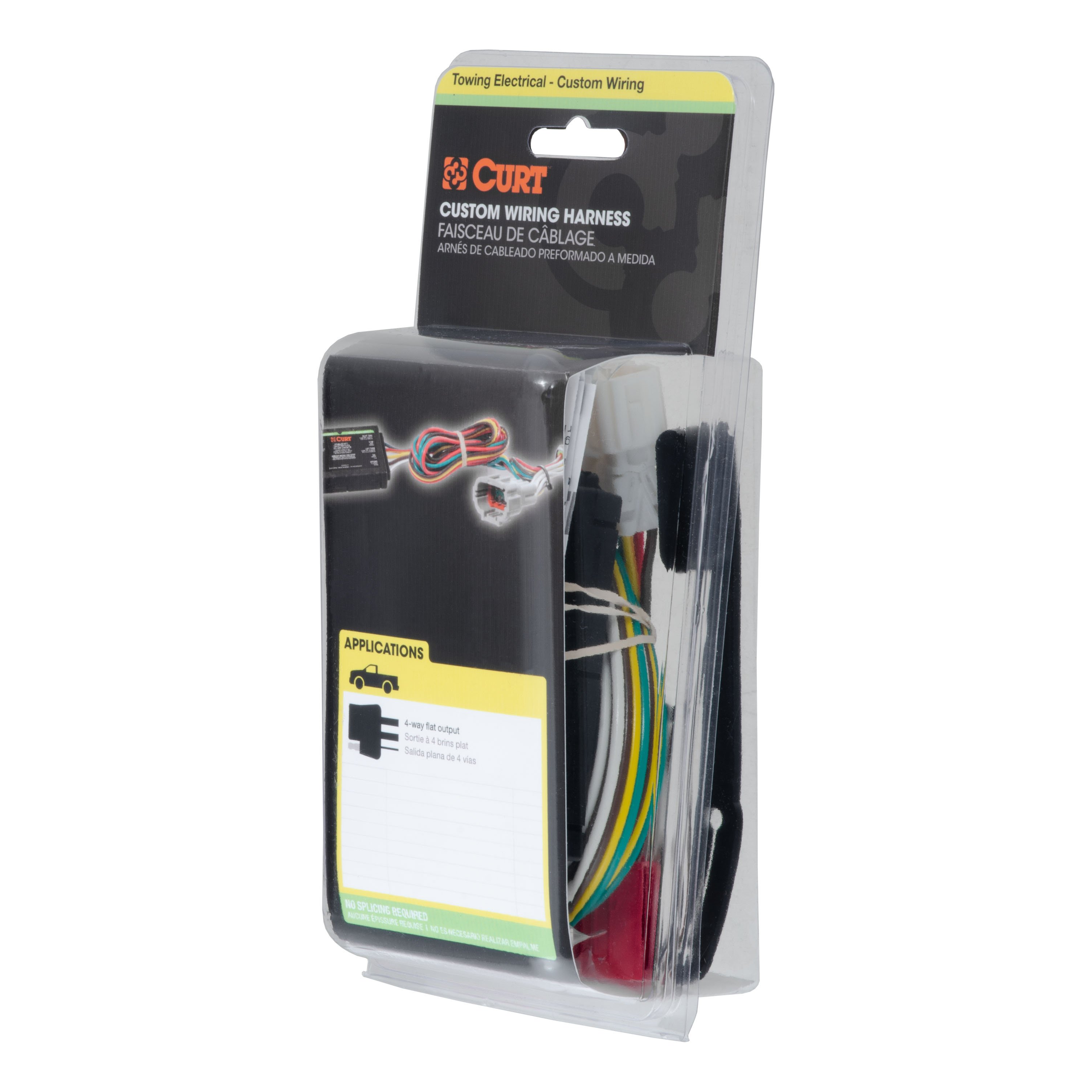
- Includes: Class 1 Trailer Tow Hitch, Custom Wiring Harness
Compatibility Chart
Description
Get Expert Help
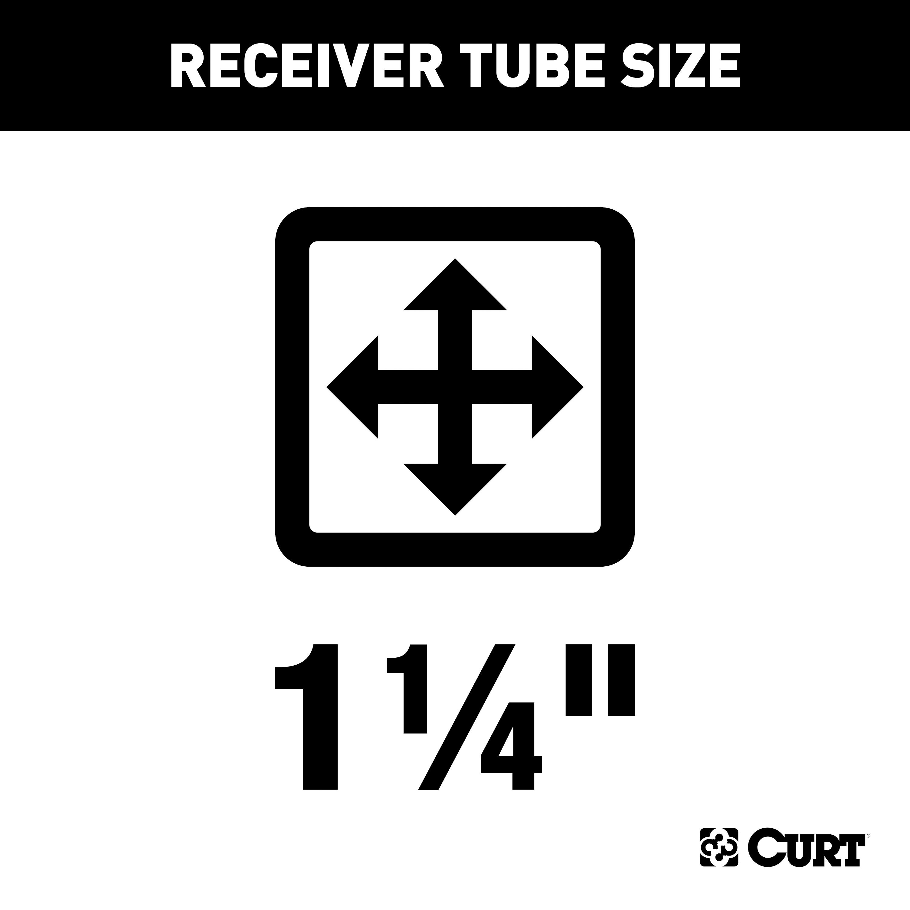
For 2006-2015 Mazda MX-5 Miata Trailer Hitch + Wiring 4 Pin Fits All Models Curt 11028 56082 1-1/4 Tow Receiver Install Notes
Installation Instructions for Mazda MX-5 Miata Convertible (2006-Present)
Part Numbers:
- 11028
Tools Required:
- Socket Wrench
- Torque Wrench
- 9/16" Socket
- 11/16" Socket
- Drill
- 7/16" Drill Bit
- Rotary Tool
- Cutoff Wheel
Hardware List:
- Carriage Bolt: 7/16-14 UNC, 1-1/2", Grade 8, YZ (Qty: 4)
- Square Hole Spacer: 0.250 x 0.88 x 2.25" (Qty: 4)
- Flange Nut: 7/16-14 UNC, Grade 8, YZ (Qty: 4)
- Carriage Bolt: 3/8-16 UNC, 1", Grade 8, YZ (Qty: 8)
- Flange Nut: 3/8-16 UNC, Grade 8, YZ (Qty: 8)
- Driver Side Plate: CM-11028-DS (Qty: 1)
- Passenger Side Plate: CM-11028-PS (Qty: 1)
- Fishwire: 7/16" (Qty: 1)
Step-by-Step Instructions:
-
Trim Rear Fascia:
- Locate the center of the lower rear fascia.
- Trim a 1-3/4" wide by 3/4" tall opening as shown in the Fascia Trim Diagram.
-
Lower Muffler:
- Remove the four (4) rubber isolators holding the muffler to allow for hitch installation.
-
Enlarge Access Holes:
- Remove the plastic caps on the outside of each frame rail.
- Enlarge the access holes using a rotary tool to fit the provided CM-SP2 spacers and 7/16" carriage bolts. Refer to the Hole Enlargement Diagram.
-
Install Center Section:
- Raise the hitch center section into position and install 7/16" carriage bolts and hex flange nuts through the center section straps.
-
Fishwire Frame Hardware:
- Fishwire the 7/16" carriage bolts and CM-SP2 spacers through the enlarged access holes in the frame rails and out the existing holes.
-
Attach Side Plates:
- Raise the side plates into position.
- Secure them to the frame using the hardware from Step 5 and the provided 7/16" hex flange nuts.
-
Attach Center Section to Side Plates:
- Install the eight (8) 3/8" x 1" carriage bolts and flange nuts through the side plates and center section mounting plates. Do not fully tighten.
-
Drill Remaining Frame Holes:
- Using the hitch as a template, drill the remaining holes in the frame rails with a 7/16" drill bit.
-
Fishwire Remaining Hardware:
- Fishwire the remaining 7/16" carriage bolts and CM-SP2 spacers through the access holes and out the drilled holes.
- Secure with 7/16" hex flange nuts.
-
Torque Fasteners:
- Torque all 3/8" fasteners to 45 lb-ft.
- Torque all 7/16" fasteners to 70 lb-ft.
-
Reinstall Muffler and Plastic Caps:
- Reinstall the muffler by reattaching the rubber isolators.
- Replace the plastic plugs removed in Step 3.
Safety Notes:
- Drilling and Fascia Trimming Required: Ensure all cuts are clean and precise for proper hitch fitment.
- Periodically check all fasteners to confirm they remain tight and all components are structurally sound.
Specifications:
- Gross Load Capacity (Weight Carrying Hitch):
- Trailer Weight: 2,000 lbs
- Tongue Weight: 200 lbs
- Hitch Weight: 26 lbs
Installation Time:
- Professional: 90 minutes
- Novice (DIY): 120 minutes
Manufacturer Notes:
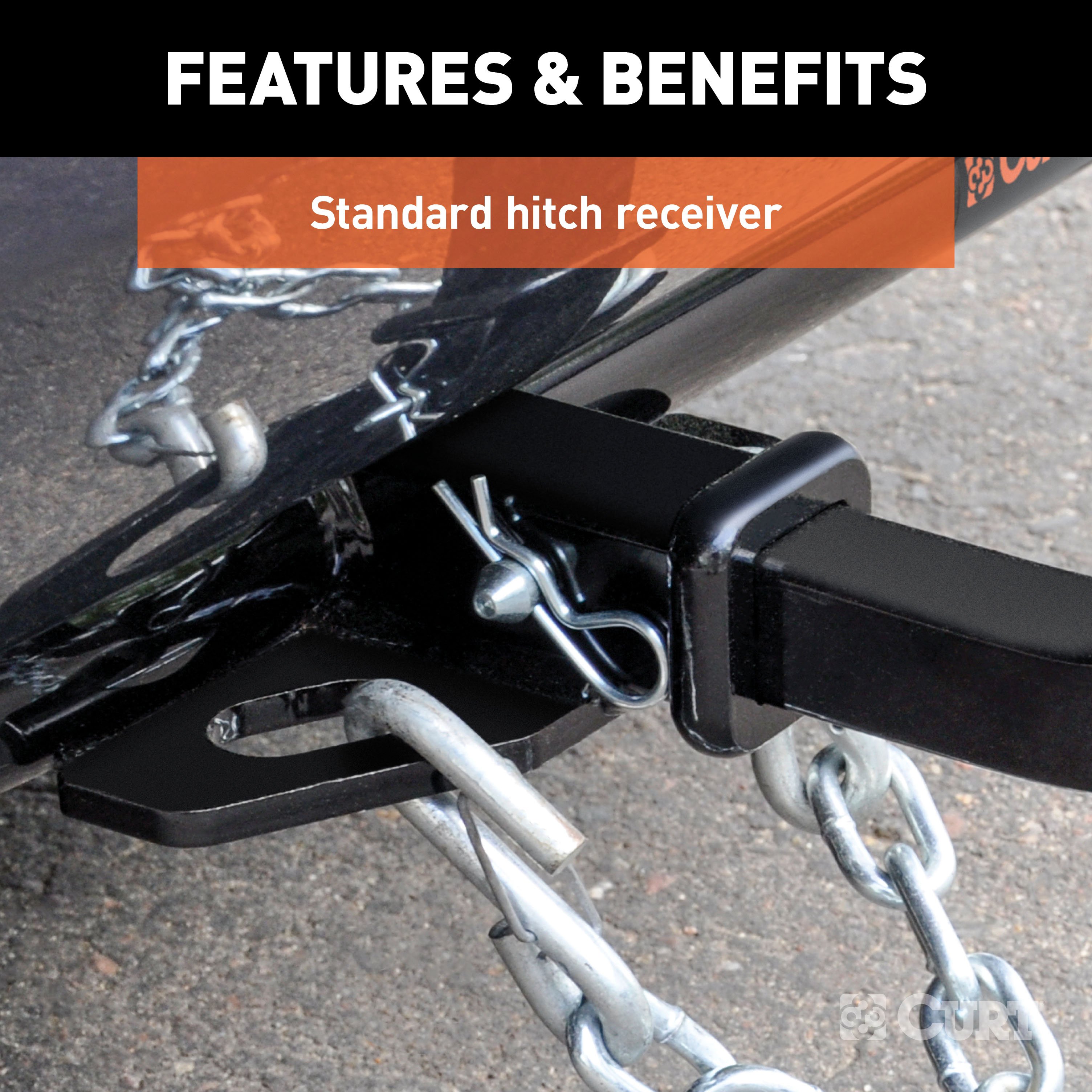
- Designed for use with Ball Mount #55001 / 45501.
- For installation questions, contact Technical Support at 1-877-287-8634.
- Product Warranty: Curt Manufacturing Inc. guarantees this product to be free from defects in material and workmanship.
Warning: Do not exceed the vehicle manufacturer's recommended towing capacity.
Installation Instructions
Tools Required:
- Socket Wrench
- Torque Wrench
- 9/16" Socket
- 11/16" Socket
- Drill
- 7/16" Drill Bit
- Rotary Tool
- Cutoff Wheel
Hardware List:
- Carriage Bolt: 7/16-14 UNC, 1-1/2", Grade 8 (Qty: 4)
- Square Hole Spacer: 0.250 x 0.88 x 2.25" (Qty: 4)
- Flange Nut: 7/16-14 UNC, Grade 8 (Qty: 4)
- Carriage Bolt: 3/8-16 UNC, 1", Grade 8 (Qty: 8)
- Flange Nut: 3/8-16 UNC, Grade 8 (Qty: 8)
- Driver Side Plate: CM-11028-DS (Qty: 1)
- Passenger Side Plate: CM-11028-PS (Qty: 1)
- Fishwire: 7/16" (Qty: 1)
Step-by-Step Instructions:
-
Trim Rear Fascia:
- Locate the center of the lower rear fascia.
- Trim a 1-3/4" wide by 3/4" tall opening as shown in the Fascia Trim Diagram.
-
Lower Muffler:
- Remove the four (4) rubber isolators holding the muffler to allow for hitch installation.
-
Enlarge Access Holes:
- Remove the plastic caps on the outside of each frame rail.
- Enlarge the access holes using a rotary tool to fit the provided CM-SP2 spacers and 7/16" carriage bolts. Refer to the Hole Enlargement Diagram.
-
Install Center Section:
- Raise the hitch center section into position and install 7/16" carriage bolts and hex flange nuts through the center section straps.
-
Fishwire Frame Hardware:
- Fishwire the 7/16" carriage bolts and CM-SP2 spacers through the enlarged access holes in the frame rails and out the existing holes.
-
Attach Side Plates:
- Raise the side plates into position.
- Secure them to the frame using the hardware from Step 5 and the provided 7/16" hex flange nuts.
-
Attach Center Section to Side Plates:
- Install the eight (8) 3/8" x 1" carriage bolts and flange nuts through the side plates and center section mounting plates. Do not fully tighten.
-
Drill Remaining Frame Holes:
- Using the hitch as a template, drill the remaining holes in the frame rails with a 7/16" drill bit.
-
Fishwire Remaining Hardware:
- Fishwire the remaining 7/16" carriage bolts and CM-SP2 spacers through the access holes and out the drilled holes.
- Secure with 7/16" hex flange nuts.
-
Torque Fasteners:
- Torque all 3/8" fasteners to 45 lb-ft.
- Torque all 7/16" fasteners to 70 lb-ft.
-
Reinstall Muffler and Plastic Caps:
- Reinstall the muffler by reattaching the rubber isolators.
- Replace the plastic plugs removed in Step 3.
Safety Notes:
- Drilling and Fascia Trimming Required: Ensure all cuts are clean and precise for proper hitch fitment.
- Periodically check all fasteners to confirm they remain tight and all components are structurally sound.
Specifications:
- Gross Load Capacity (Weight Carrying Hitch):
- Trailer Weight: 2,000 lbs
- Tongue Weight: 200 lbs
- Hitch Weight: 26 lbs
Installation Time:
- Professional: 90 minutes
- Novice (DIY): 120 minutes
Attention: This is a summary of the installation procedure. For complete installation instructions, including diagrams and detailed information from the manufacturer, please download the full installation PDF.
For Technical Support:
For technical support and assistance, our team of experts is available to help. You can reach our tech support by visiting www.trailerjacks.com or calling 877-869-6690.
Warranty Information:
For complete warranty instructions, please download the full installation PDF.
Warning: Do not exceed the vehicle manufacturer's recommended towing capacity. Periodically inspect all components for structural integrity and proper torque.
Installation Instructions for Mazda MX-5 Miata
Part Number:
- 56082
Tools Required:
- Trim puller
- Phillips screwdriver
- 10mm socket
Step-by-Step Instructions:
-
Access the Rear Cargo Area:
- Open the trunk and remove the floor cover, the trim panels on the driver's and passenger's sides, and the rear scuff panel by removing several plastic fasteners using a trim puller.
- Remove the jack storage cover.
-
Locate and Disconnect Taillight Wiring Harness:
- Starting on the passenger side, pull back the rear trim panel to reveal the vehicle's taillight wiring harness.
- The connectors will resemble those on the T-connector.
- Separate the connectors, ensuring not to damage the locking tabs.
-
Install the T-Connector on the Passenger Side:
- Insert the T-connector ends with the red and green wires between the separated connectors.
- Ensure the connectors are fully inserted with locking tabs in place.
-
Route the T-Connector on the Driver's Side:
- Route the T-connector end with the yellow wire out from behind the trim panel across the removed scuff panel to the driver's side.
- Repeat step 2 on the driver's side using the yellow wire.
-
Establish a Ground Connection:
- Locate a suitable grounding point near the connector, such as an existing screw with a nut in the vehicle’s frame.
- If necessary, drill a 3/32” hole and secure the white wire using the provided eyelet and screw.
-
Mount the Converter Box:
- Adhere the black converter box to the frame of the car using the double-sided tape provided.
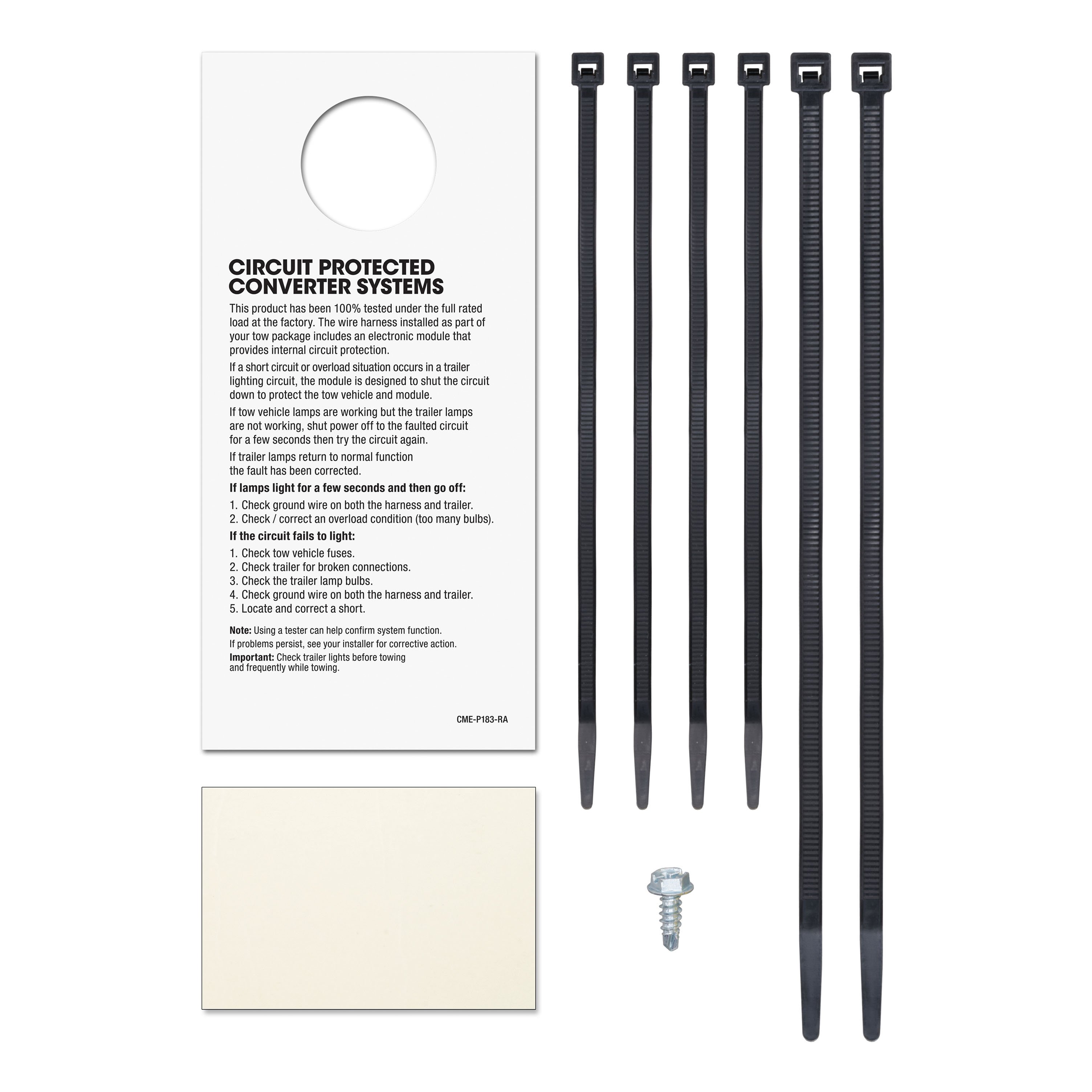
- Secure any loose parts of the T-connector with the provided cable ties.
-
Route the 4-Flat Connector:
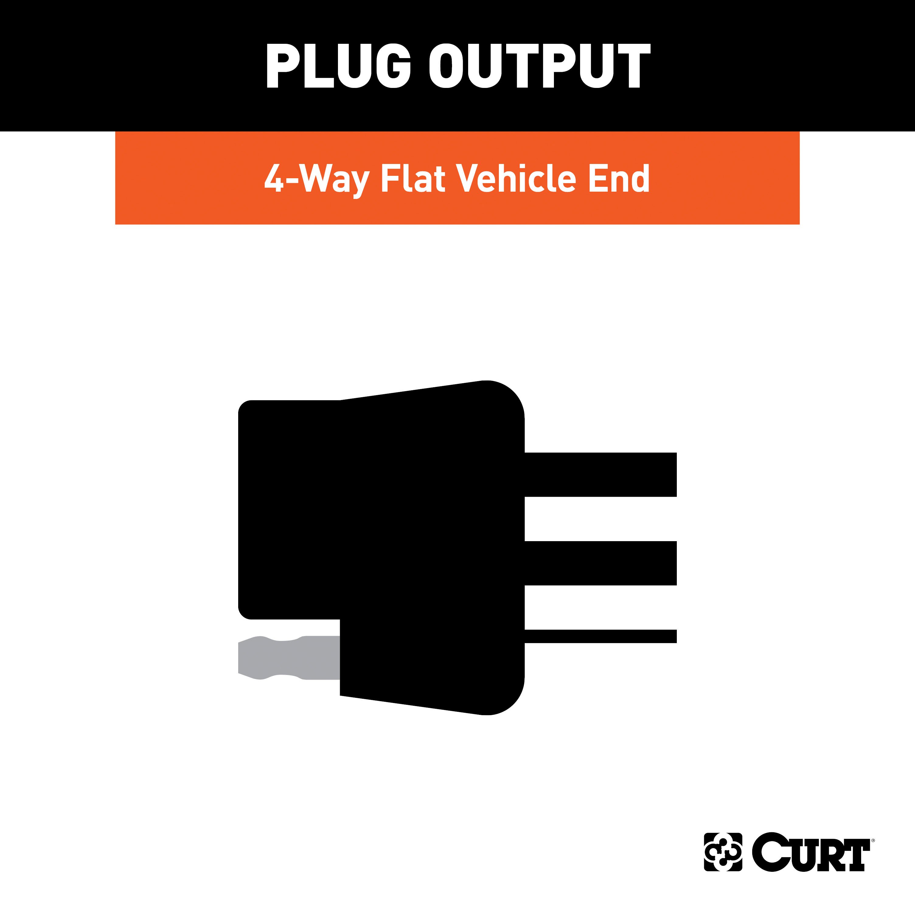
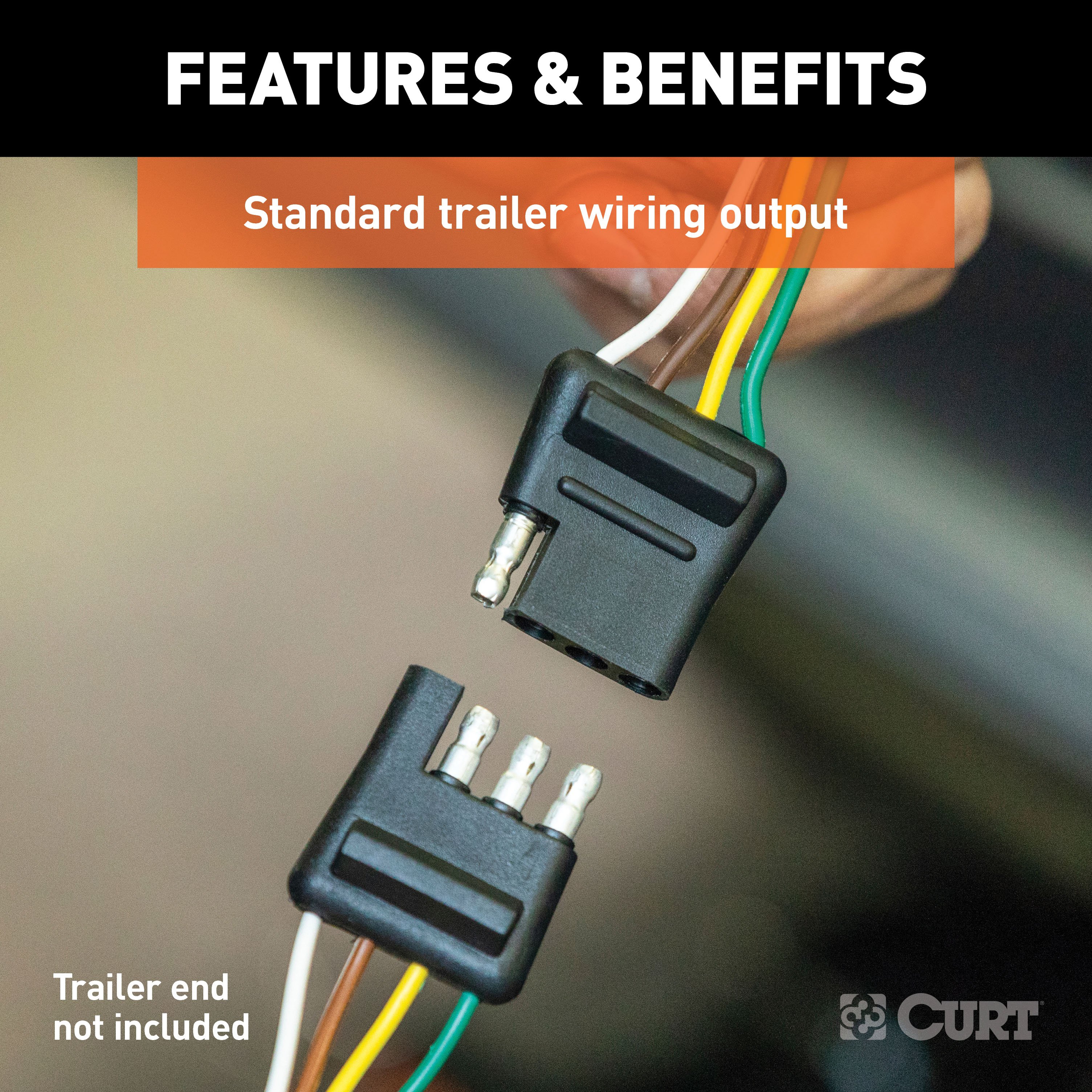
- Route the 4-flat wire out of the jack storage compartment to the center of the vehicle and out the trunk when in use.
- When not in use, roll up and store it in a convenient, out-of-the-way location in the jack storage compartment.
Safety Notes:
- Warning: Verify that there are no miscellaneous items hidden behind or under any surface before drilling to avoid damage and/or personal injury.
Note: After installation, test the wiring with a properly wired trailer or test light to confirm functionality.
Important Information:
- Attention: This is a summary of the installation procedure. For complete installation instructions, including diagrams and detailed information from the manufacturer, please download the full installation PDF.
- For technical support and assistance, our team of experts is available to help. You can reach our tech support by visiting www.trailerjacks.com or calling 877-869-6690.
- Warranty Information: For complete warranty instructions, please download the full installation PDF.


