





For 2007-2018 BMW X5 Trailer Hitch + Wiring 4 Pin Fits All Models Curt 13077 59236 2 inch Tow Receiver
Model: 13077 59236-CH164This Trailer Tow Hitch + 4-Flat Fits The Following Vehicles:
2007 - 2018 BMW X5 All Models
This Trailer Tow Hitch + 4-Flat Includes the Following Parts:
- Class 3 Trailer Hitch, 2" Receiver (Easy Bolt-On, No Drilling)
- Multi-Function Taillight Converter Kit (Requires Splicing)
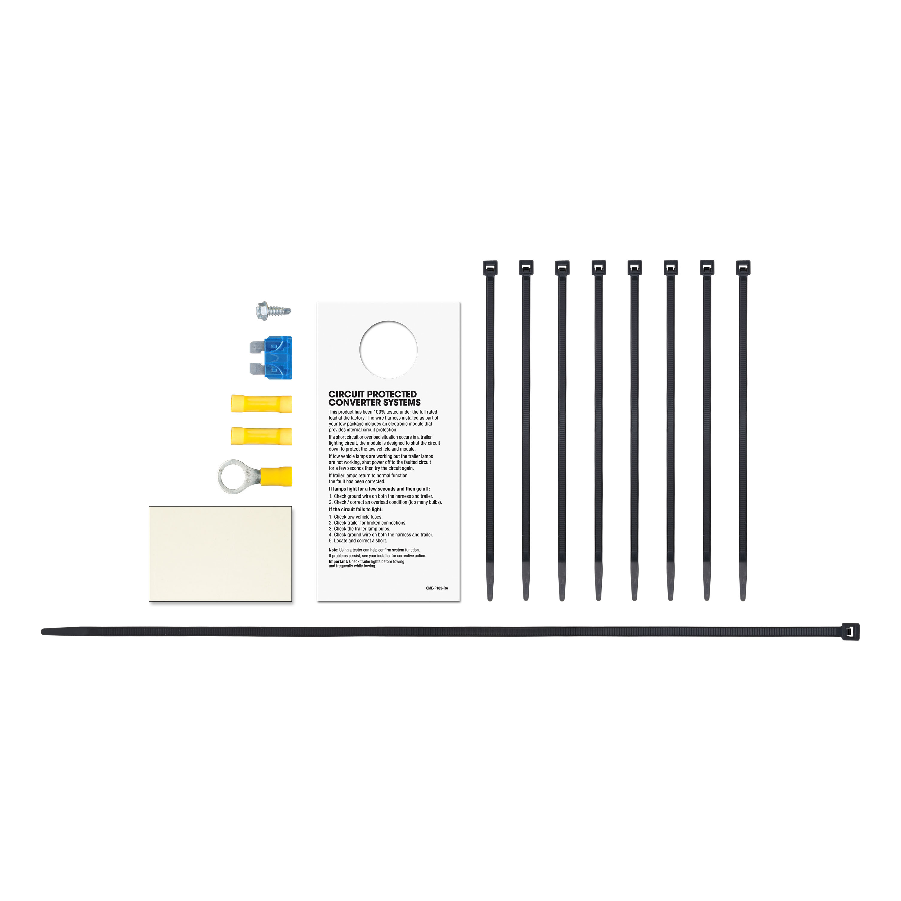
- Installation instructions, schematics, diagrams, and hardware (if required).
List of Fitment Years:
2007, 2008, 2009, 2010, 2011, 2012, 2013, 2014, 2015, 2016, 2017, 2018
CURT 13077 Class 3 Trailer Hitch, 2-Inch Receiver
Manufactured by: Curt
Whatever your task at hand -- whether it's launching that boat before daybreak, setting up your camper before the rush or getting a final load to the dump before close -- CURT class 3 trailer hitches offer the strength needed for serious towing They make it easy to hitch up and Bring It, offering a vehicle-specific fit and the weight capacity to handle a variety of trailers Custom class 3 hitches are the most common type of receiver hitch for pickup trucks and SUVs.
Because of their weight range, they are also found on full-size cars, crossovers and minivans Each custom-fit class 3 hitch package is made for vehicle-specific mounting This particular kit fits certain years of the BMW X5 and X6 (see application info to verify vehicle compatibility).
It provides a weight carrying capacity of 6,000 lbs GTW and 600 lbs TW.
It is also compatible with a weight distribution hitch for level towing and a rating of 6,000 lbs WD and 600 lbs WDTW.
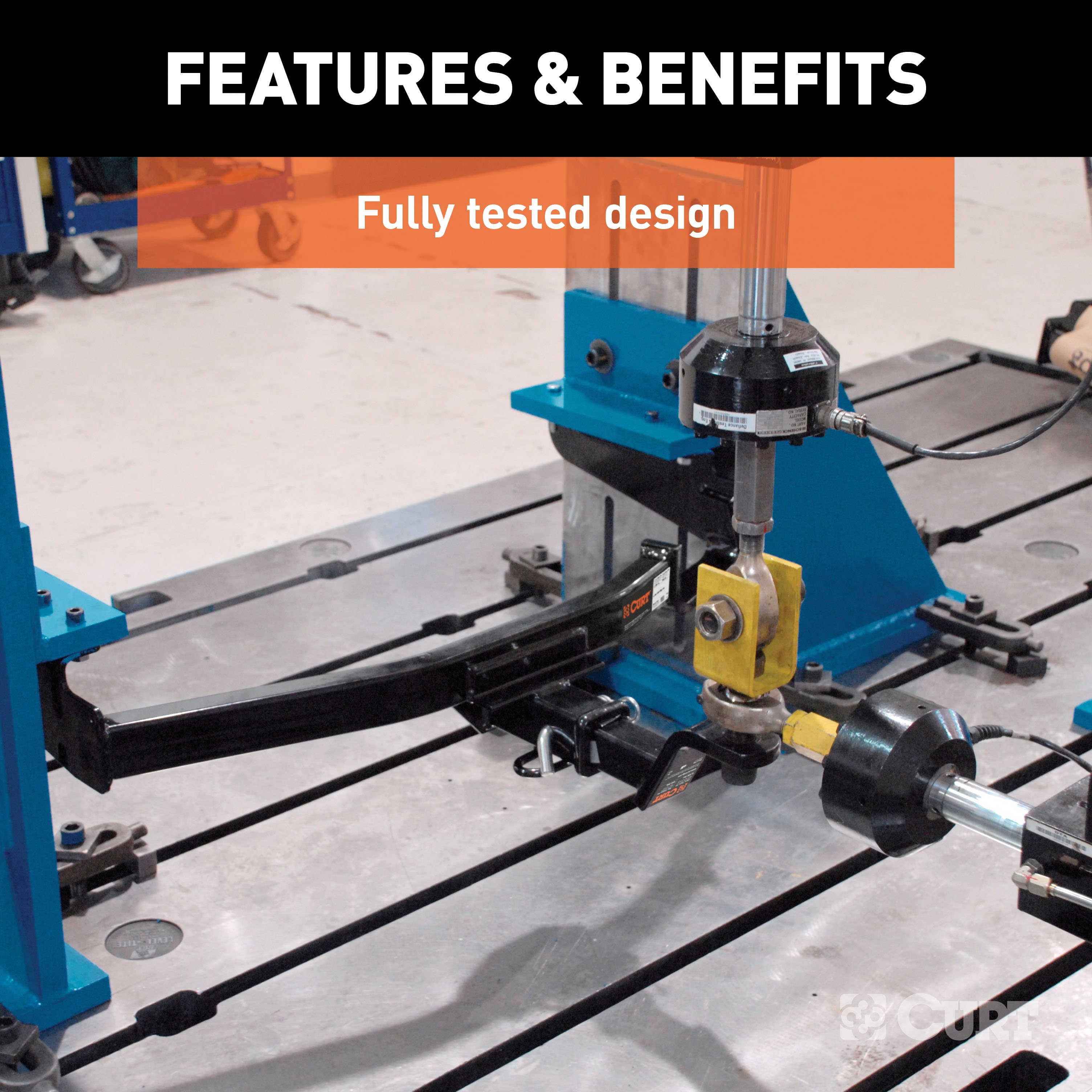
CURT class 3 trailer hitches are typically used to attach and haul utility trailers, boat trailers, campers, snowmobile or ATV haulers and more (NOTE: Never exceed the lowest-rated towing component) Each class 3 hitch has a 2" receiver tube and is tested in accordance with SAE J684 for safety To ensure that CURT class 3 receiver hitches have what it takes for serious trailering, they are designed using a hands-on approach and are constructed with rugged, high-strength steel and precise welding.
We also protect our class 3 hitches in a co-cured finish of liquid A-coat and black powder coat for superior resistance to rust, chipping and UV damage..
Features:
- Rated to 6,000 lbs. gross trailer weight and 600 lbs. tongue weight
- Compatible with weight distribution hitch (6,000 lbs. WD / 600 lbs. WDTW)
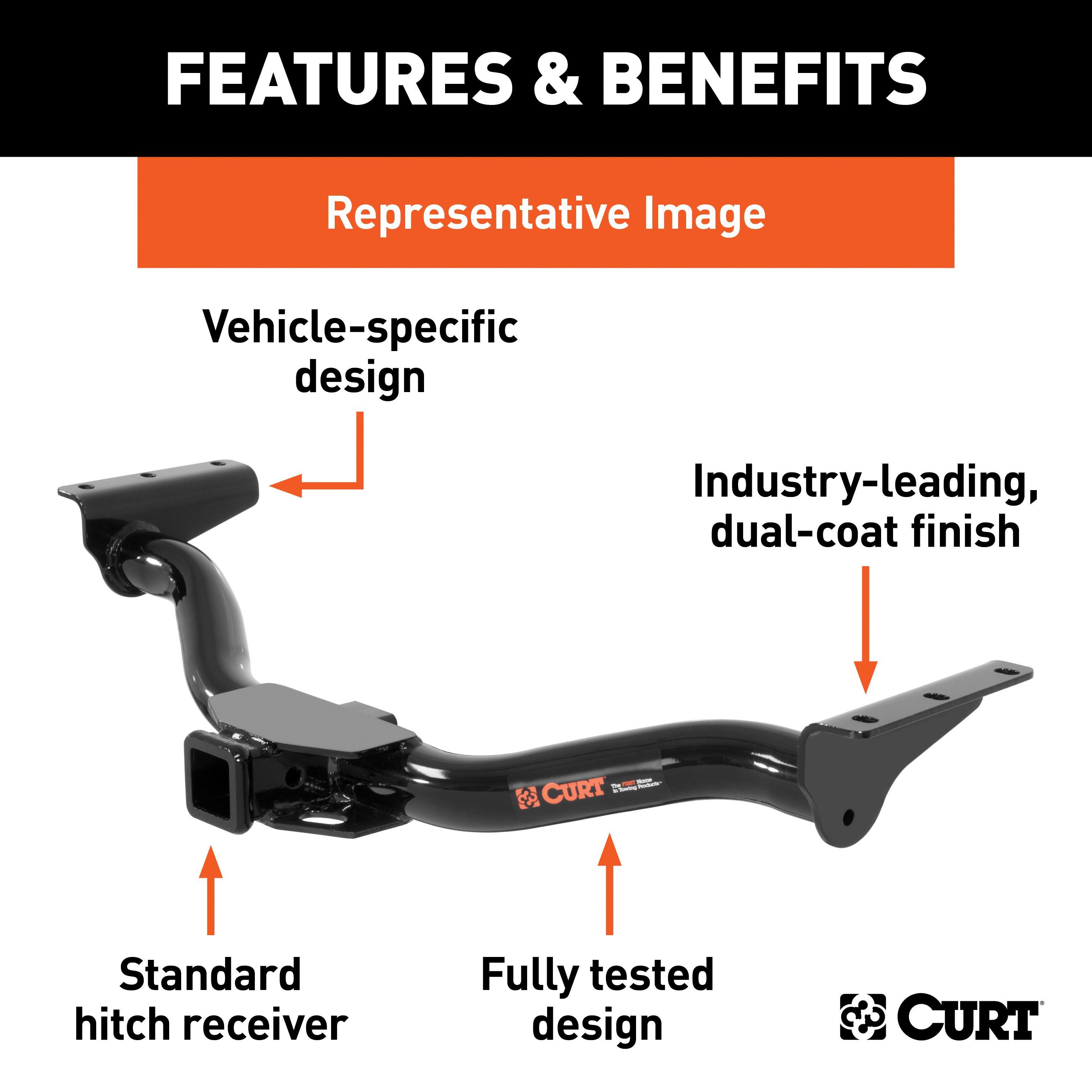
- Engineered with a vehicle-specific design for a custom fit
- Concealed main body for OE look and seamless integration with the vehicle
- Tested for safety in accordance with SAE J684
- Precisely welded for superior strength and fit
- Protected by a durable high-gloss black powder coat finish
- Co-cured in a rust-resistant liquid A-coat, inside and out
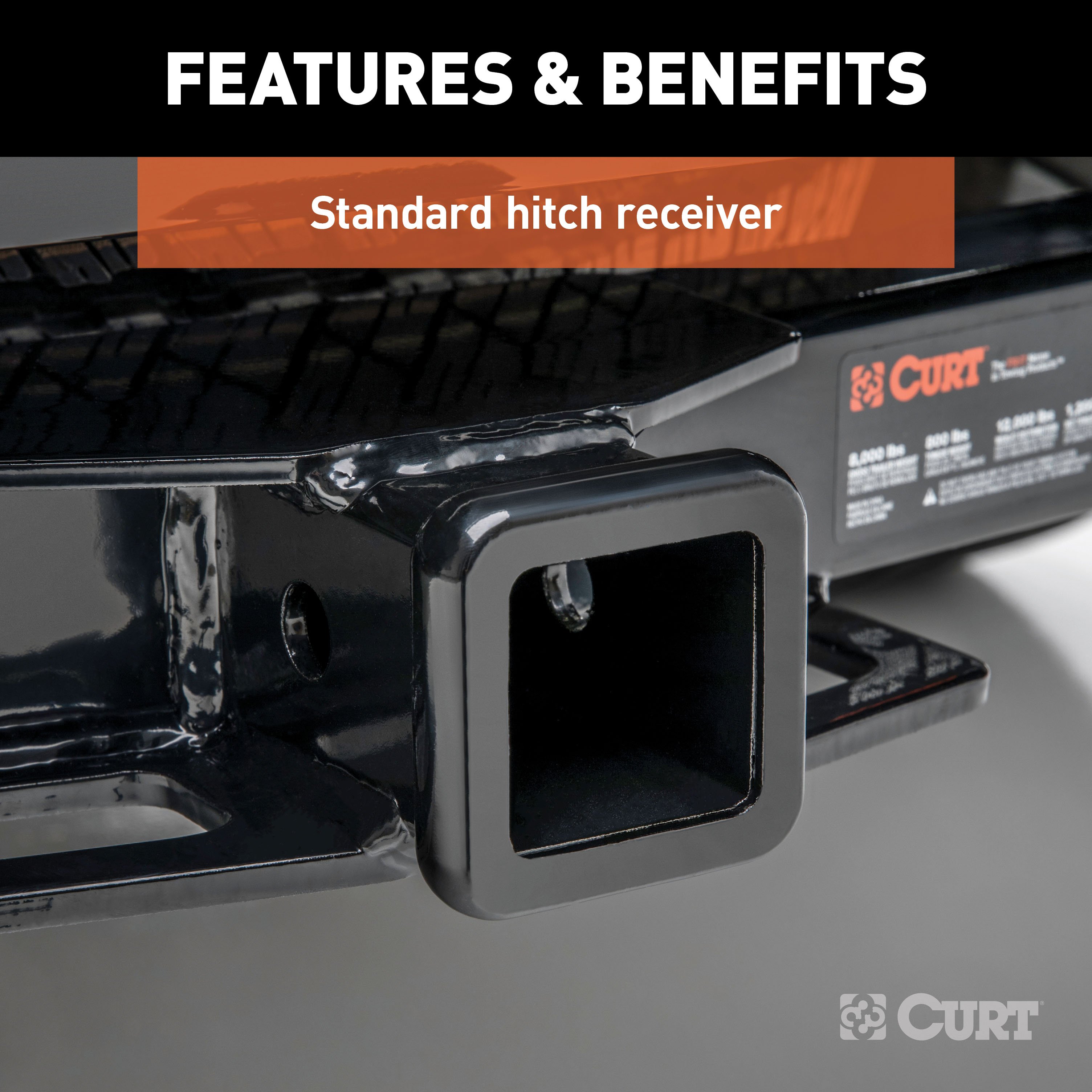
- Equipped with an open-back receiver for easy cleaning
- Limited lifetime warranty (one-year finish, one-year parts)
- Made in USA (may include imported hardware)
CURT 59236 Weather-Resistant Multi-Function Splice-in Trailer Tail Light Converter Kit, 4-Pin Wiring Harness
Manufactured by: Curt
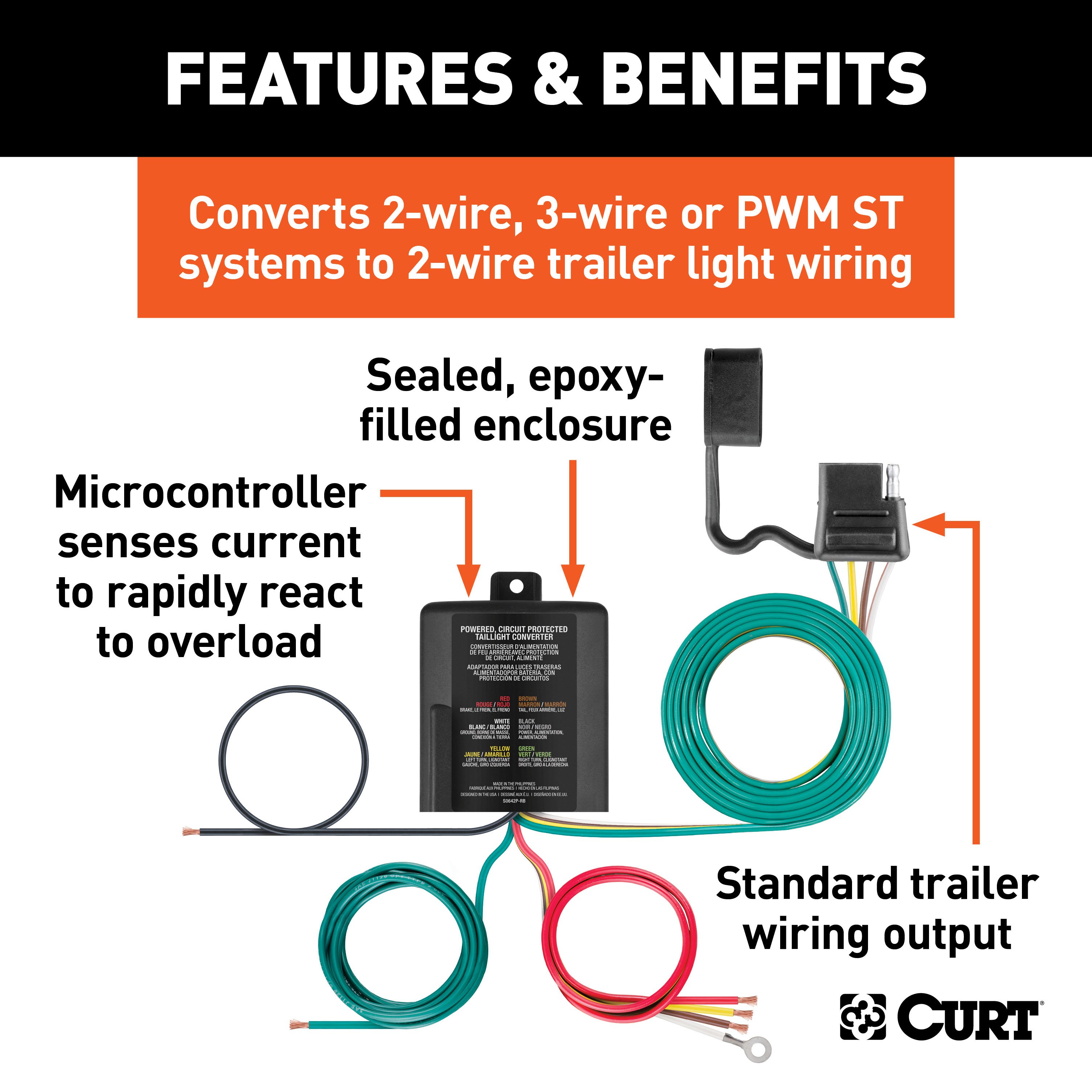
Rain, road grime and salt can deal a vicious blow to your trailer wiring, and it takes electrical components with an extra-thick shell to stand up to the elements The CURT multi-function electrical converter is an advanced taillight converter that offers the ultimate in vehicle compatibility and weather resistance, giving you a reliable wiring connection any season of the year The potted design seals the internal electrical components in a watertight enclosure and is filled with a solid compound to protect against impacts, vibrations and moisture for long-lasting use, even on the exterior of the vehicle.
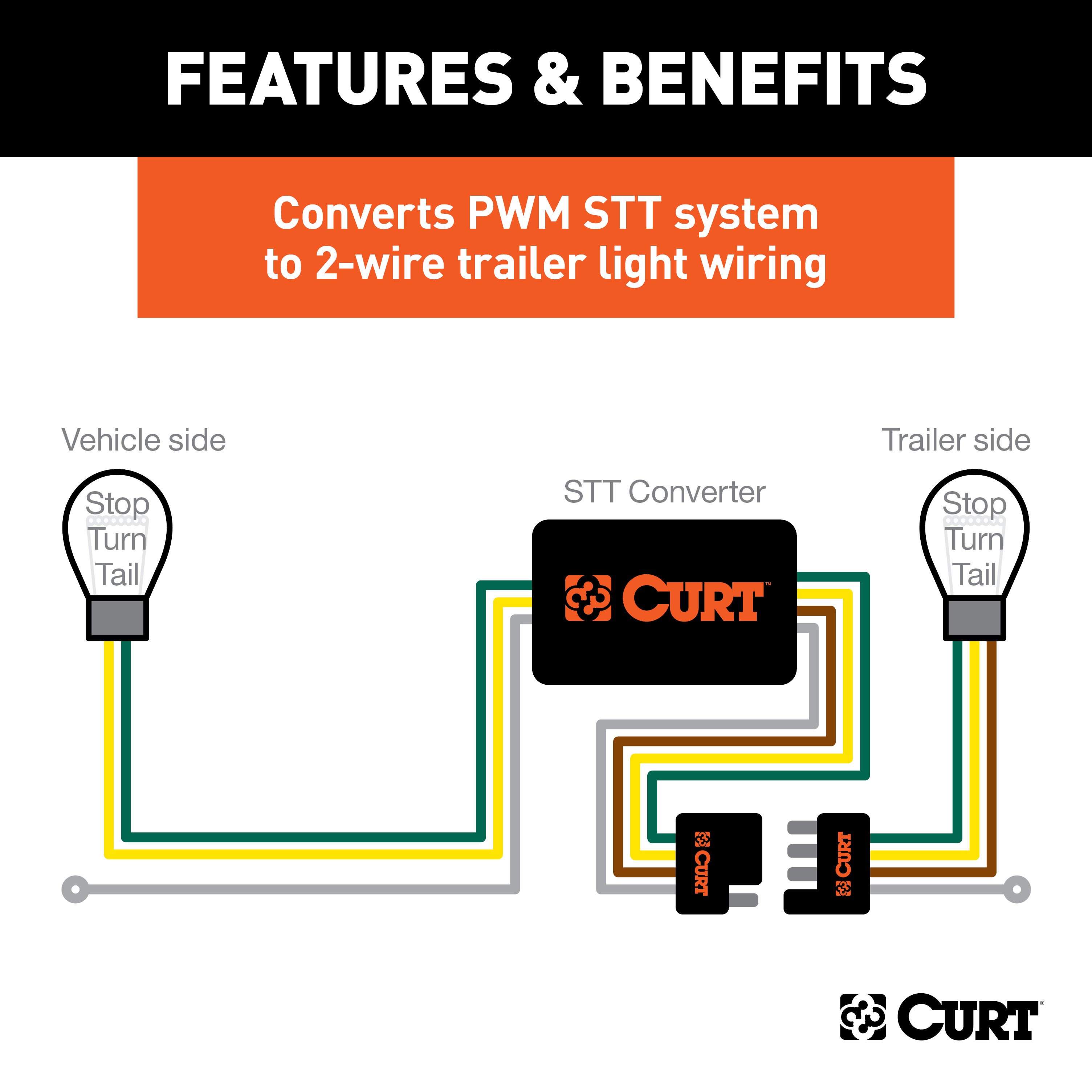
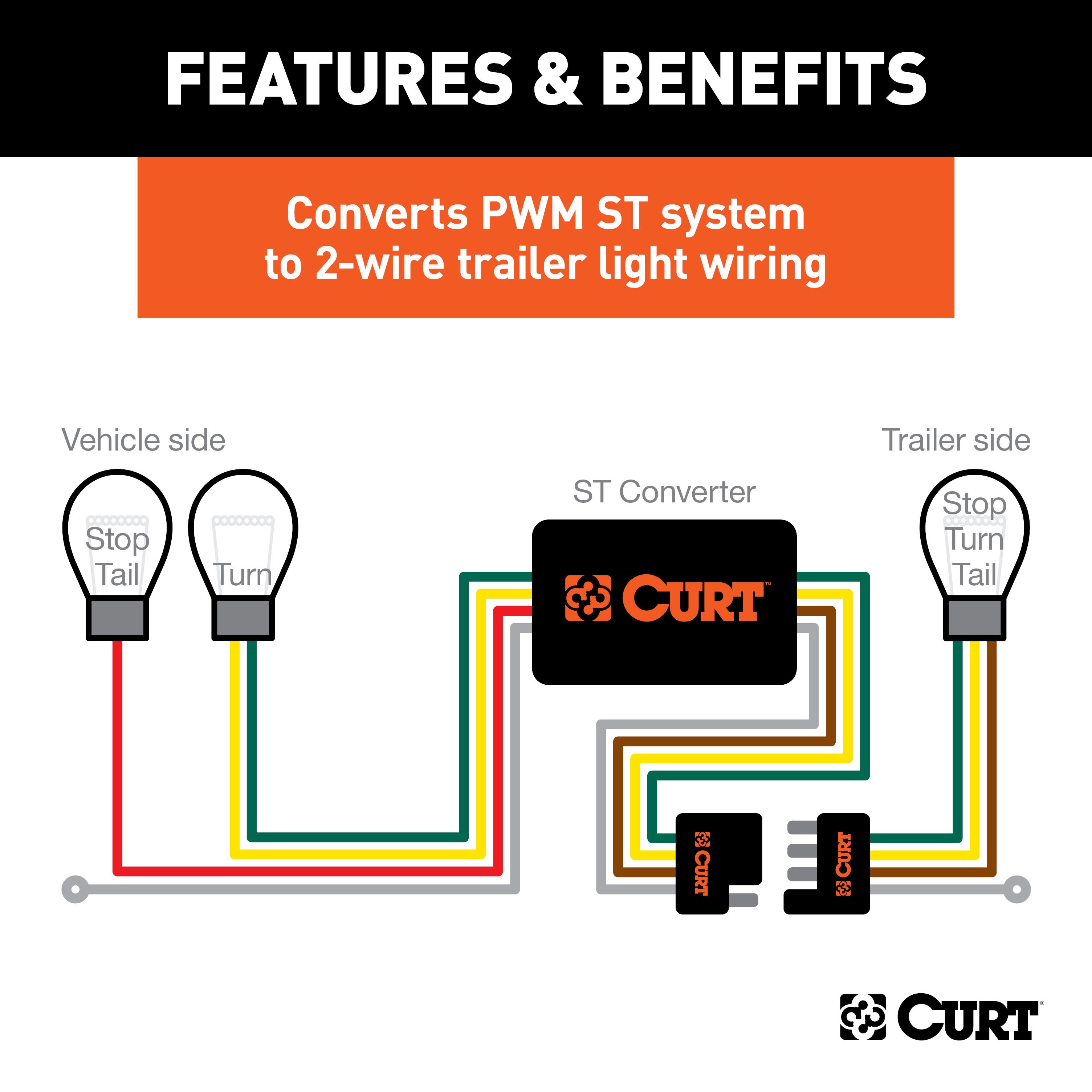
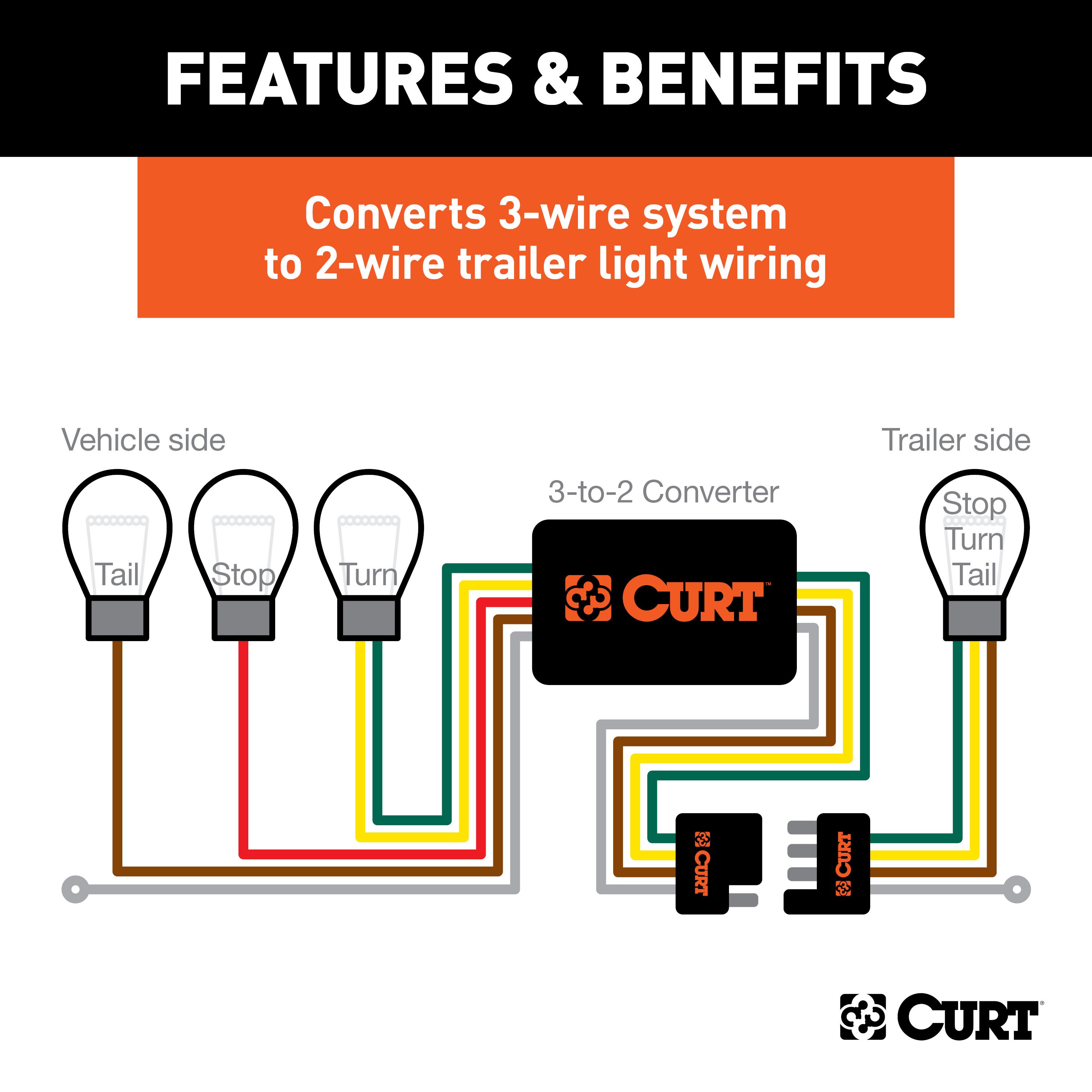
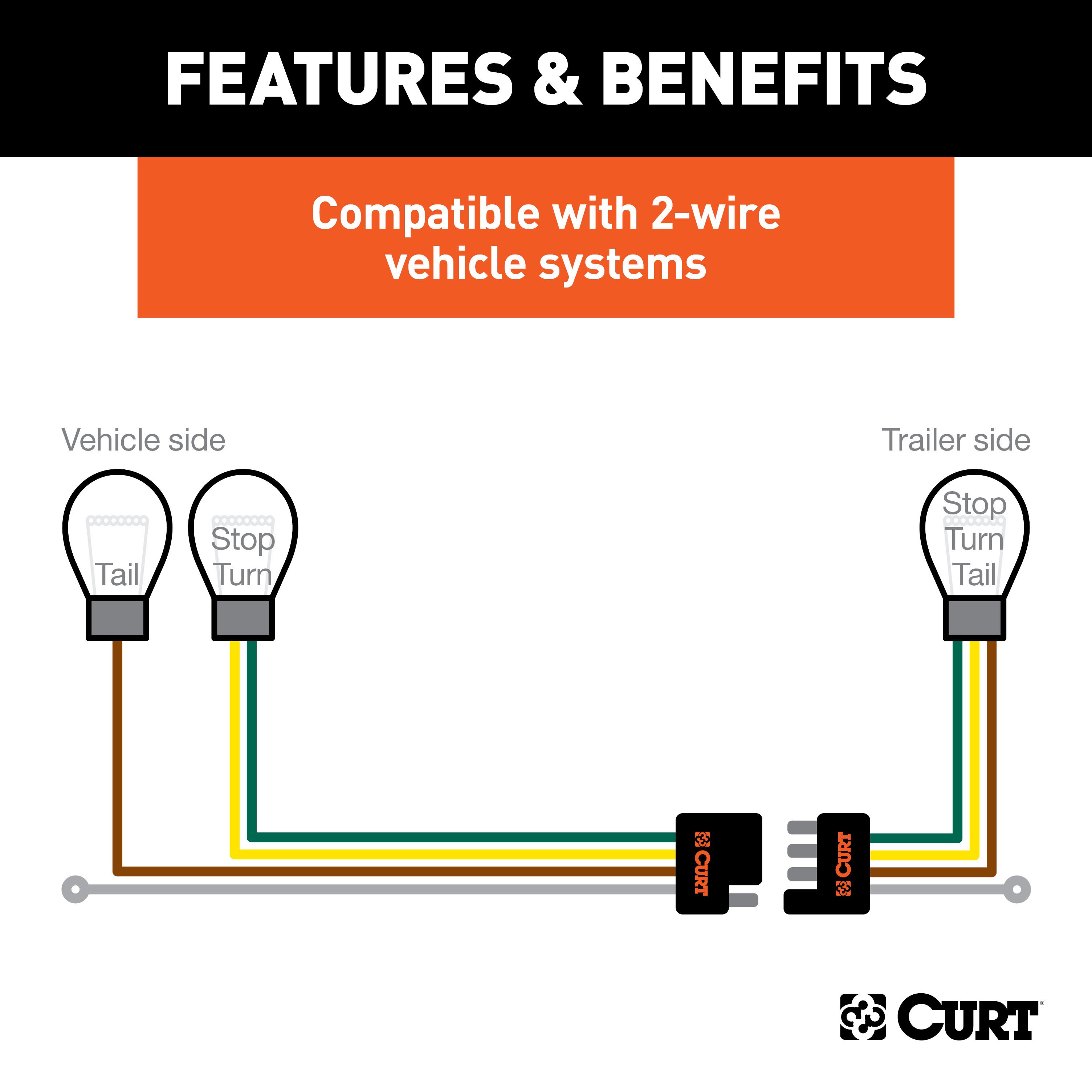
The converter also features our advanced surface mount technology (SMT), using smaller components mounted directly to the surface of the circuit board This produces lower resistance, reduced heat generation, longer life cycles and higher reliability The CURT multi-function electrical converter comes with pigtail wires that are able to be spliced into two-wire, three-wire or PWM wiring system with combined stop and taillights.
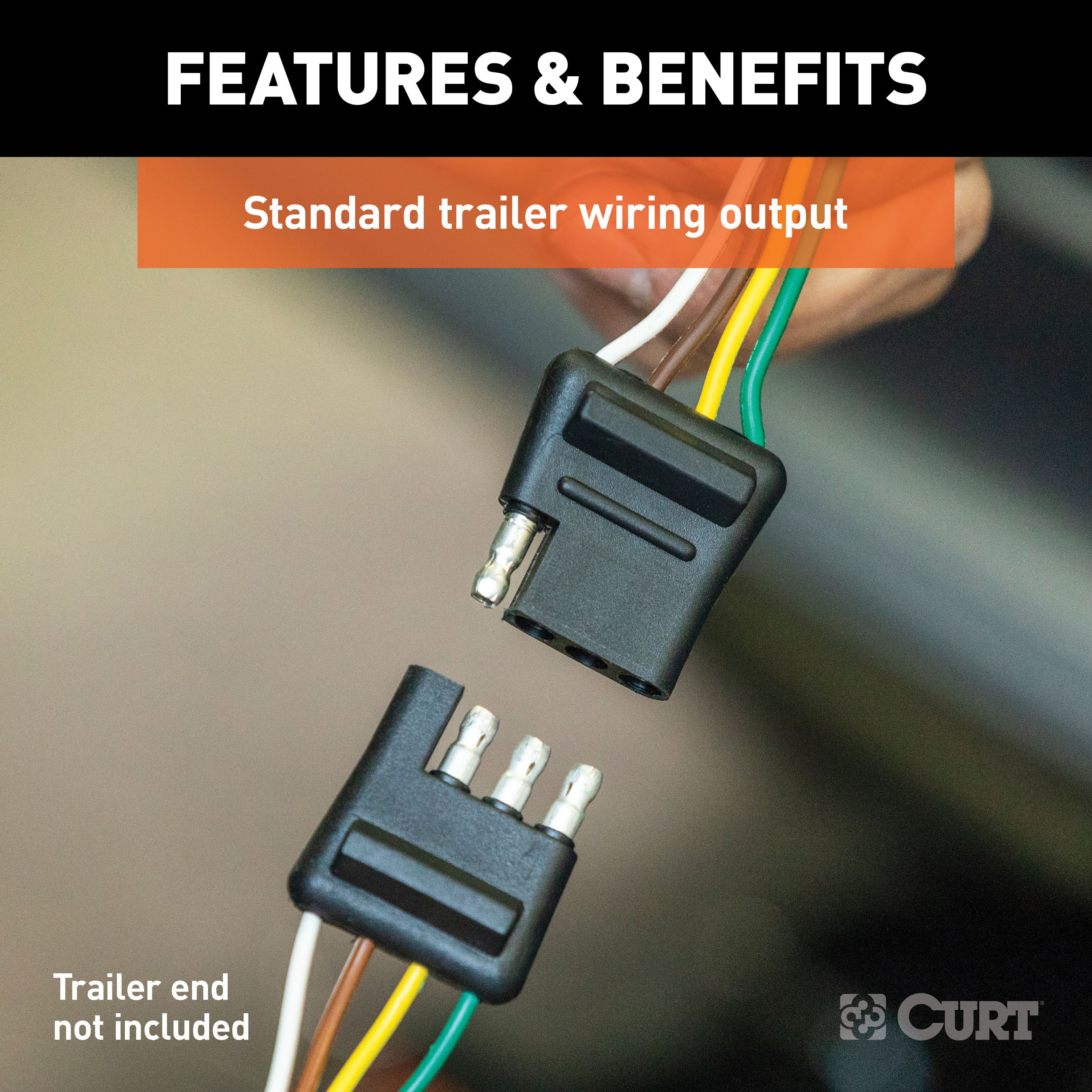
It converts any of these systems to a simple two-wire system, using a standard 4-way flat output, to be compatible with most trailer wiring The converter is controlled using a microprocessor that is able to sense the current passing through it, allowing for quick reaction to dangerous conditions such as overload and short circuits It also filters unwanted input signals to protect your wiring systems and uses a mere seven volts for low-voltage operation.
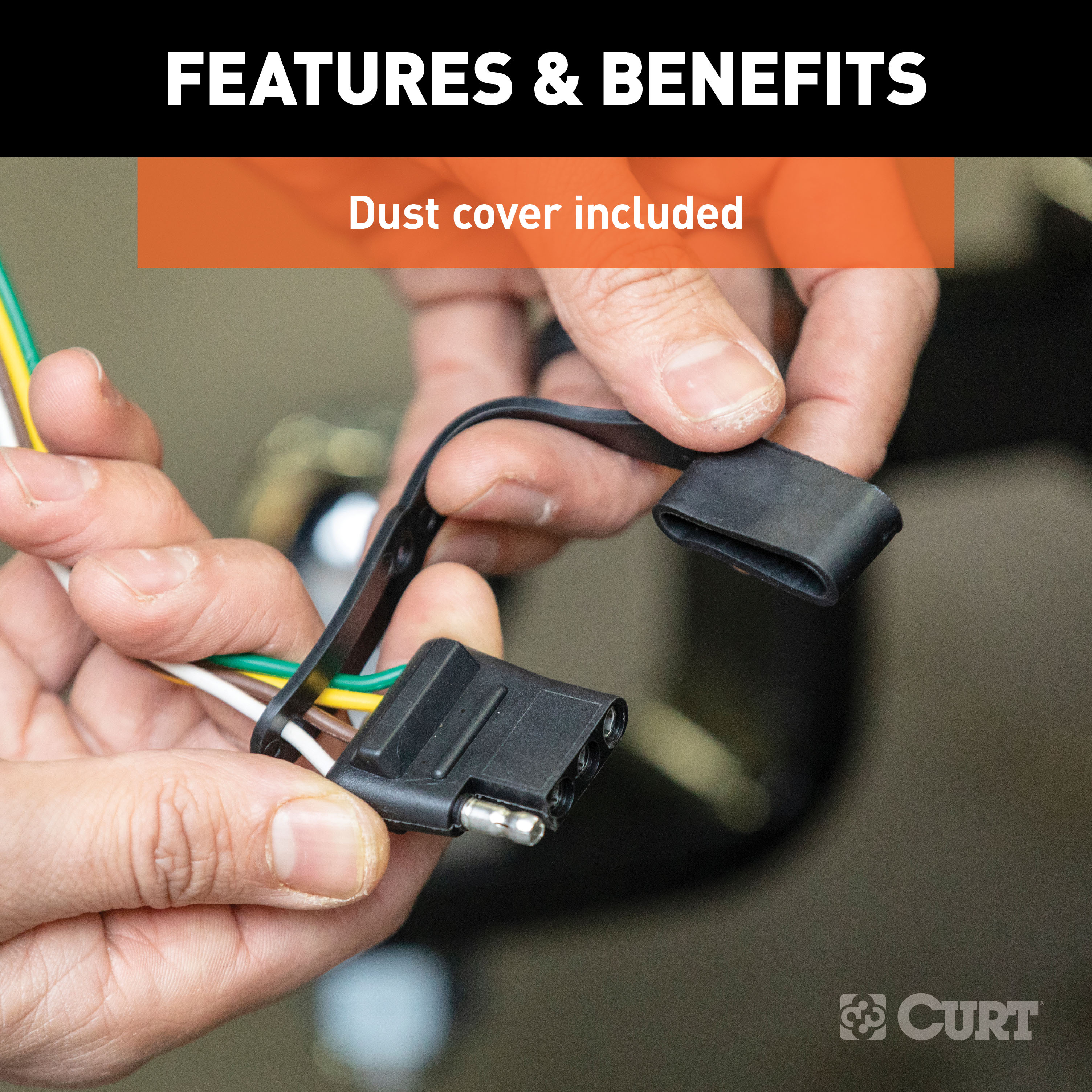
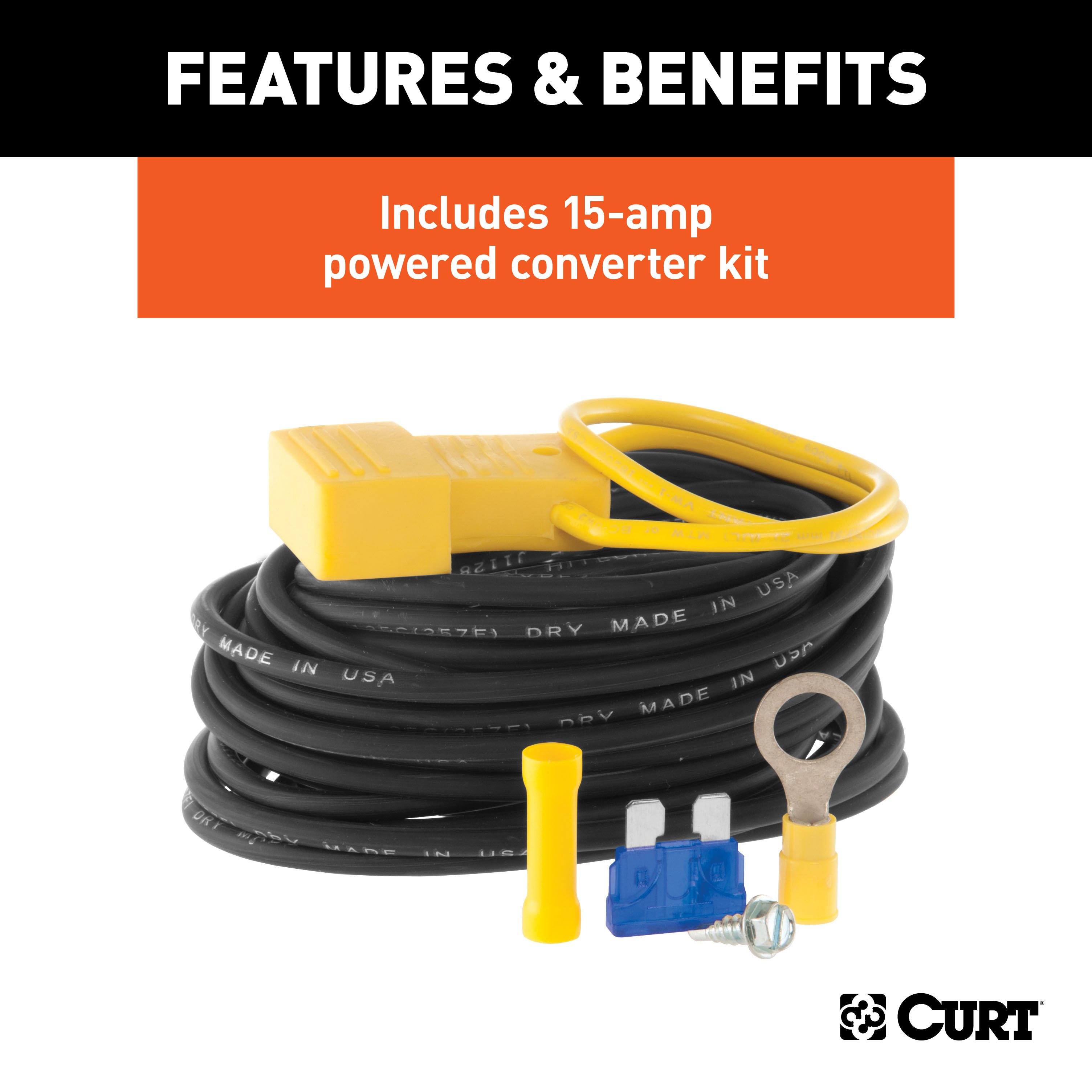
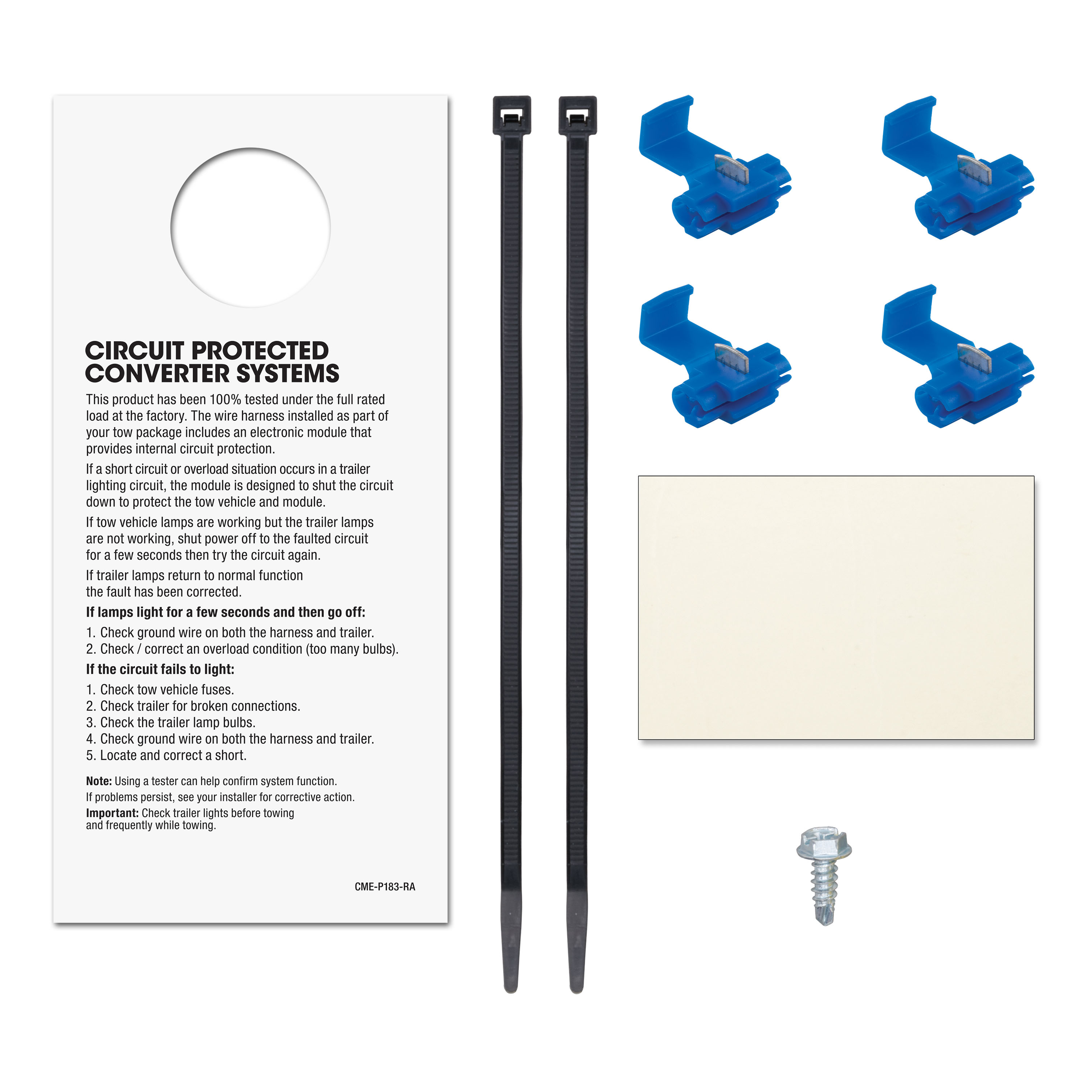
The CURT multi-function taillight converter is a heavy-duty electrical converter for virtually any vehicle-trailer combination It comes with color-coded wires and an easy-to-read wiring guide, as well as a dust cover to protect the 4-way flat connector This package includes a powered converter wiring kit #55152 and four snap locks for faster, more secure splicing..
Features:
- Converts 2-wire, 3-wire or PWM ST system to 2-wire trailer light wiring
- Potted enclosure significantly increases water and vibration resistance
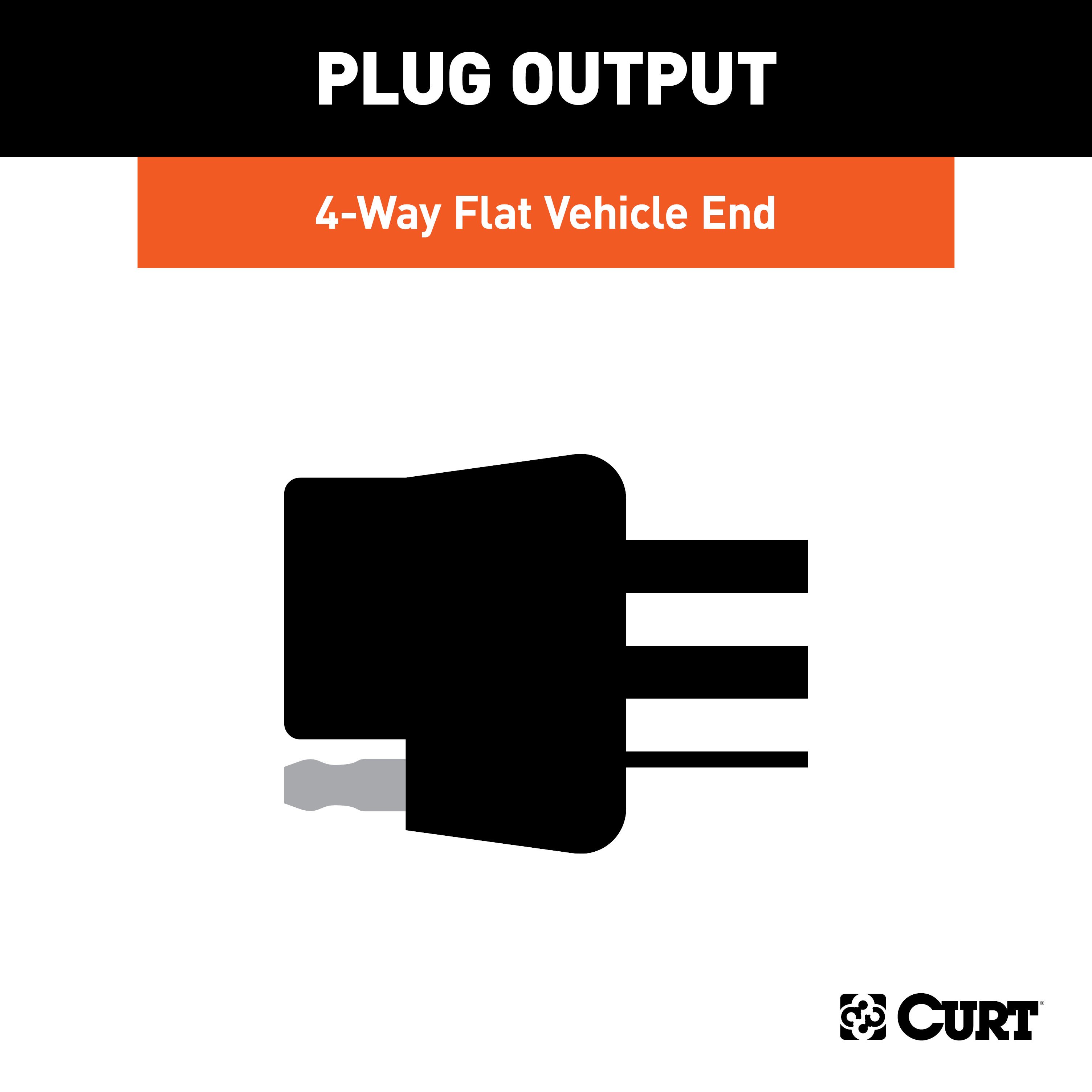
- 4-way flat output connects tail lights, brake lights and turn signals
- Constructed with SMT circuitry for better performance and durability
- Microcontroller senses current to rapidly react to overload
- Provides improved overload, short-circuit and thermal protection
- Low-voltage operation allows function down to seven volts
- Color-coded wires with wiring guide for easier installation
- Included wiring kit allows for a convenient connection to the vehicle battery
- Snap locks included for fast, secure splicing
- Dust cover included to keep connector clean when not in use
Hitches Near Me: We operate out of several warehouses across the country, ensuring faster delivery to your location.
$370 99 $565.90 34% OFF
- Best Price on Web Guarantee
- Fastest Shipping
- FREE Shipping
- In Stock

We match lower prices from major authorized retailers for brand-new products in original packaging, provided the item is in stock. The competing seller must be an authorized, professional retail business; offers from
individuals, auctions, peer-to-peer sites, or unauthorized sellers don’t qualify. Used, refurbished, or open-box items are excluded.
Please see our full terms for details.
Verify Fitment
View products that fit your vehicle
Fits 's with the following styles:
View products that fit your vehicle
Fits 's with the following styles:
$565.90 $370 99
 Learn more
Questions? Call our Auto Experts at (877) 869-6690
Get it now, pay later
Select installments at checkout to split your purchase into 4 interest-free payments of $ every 2 weeks.
- No fees, ever.
- No impact on your credit score.
Payment options are offered by Affirm and are subject to an eligibility check and might not be available in all states. CA Residents: Loans by Affirm Loan Services, LLC are made or arranged pursuant to a California Finance Lender license.
Installments in partnership with


Each may be shipped from a separate location, and therefore, may arrive at different times
Product Details
- Brand: Curt
- Model: 13077 59236-CH164
- Includes: Class 3 Trailer Tow Hitch, Multi-Function Taillight Converter Kit
Compatibility Chart
| Year Range | Make | Model | Style |
|---|
| Default | |
| Brand | Curt |
| Gross Towing Weight | 6,000 LB |
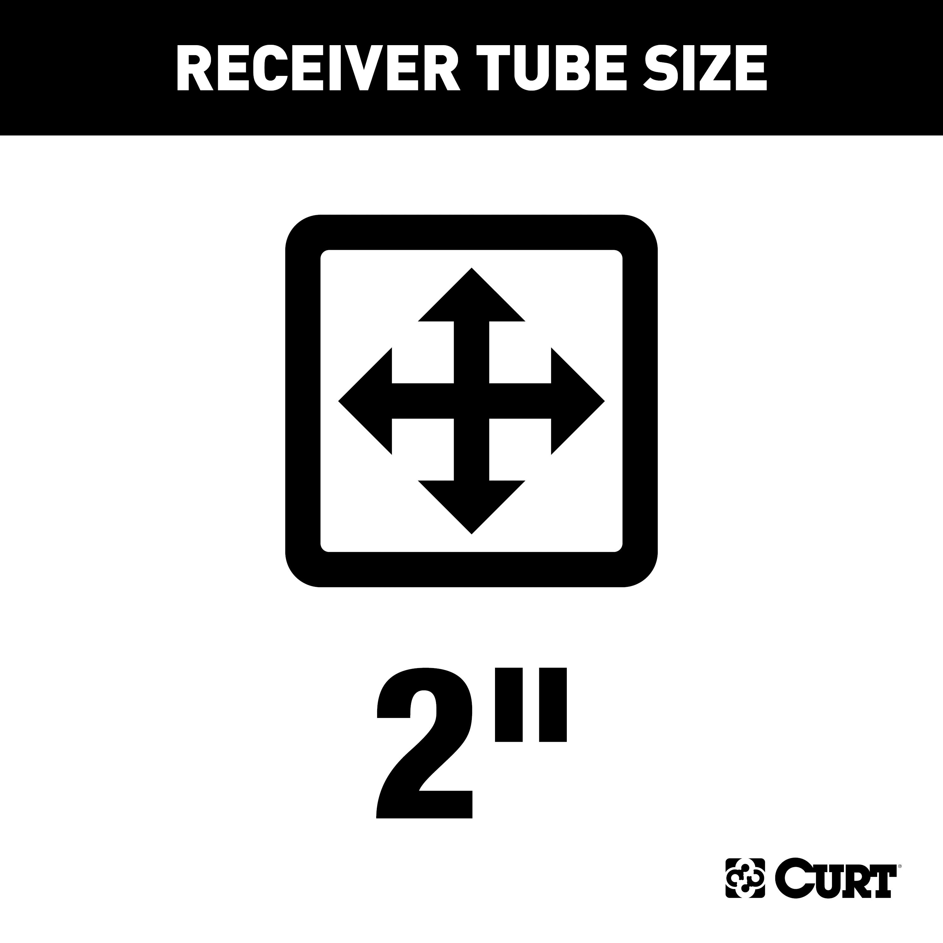
| Trailer Hitch Receiver Size | 2 Inch |
| Trailer Wiring Output Type | 4-Flat |
| Hitch Class | 3 |
| Trailer Wiring Install Style | Hardwire |
| Drilling Required | No |
| Tongue Weight Capacity | 600 LB |
| Gross Towing Weight w/ Weight Distribution Kit | 6,000 LB |
| Maximum Tongue Weight w/ Weight Distribution Kit | 600 LB |
| Hitch Visibility | Concealed |
| Cross-Tube Type | Round Tube |
Ask a Question about For 2007-2018 BMW X5 Trailer Hitch + Wiring 4 Pin Fits All Models Curt 13077 59236 2 inch Tow Receiver
Be the first to ask a question.
Description
This Trailer Tow Hitch + 4-Flat Fits The Following Vehicles:
2007 - 2018 BMW X5 All Models
This Trailer Tow Hitch + 4-Flat Includes the Following Parts:
- Class 3 Trailer Hitch, 2" Receiver (Easy Bolt-On, No Drilling)
- Multi-Function Taillight Converter Kit (Requires Splicing)
- Installation instructions, schematics, diagrams, and hardware (if required).
List of Fitment Years:
2007, 2008, 2009, 2010, 2011, 2012, 2013, 2014, 2015, 2016, 2017, 2018
CURT 13077 Class 3 Trailer Hitch, 2-Inch Receiver
Manufactured by: Curt
Whatever your task at hand -- whether it's launching that boat before daybreak, setting up your camper before the rush or getting a final load to the dump before close -- CURT class 3 trailer hitches offer the strength needed for serious towing They make it easy to hitch up and Bring It, offering a vehicle-specific fit and the weight capacity to handle a variety of trailers Custom class 3 hitches are the most common type of receiver hitch for pickup trucks and SUVs.
Because of their weight range, they are also found on full-size cars, crossovers and minivans Each custom-fit class 3 hitch package is made for vehicle-specific mounting This particular kit fits certain years of the BMW X5 and X6 (see application info to verify vehicle compatibility).
It provides a weight carrying capacity of 6,000 lbs GTW and 600 lbs TW.
It is also compatible with a weight distribution hitch for level towing and a rating of 6,000 lbs WD and 600 lbs WDTW.
CURT class 3 trailer hitches are typically used to attach and haul utility trailers, boat trailers, campers, snowmobile or ATV haulers and more (NOTE: Never exceed the lowest-rated towing component) Each class 3 hitch has a 2" receiver tube and is tested in accordance with SAE J684 for safety To ensure that CURT class 3 receiver hitches have what it takes for serious trailering, they are designed using a hands-on approach and are constructed with rugged, high-strength steel and precise welding.
We also protect our class 3 hitches in a co-cured finish of liquid A-coat and black powder coat for superior resistance to rust, chipping and UV damage..
Features:
- Rated to 6,000 lbs. gross trailer weight and 600 lbs. tongue weight
- Compatible with weight distribution hitch (6,000 lbs. WD / 600 lbs. WDTW)
- Engineered with a vehicle-specific design for a custom fit
- Concealed main body for OE look and seamless integration with the vehicle
- Tested for safety in accordance with SAE J684
- Precisely welded for superior strength and fit
- Protected by a durable high-gloss black powder coat finish
- Co-cured in a rust-resistant liquid A-coat, inside and out
- Equipped with an open-back receiver for easy cleaning
- Limited lifetime warranty (one-year finish, one-year parts)
- Made in USA (may include imported hardware)
CURT 59236 Weather-Resistant Multi-Function Splice-in Trailer Tail Light Converter Kit, 4-Pin Wiring Harness
Manufactured by: Curt
Rain, road grime and salt can deal a vicious blow to your trailer wiring, and it takes electrical components with an extra-thick shell to stand up to the elements The CURT multi-function electrical converter is an advanced taillight converter that offers the ultimate in vehicle compatibility and weather resistance, giving you a reliable wiring connection any season of the year The potted design seals the internal electrical components in a watertight enclosure and is filled with a solid compound to protect against impacts, vibrations and moisture for long-lasting use, even on the exterior of the vehicle.
The converter also features our advanced surface mount technology (SMT), using smaller components mounted directly to the surface of the circuit board This produces lower resistance, reduced heat generation, longer life cycles and higher reliability The CURT multi-function electrical converter comes with pigtail wires that are able to be spliced into two-wire, three-wire or PWM wiring system with combined stop and taillights.
It converts any of these systems to a simple two-wire system, using a standard 4-way flat output, to be compatible with most trailer wiring The converter is controlled using a microprocessor that is able to sense the current passing through it, allowing for quick reaction to dangerous conditions such as overload and short circuits It also filters unwanted input signals to protect your wiring systems and uses a mere seven volts for low-voltage operation.
The CURT multi-function taillight converter is a heavy-duty electrical converter for virtually any vehicle-trailer combination It comes with color-coded wires and an easy-to-read wiring guide, as well as a dust cover to protect the 4-way flat connector This package includes a powered converter wiring kit #55152 and four snap locks for faster, more secure splicing..
Features:
- Converts 2-wire, 3-wire or PWM ST system to 2-wire trailer light wiring
- Potted enclosure significantly increases water and vibration resistance
- 4-way flat output connects tail lights, brake lights and turn signals
- Constructed with SMT circuitry for better performance and durability
- Microcontroller senses current to rapidly react to overload
- Provides improved overload, short-circuit and thermal protection
- Low-voltage operation allows function down to seven volts
- Color-coded wires with wiring guide for easier installation
- Included wiring kit allows for a convenient connection to the vehicle battery
- Snap locks included for fast, secure splicing
- Dust cover included to keep connector clean when not in use
Hitches Near Me: We operate out of several warehouses across the country, ensuring faster delivery to your location.


