




For 2011-2019 Ford Explorer Trailer Wiring 7 Way Trailer Wiring Plug w/ Bracket Fits All Models Curt
Model: 56306 58290-CW1260This Wiring 7-Way + Bracket Fits The Following Vehicles:
2011 - 2019 Ford Explorer All Models
This Wiring 7-Way + Bracket Includes the Following Parts:
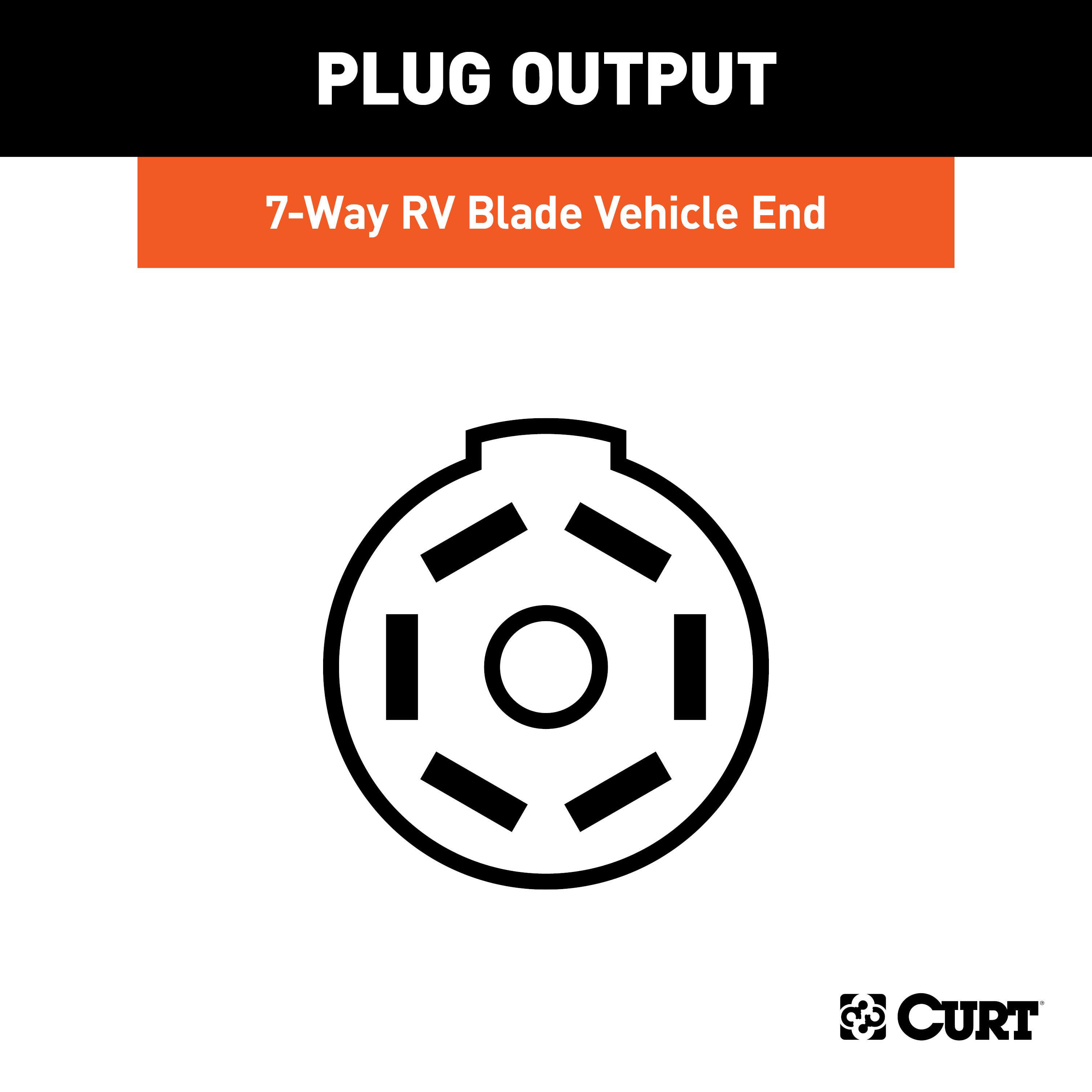
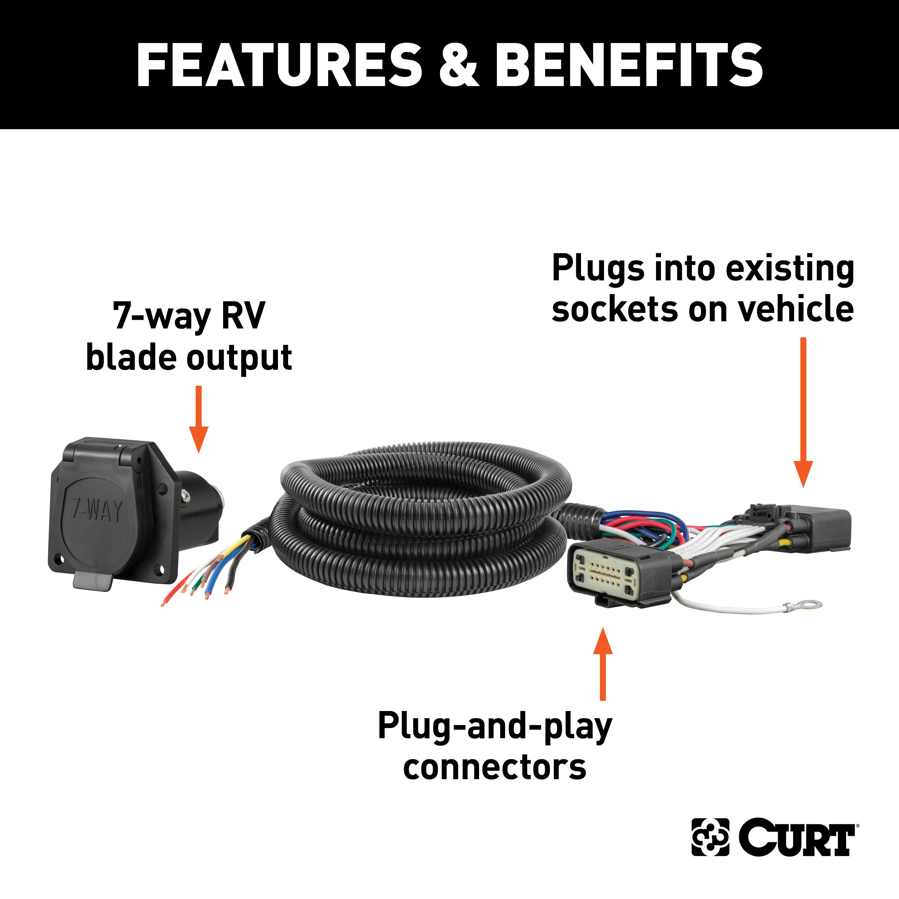
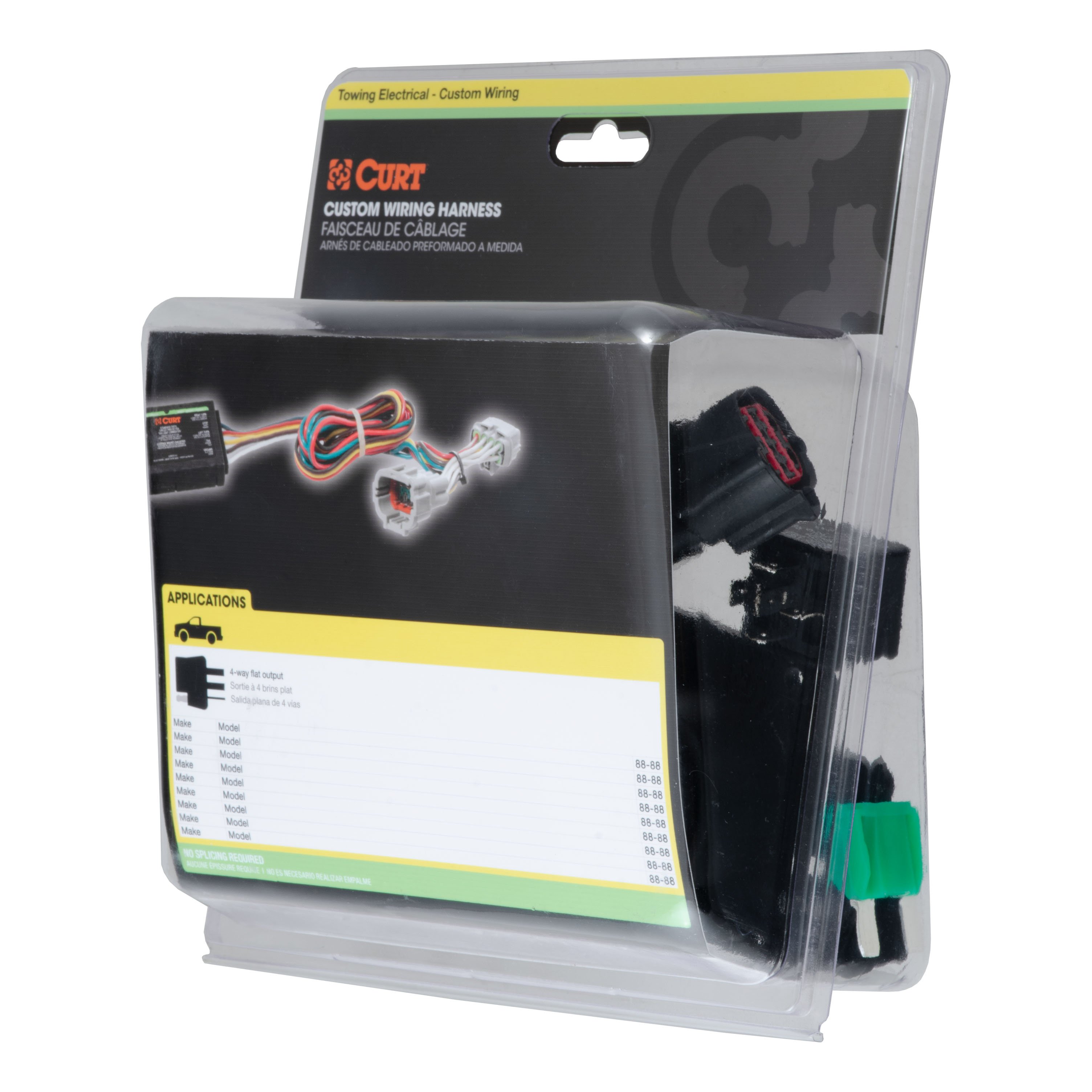
- Custom Wiring, 7-Way RV Blade Output (Plug & Play)
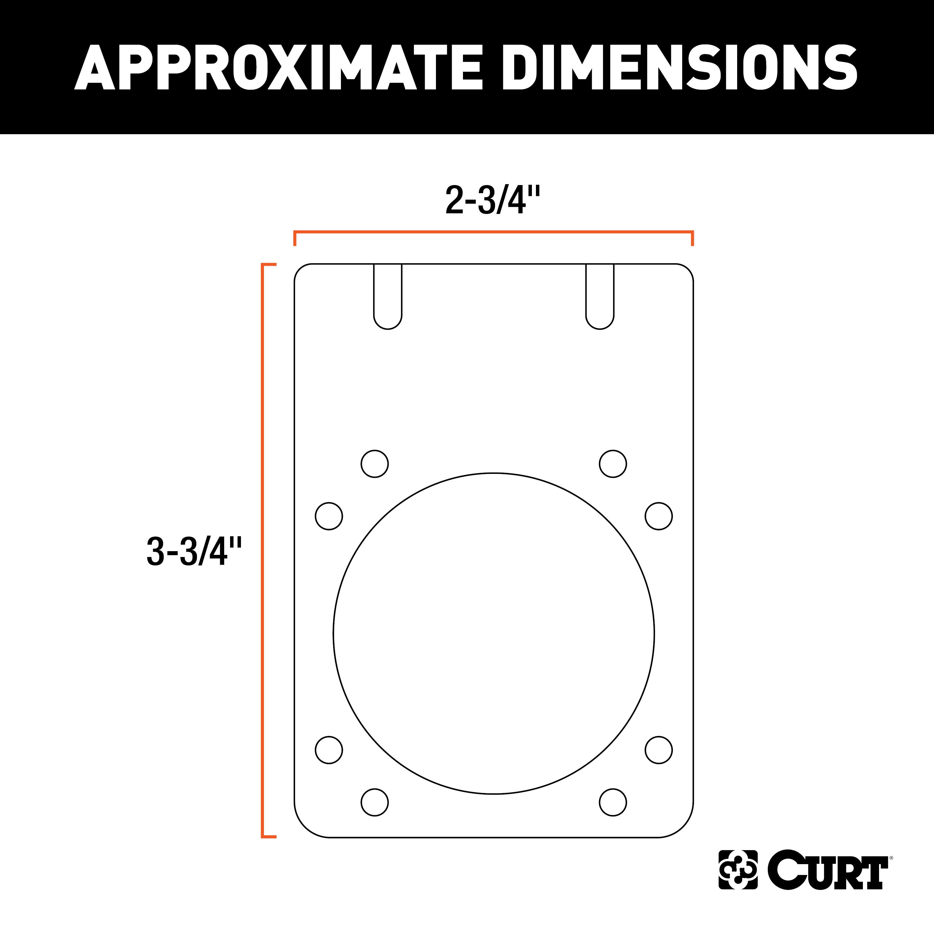
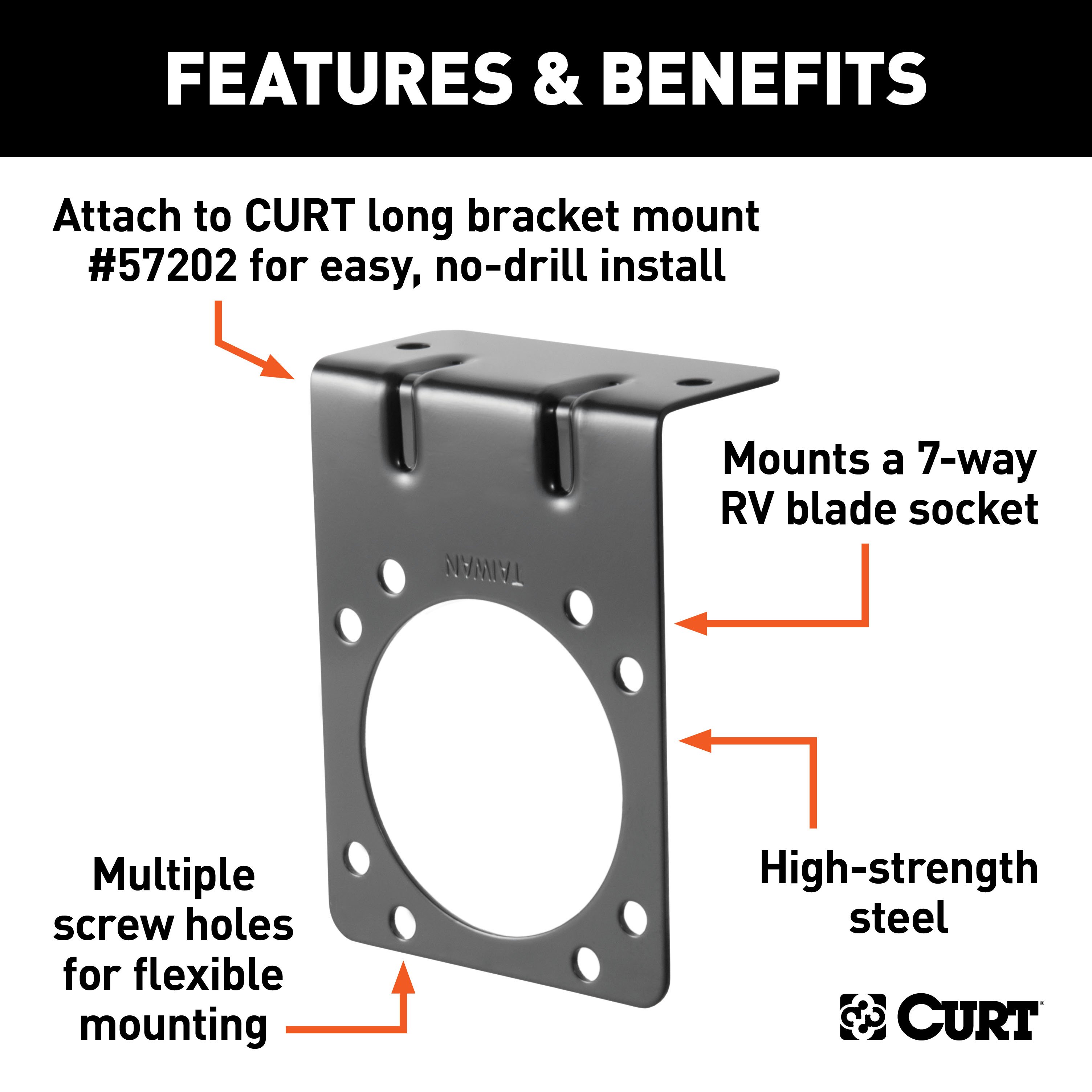
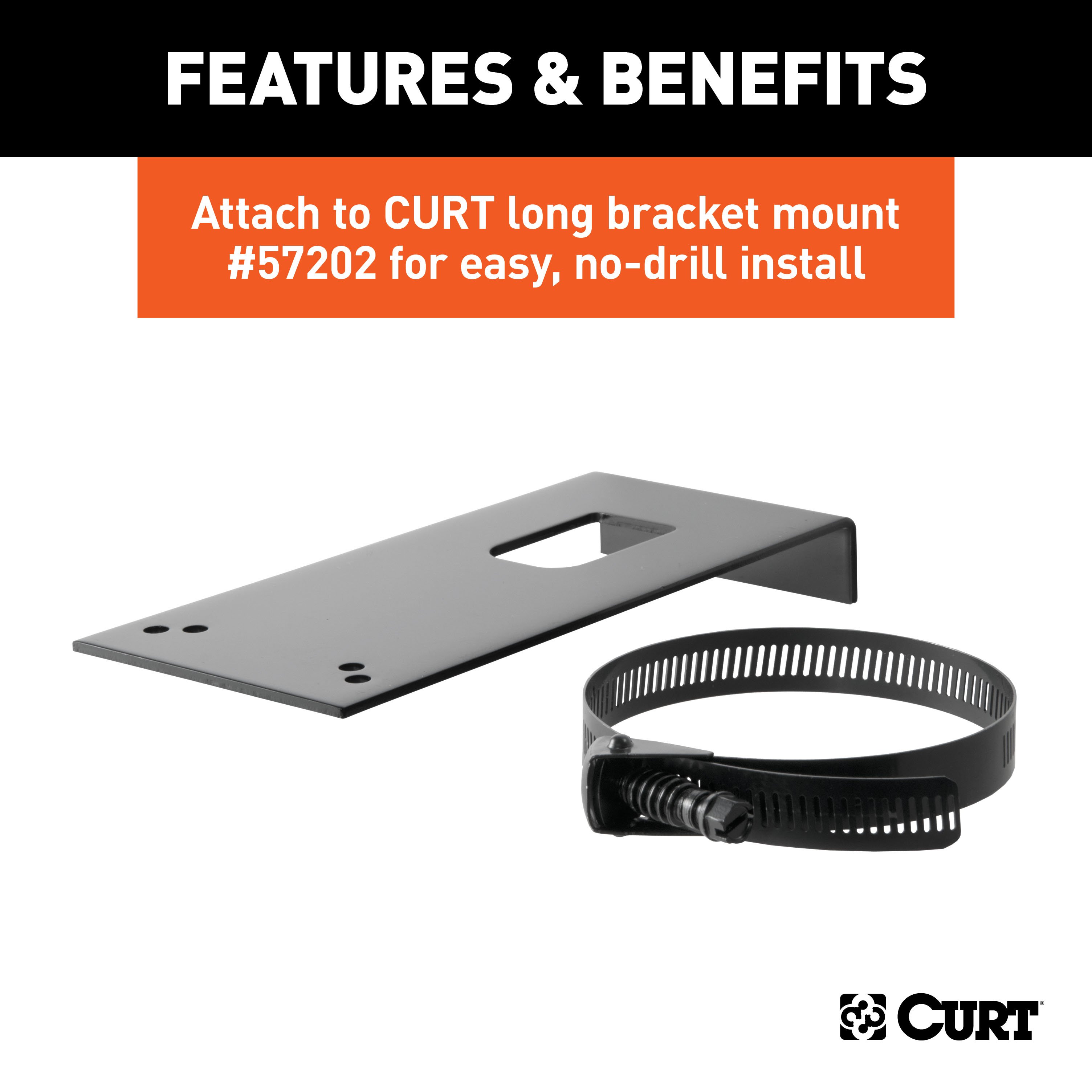
- Connector Mounting Bracket for 7-Way RV Blade (Black)
- Installation instructions, schematics, diagrams, and hardware (if required).
List of Fitment Years:
2011, 2012, 2013, 2014, 2015, 2016, 2017, 2018, 2019
CURT 56306 Vehicle-Side Custom RV Blade 7-Pin Trailer Wiring Harness
Manufactured by: Curt
CURT custom wiring is made with some of the most sophisticated technology in the industry and is designed to install with ease, giving you a long-lasting electrical connection for your towing setup If your vehicle is not equipped with wiring for towing a trailer, CURT custom wiring is the ideal solution A custom wiring harness (also called a T-connector) is a simple, plug-and-play electrical device that plugs into your vehicle's electrical system and provides a standard trailer wiring connection.
This is done using two or more vehicle-specific, OEM-compatible connectors to plug into the taillight assembly, eliminating the need for cutting, splicing and soldering during installation Custom wiring harnesses are made vehicle-specific, and while they are not available for all vehicles, they do offer one of the fastest, easiest and most secure ways to wire a vehicle for towing This particular harness provides a 7-way RV blade connector socket and is designed to be a custom wiring harness for certain years of the Ford Explorer and Police Interceptor Utility (see application info to verify fitment).
It comes with all necessary wiring components to establish a reliable trailer wiring connection, as well as a dust cover to keep the connector clean when not in use You have a picture in mind of your next destination -- maybe it's the boat landing at your favorite fishing spot, maybe it's a campsite that overlooks one of nature's masterpieces, or maybe it's the next big jobsite However, turning that picture into a reality takes more than just daydreaming.
It takes a solid connection and the right amount of power..
Features:
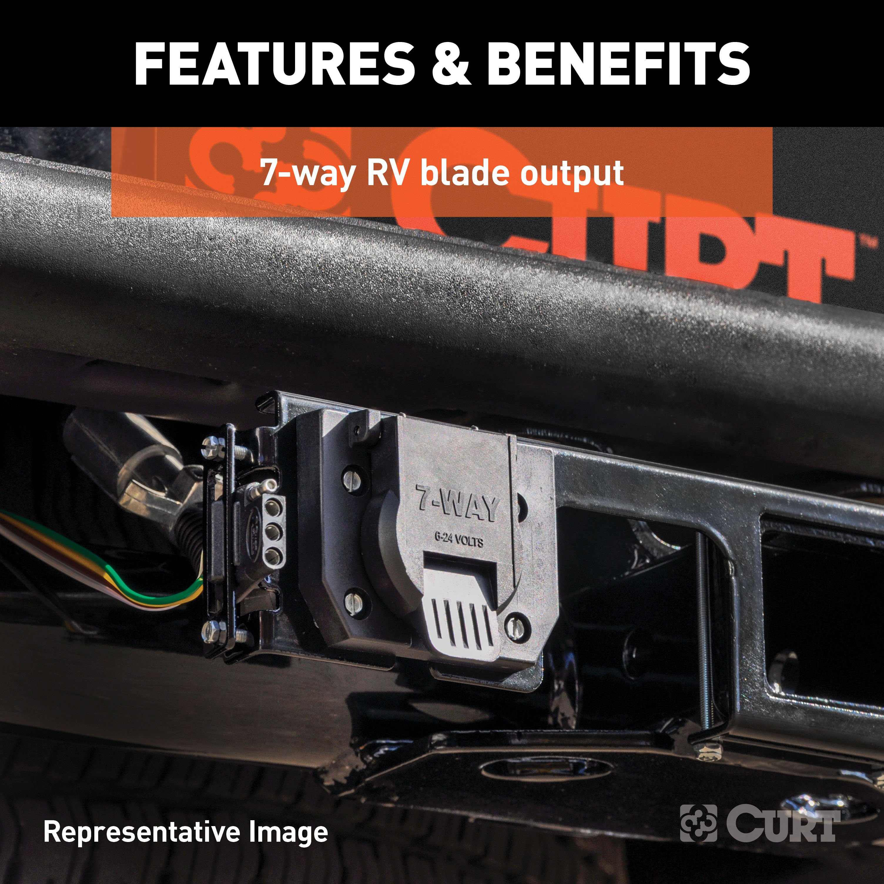
- Plugs into vehicle wiring assembly to provide a 7-way RV blade socket
- Simple plug-and-play design for less cutting and splicing
- 7-way connects tail, brake, reverse, turn signals, brakes and auxiliary power
- Spring-loaded dust cover keeps connector clean when not in use
- Slit loom keeps wires contained and well protected
- Backed by a limited one-year warranty
CURT 58290 Vehicle-Side Trailer Wiring Harness Mounting Bracket for 7-Way RV Blade
Manufactured by: Curt
CURT electrical connector brackets provide a simple solution for mounting wiring to your trailer hitch on the rear of your vehicle Connector wires can be a nuisance when they are just lying around They can get tangled up with cargo and even damaged.
An electrical connector left to hang off the back end of your vehicle is an even greater hazard Secure, protect and optimize the use of your electrical connector by mounting it with a CURT connector bracket This trailer wire connector bracket is designed to hold a 7-way RV blade socket.
It features sturdy steel construction with a black finish and can be mounted on your vehicle or trailer hitch When it comes to plugging in your trailer lights, it pays not to skimp out CURT electrical is the smart way to ensure that your trailer lights and electrical systems are prepared for the road ahead.
Keep the power flowing, no matter where your adventures take you, with quality electrical products from CURT..
Features:
- Securely mounts 7-way RV blade connector sockets
- Allows for attachment to the vehicle or trailer hitch
- Multiple screw holes offer flexible mounting options
- Constructed from high-strength steel
- Protected by a durable gloss black finish
Hitches Near Me: We operate out of several warehouses across the country, ensuring faster delivery to your location.
$90 99 $1,787.35 95% OFF
- Best Price on Web Guarantee
- Fastest Shipping
- FREE Shipping
- In Stock

We match lower prices from major authorized retailers for brand-new products in original packaging, provided the item is in stock. The competing seller must be an authorized, professional retail business; offers from
individuals, auctions, peer-to-peer sites, or unauthorized sellers don’t qualify. Used, refurbished, or open-box items are excluded.
Please see our full terms for details.
Verify Fitment
View products that fit your vehicle
Fits 's with the following styles:
View products that fit your vehicle
Fits 's with the following styles:
$1,787.35 $90 99
 Learn more
Questions? Call our Auto Experts at (877) 869-6690
Get it now, pay later
Select installments at checkout to split your purchase into 4 interest-free payments of $ every 2 weeks.
- No fees, ever.
- No impact on your credit score.
Payment options are offered by Affirm and are subject to an eligibility check and might not be available in all states. CA Residents: Loans by Affirm Loan Services, LLC are made or arranged pursuant to a California Finance Lender license.
Installments in partnership with


Each may be shipped from a separate location, and therefore, may arrive at different times
Product Details
- Brand: Curt
- Model: 56306 58290-CW1260
- Includes: Custom Wiring, Connector Mounting Bracket for 7-Way RV Blade Black)
Compatibility Chart
| Year Range | Make | Model | Style |
|---|
| Default | |
| Brand | Curt |
| Includes | 7-Way Mounting Bracket |
| Trailer Wiring Output Type | 7-Way Round |
| Trailer Wiring Install Style | Plug&Play |
Ask a Question about For 2011-2019 Ford Explorer Trailer Wiring 7 Way Trailer Wiring Plug w/ Bracket Fits All Models Curt
Be the first to ask a question.
| File | Size | |
|---|---|---|
| 56306_INS.pdf | 852.06KB | Download |
Description
This Wiring 7-Way + Bracket Fits The Following Vehicles:
2011 - 2019 Ford Explorer All Models
This Wiring 7-Way + Bracket Includes the Following Parts:
- Custom Wiring, 7-Way RV Blade Output (Plug & Play)
- Connector Mounting Bracket for 7-Way RV Blade (Black)
- Installation instructions, schematics, diagrams, and hardware (if required).
List of Fitment Years:
2011, 2012, 2013, 2014, 2015, 2016, 2017, 2018, 2019
CURT 56306 Vehicle-Side Custom RV Blade 7-Pin Trailer Wiring Harness
Manufactured by: Curt
CURT custom wiring is made with some of the most sophisticated technology in the industry and is designed to install with ease, giving you a long-lasting electrical connection for your towing setup If your vehicle is not equipped with wiring for towing a trailer, CURT custom wiring is the ideal solution A custom wiring harness (also called a T-connector) is a simple, plug-and-play electrical device that plugs into your vehicle's electrical system and provides a standard trailer wiring connection.
This is done using two or more vehicle-specific, OEM-compatible connectors to plug into the taillight assembly, eliminating the need for cutting, splicing and soldering during installation Custom wiring harnesses are made vehicle-specific, and while they are not available for all vehicles, they do offer one of the fastest, easiest and most secure ways to wire a vehicle for towing This particular harness provides a 7-way RV blade connector socket and is designed to be a custom wiring harness for certain years of the Ford Explorer and Police Interceptor Utility (see application info to verify fitment).
It comes with all necessary wiring components to establish a reliable trailer wiring connection, as well as a dust cover to keep the connector clean when not in use You have a picture in mind of your next destination -- maybe it's the boat landing at your favorite fishing spot, maybe it's a campsite that overlooks one of nature's masterpieces, or maybe it's the next big jobsite However, turning that picture into a reality takes more than just daydreaming.
It takes a solid connection and the right amount of power..
Features:
- Plugs into vehicle wiring assembly to provide a 7-way RV blade socket
- Simple plug-and-play design for less cutting and splicing
- 7-way connects tail, brake, reverse, turn signals, brakes and auxiliary power
- Spring-loaded dust cover keeps connector clean when not in use
- Slit loom keeps wires contained and well protected
- Backed by a limited one-year warranty
CURT 58290 Vehicle-Side Trailer Wiring Harness Mounting Bracket for 7-Way RV Blade
Manufactured by: Curt
CURT electrical connector brackets provide a simple solution for mounting wiring to your trailer hitch on the rear of your vehicle Connector wires can be a nuisance when they are just lying around They can get tangled up with cargo and even damaged.
An electrical connector left to hang off the back end of your vehicle is an even greater hazard Secure, protect and optimize the use of your electrical connector by mounting it with a CURT connector bracket This trailer wire connector bracket is designed to hold a 7-way RV blade socket.
It features sturdy steel construction with a black finish and can be mounted on your vehicle or trailer hitch When it comes to plugging in your trailer lights, it pays not to skimp out CURT electrical is the smart way to ensure that your trailer lights and electrical systems are prepared for the road ahead.
Keep the power flowing, no matter where your adventures take you, with quality electrical products from CURT..
Features:
- Securely mounts 7-way RV blade connector sockets
- Allows for attachment to the vehicle or trailer hitch
- Multiple screw holes offer flexible mounting options
- Constructed from high-strength steel
- Protected by a durable gloss black finish
Hitches Near Me: We operate out of several warehouses across the country, ensuring faster delivery to your location.


