




For 2002-2006 Honda CRV Trailer Wiring 7 Way Trailer Wiring Plug w/ Bracket Fits All Models Curt
Model: 55336 57672 51500 58361-CW2273This Wiring 7-Way + Bracket Fits The Following Vehicles:
2002 - 2006 Honda CR-V All Models
This Wiring 7-Way + Bracket Includes the Following Parts:
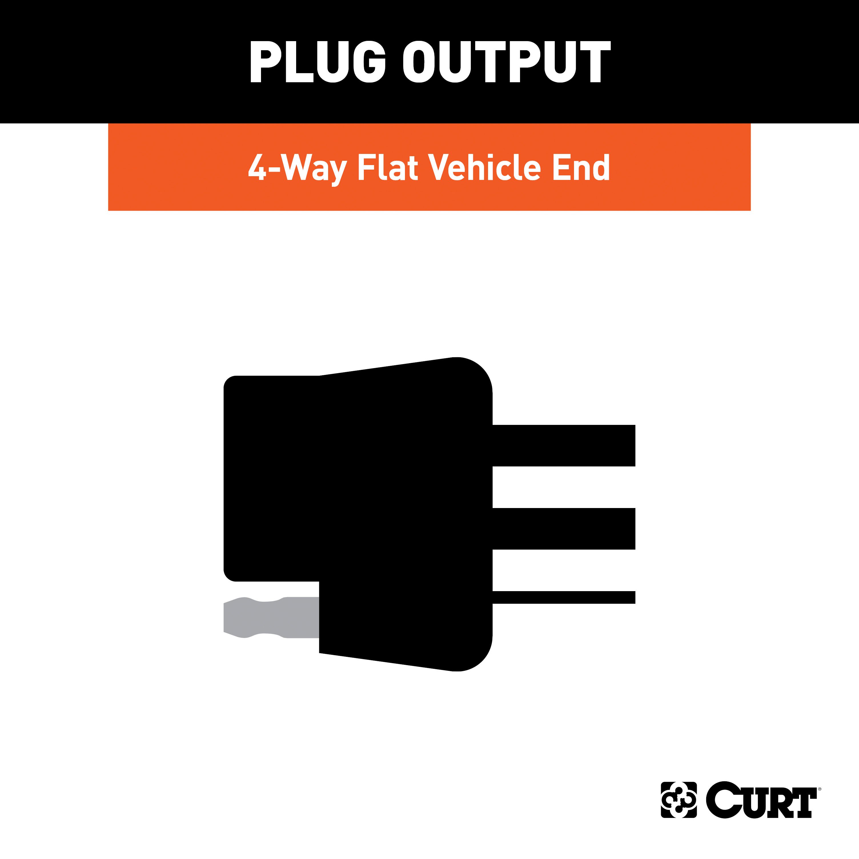
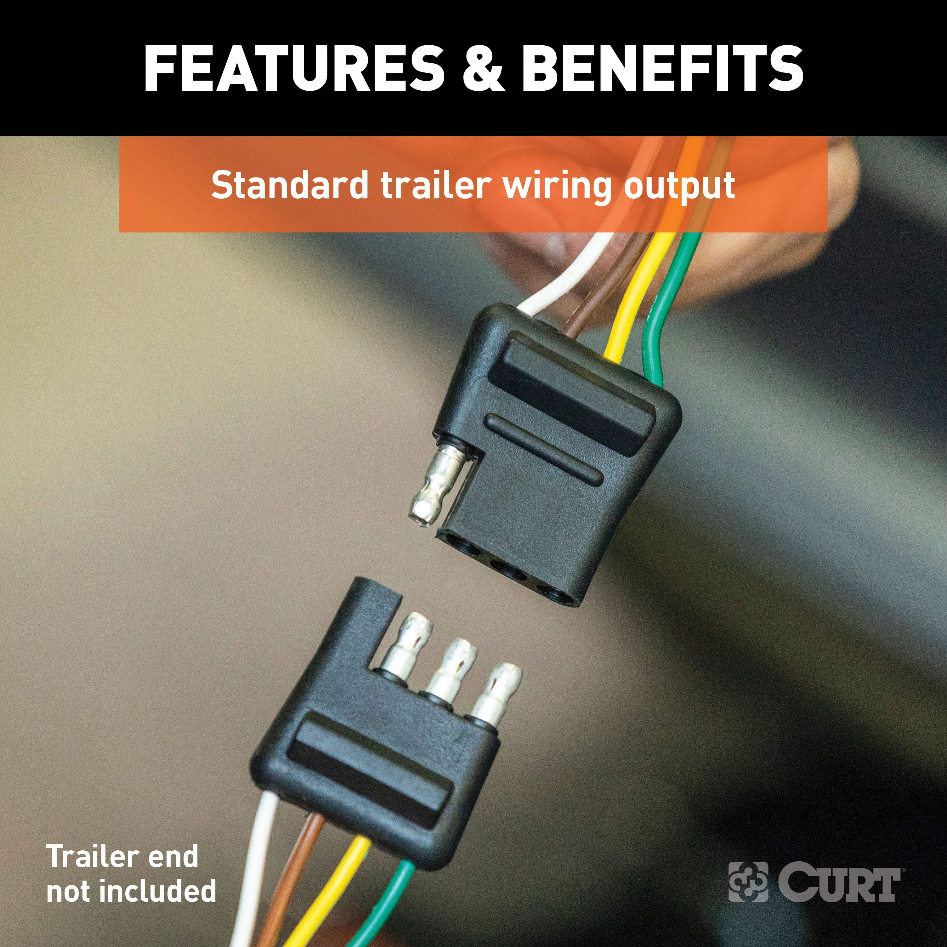
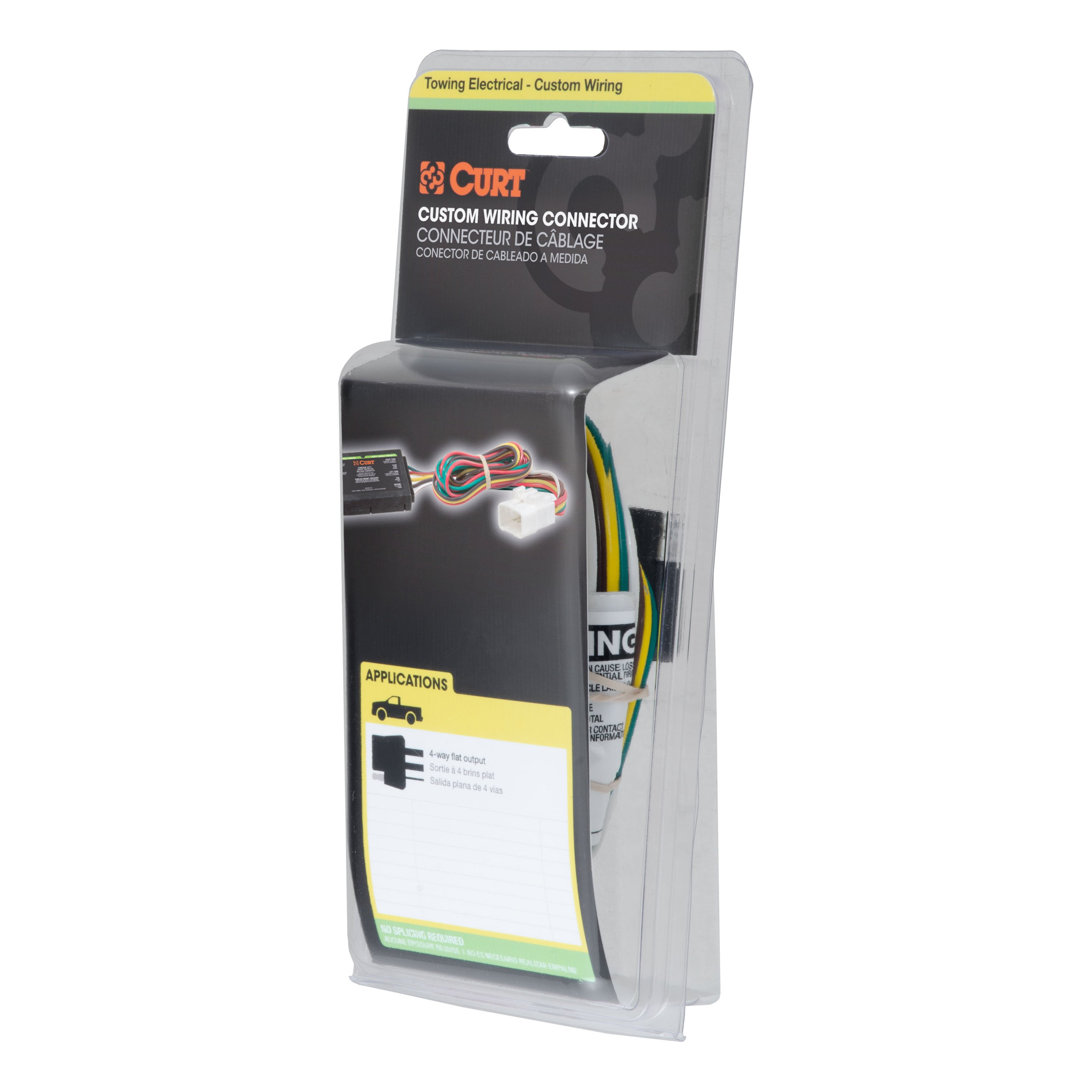
- Custom Wiring Connector, 4-Way Flat Output (Plug & Play)
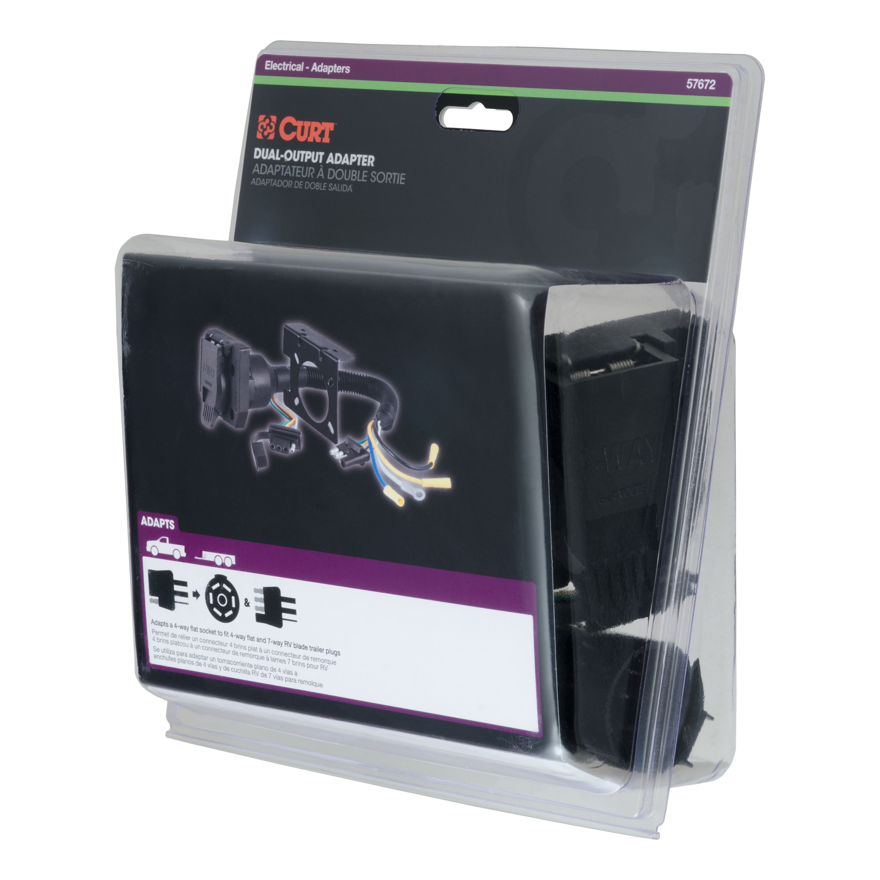
- Dual-Output Electrical Adapter (Adds 7-Way RV Blade to 4-Way Flat)
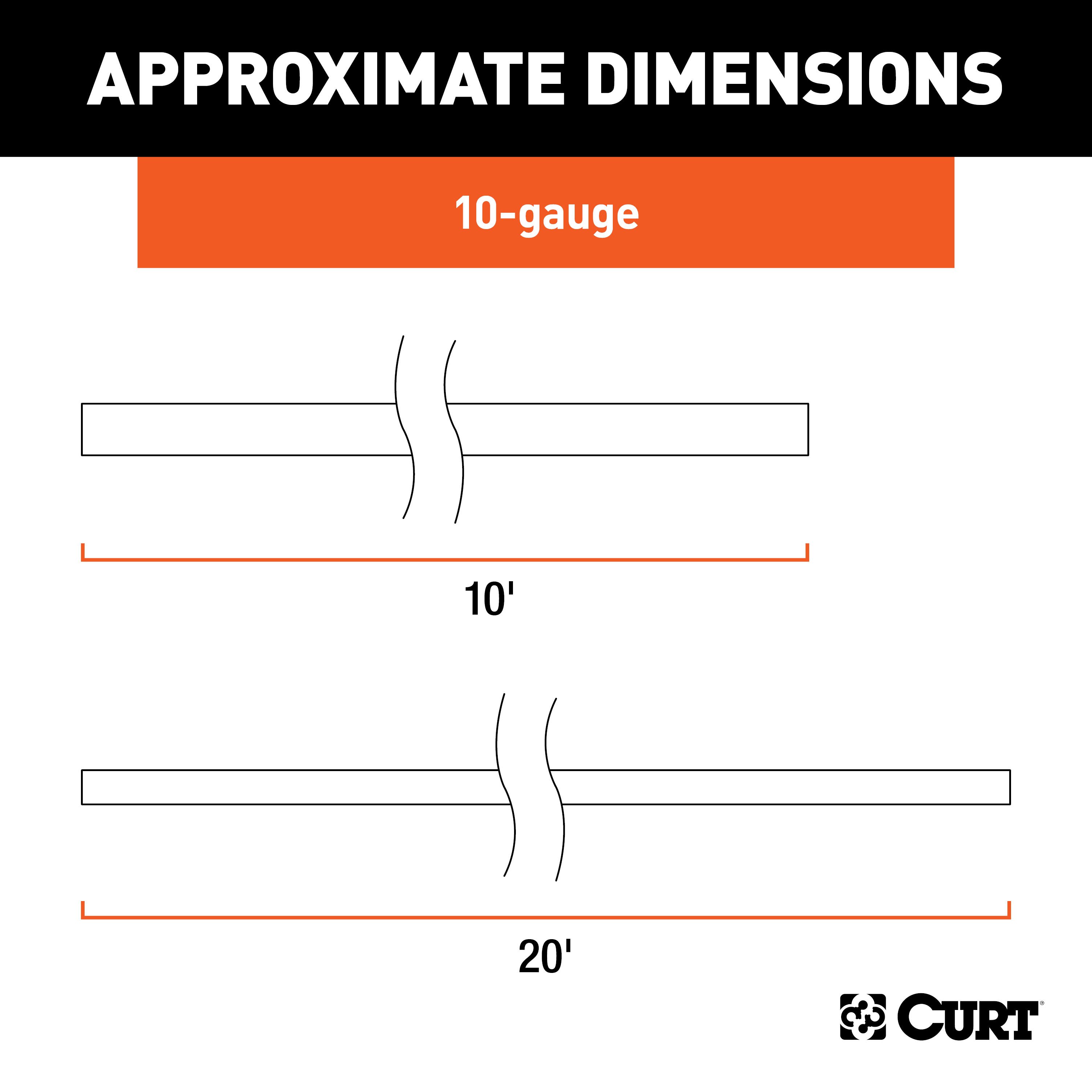
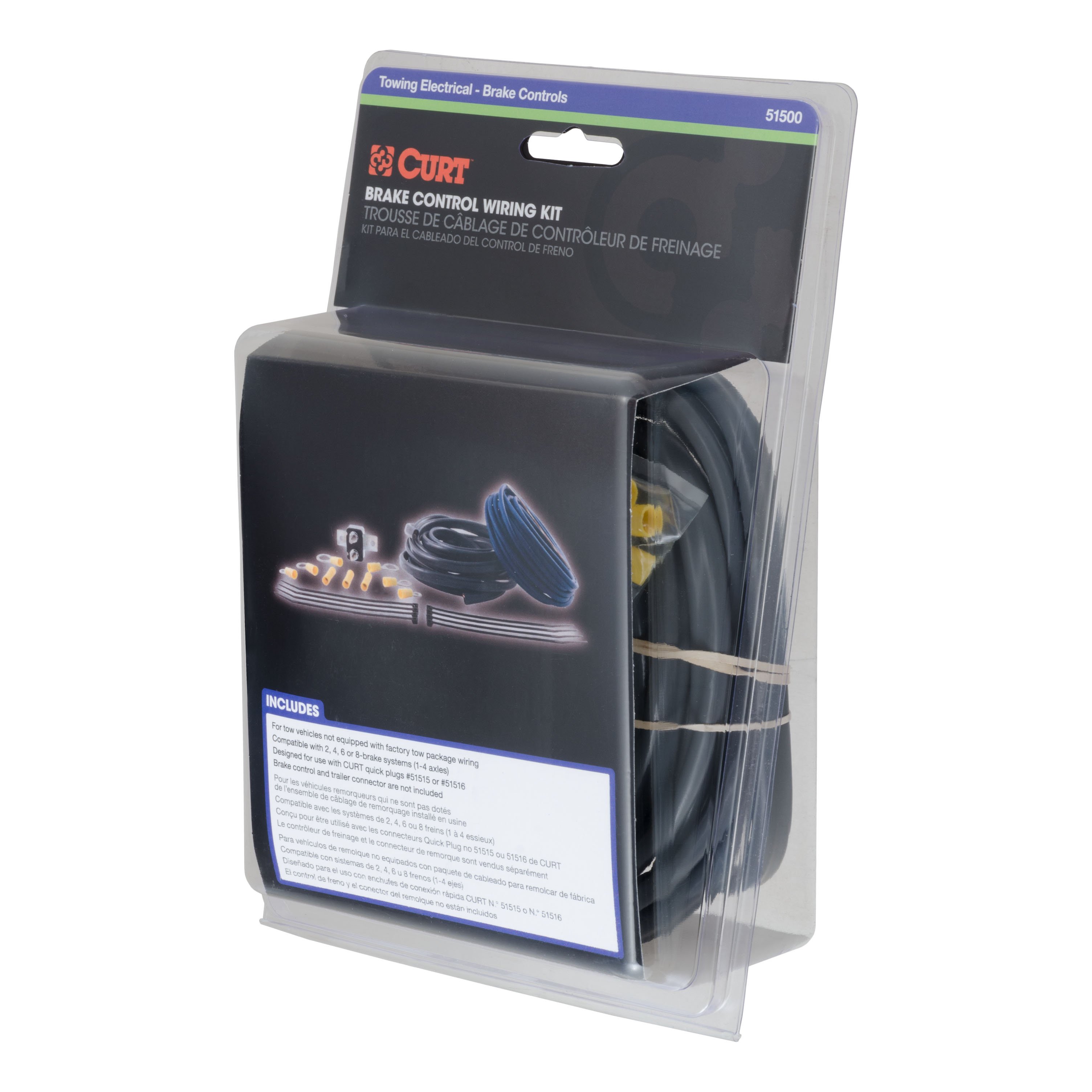
- Trailer Brake Controller Wiring Kit (duplex undercar wires, circuit breakers, terminals & ring connectors)
- 30-Amp Universal Circuit Breaker
- Installation instructions, schematics, diagrams, and hardware (if required).
List of Fitment Years:
2002, 2003, 2004, 2005, 2006
CURT 55336 Vehicle-Side Custom 4-Pin Trailer Wiring Harness
Manufactured by: Curt
CURT custom wiring connectors are the easiest way to outfit your vehicle with a CURT trailer wiring connection They are built with some of the most advanced technology in the industry, and each one is custom-fitted to work with a specific make and model Some automotive manufacturers install a special socket on the vehicle to be used for vehicle-to-trailer wiring.
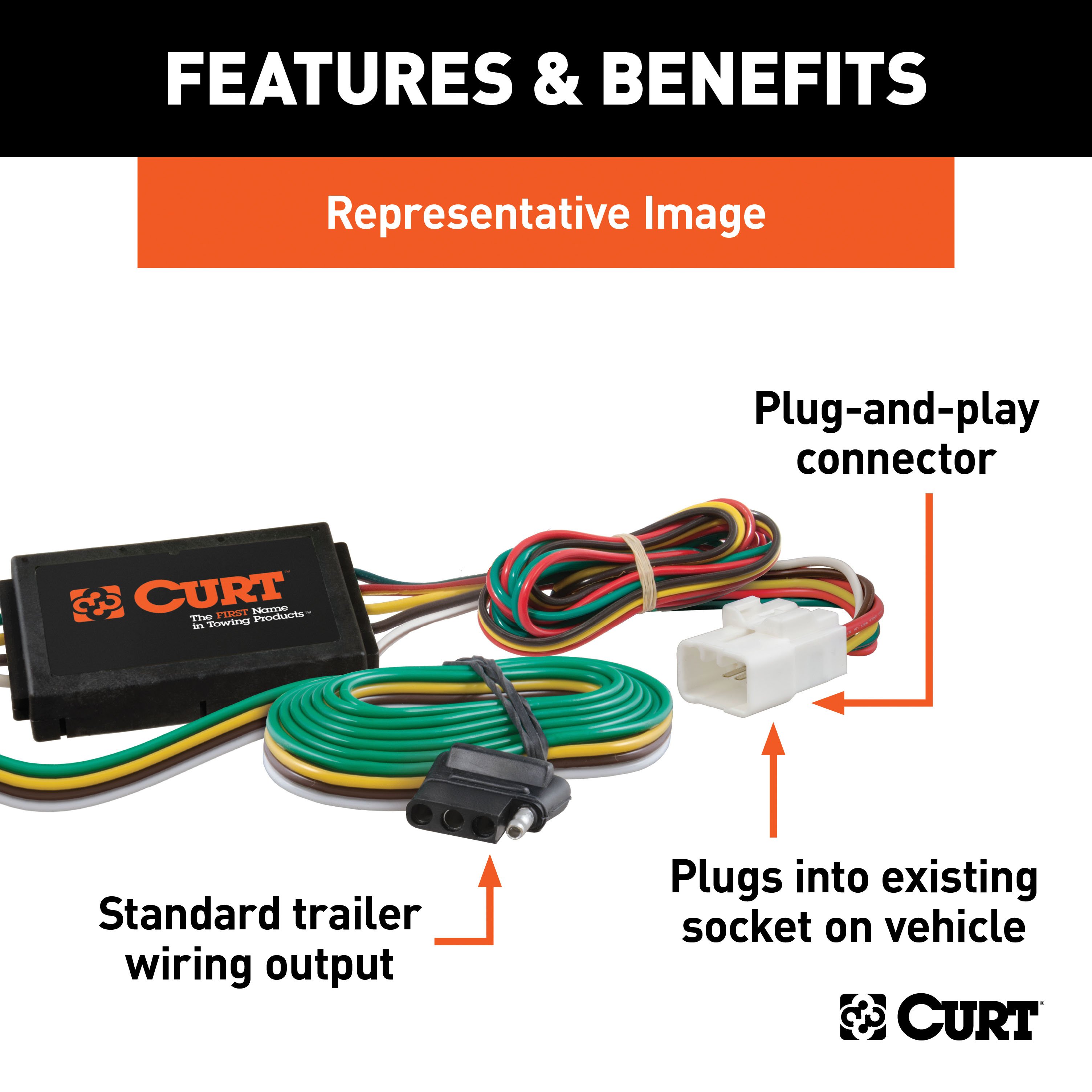
Although this special socket is not equipped on every vehicle, a CURT custom wiring connector -- also called a T-connector -- utilizes the socket for simple, stress-free installation Rather than requiring you to cut, splice and solder into your vehicle's wiring system, the custom wiring connector uses a single OEM-compatible plug and instantly provides a standard, universal vehicle-to-trailer wiring connection, typically in the form a 4-way flat All CURT custom wiring connectors are made vehicle-specific for the easiest possible installation and the best fit.
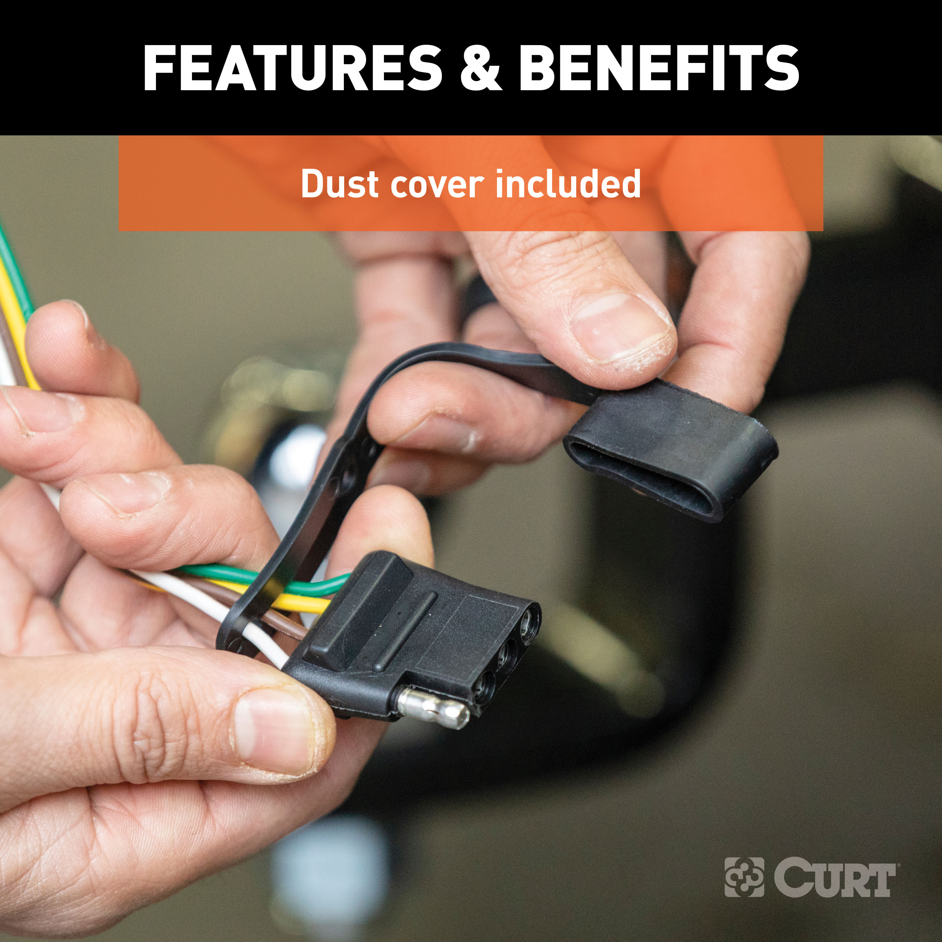
This particular plug-in connector provides a 4-way flat socket and is designed to be a custom wiring option for certain years of the Honda Accord, CRV, Element, Odyssey, Pilot and Prelude, Acura Integra, CL, RL, TL and MDX and Isuzu Oasis (to verify your vehicle compatibility, see application info) It comes with all necessary hardware to establish a solid connection It also comes with a dust cover to keep the connector socket clean when not in use.
To ensure long-lasting reliability, all CURT custom wiring connectors are thoroughly tested for optimal functionality Stress is the last thing you should feel when towing a trailer -- whether you're hauling your RV to that favorite camping destination, your ATVs up to the hunting grounds or your fishing boat to the new hidden hotspot At CURT, we think your towing equipment should add to the enjoyment of your experience, not detract from it..
Features:
- Plugs into existing OEM vehicle socket to provide a 4-way flat socket
- Simple plug-and-play design eliminates the need for cutting or splicing
- 4-way flat output connects tail lights, brake lights and turn signals
- Equipped with tail light converter for vehicle-trailer compatibility
- Constructed with SMT circuitry for better performance and durability
- Dust cover included to keep connector clean when not in use
- Backed by a limited one-year warranty
CURT 57672 Dual-Output 4-Way Flat Vehicle-Side to 7-Way RV Blade Trailer Wiring Adapter
Manufactured by: Curt
There are several different types of connectors used to supply power from a tow vehicle's electrical system to a trailer's wiring system Some trailers only need the bare essentials -- running lights, brake lights and turn signals -- while others require a connection for reverse lights, electric brakes and auxiliary power With connectors ranging from simple to complex, it may be the case that the connection between your vehicle and your trailer is not a perfect match.
For example, your truck may be equipped with a 6-way round socket, but your trailer may have a 4-way flat plug For this very common problem, CURT offers a quick and simple solution in the form of an electrical adapter An adapter is an electrical device that allows a connection to be made between a mismatched trailer plug and vehicle socket.
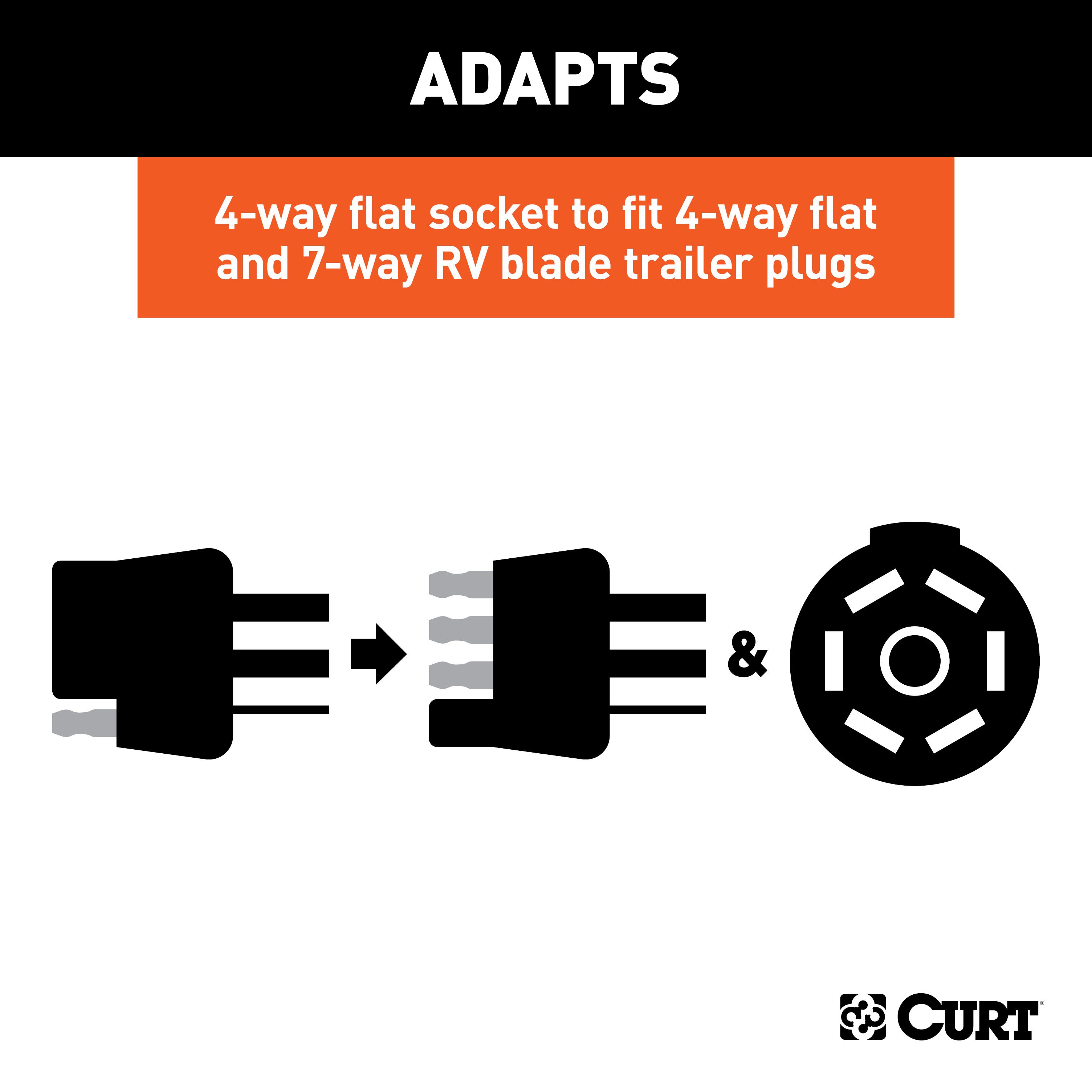
It easily plugs in your vehicle's electrical socket and usually requires no additional wiring CURT offers an array of adapters to accommodate most types of plugs and sockets, including 4-way flat, 4-way round, 5-way flat, 6-way round, 7-way RV blades and more This special dual-output electrical adapter is actually designed to adapt a 4-way flat vehicle socket to fit multiple trailer plugs, including a 4-way flat and a 7-way RV blade connector.
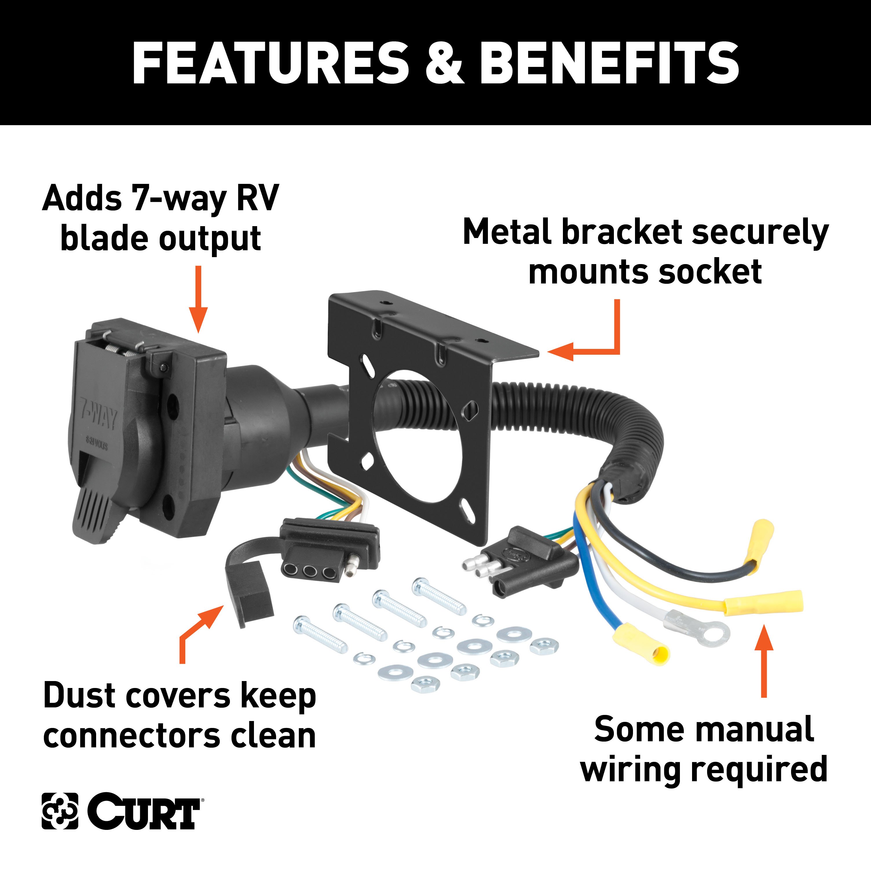
Some manual wiring is required This multipurpose socket also comes with dust covers, a mounting bracket and all necessary mounting hardware for a complete installation All CURT wiring and electrical products come with a one-year limited warranty to give you the assurance you need to tow with confidence..
Features:
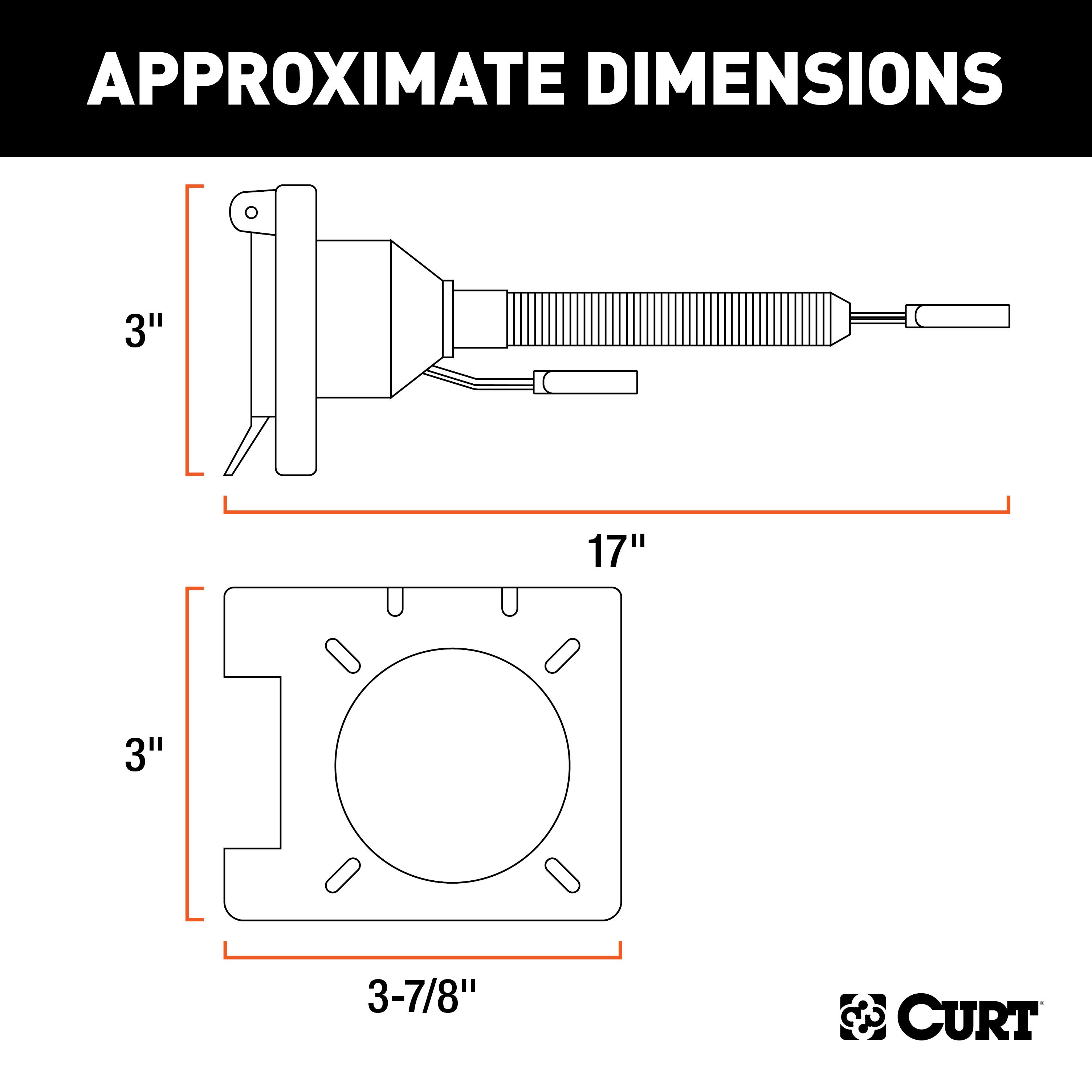
- Adapts a 4-way flat socket to fit 4-way flat and 7-way RV blade trailer plugs
- 4-way flat output connects tail lights, brake lights and turn signals
- 7-way connects tail, brake, reverse, turn signals, brakes and auxiliary power
- Dust covers included to keep connectors clean when not in use
- Slit loom keeps wires contained and well protected
- Metal bracket securely mounts wiring to the vehicle or trailer hitch
CURT 51500 Electric Trailer Brake Controller Wiring Kit
Manufactured by: Curt
It takes a lot of power to stop a moving trailer, especially when that trailer is hauling livestock, construction materials, industrial equipment or other heavy-duty cargo Play it safe when you tow and give your trailer brakes the control they need with a CURT trailer brake controller and brake controller harness This brake controller wiring kit is designed for vehicles that do not have an included towing prep package.
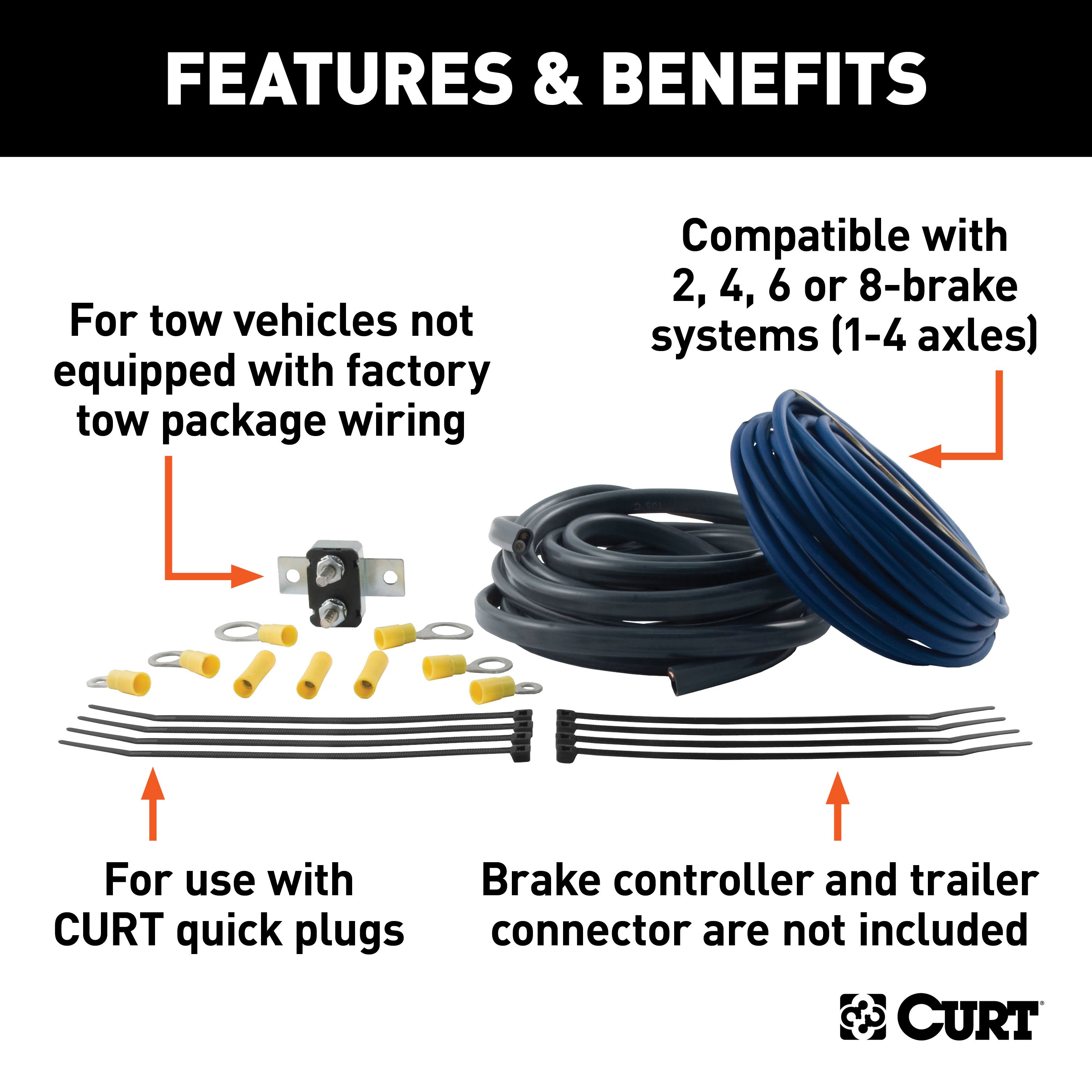
It includes cables, ring terminals, cable ties and a circuit breaker to splice into your vehicle's wiring system and allow installation of a CURT trailer brake controller This wiring kit is compatible with systems with up to eight brakes..
Features:
- For tow vehicles not equipped with factory tow package wiring
- Compatible with 2, 4, 6 or 8-brake systems (1-4 axles)
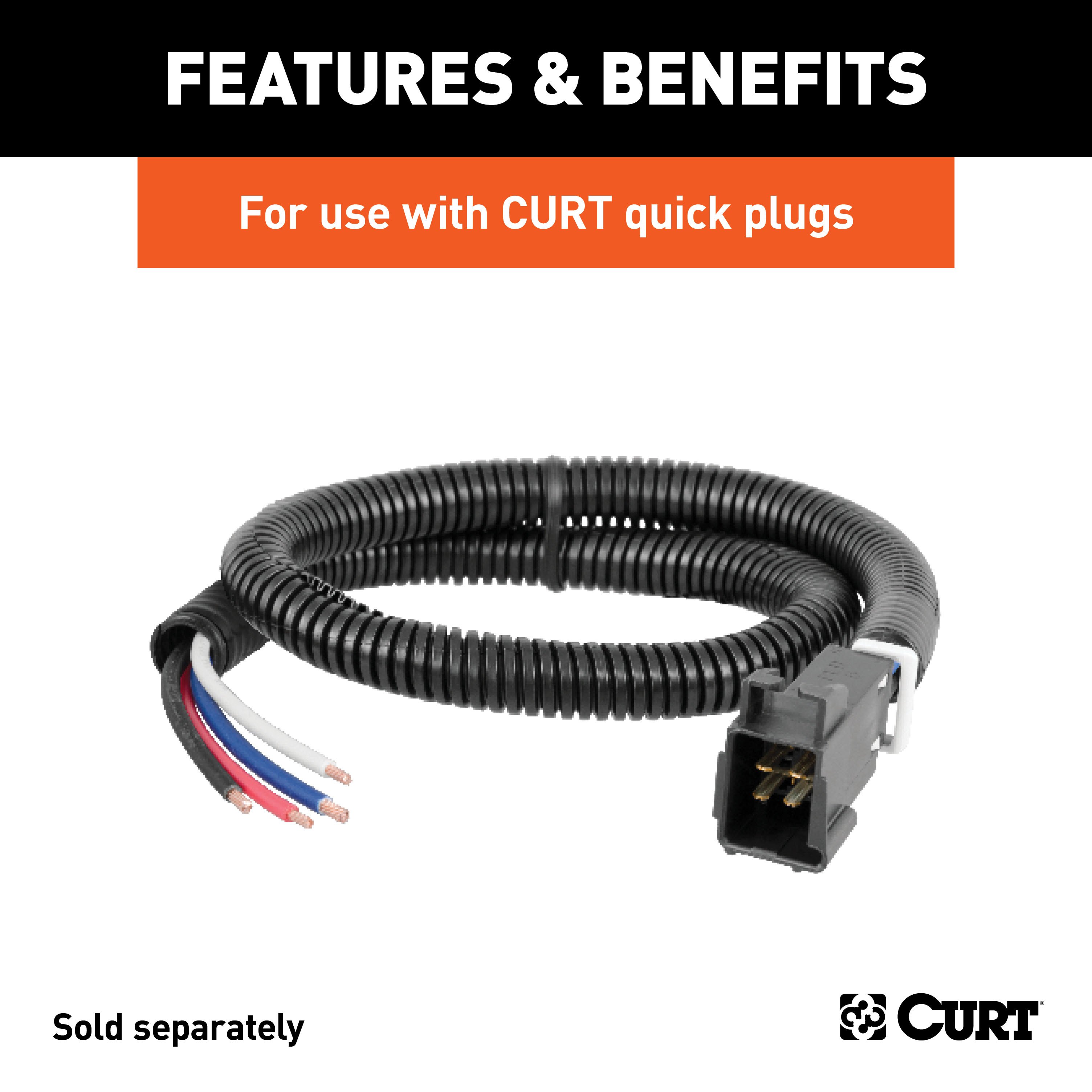
- Designed for use with CURT quick plugs #51515 or #51516
- Brake controller and trailer connector are not included
CURT 58361 30-Amp Universal Circuit Breaker
Manufactured by: Curt
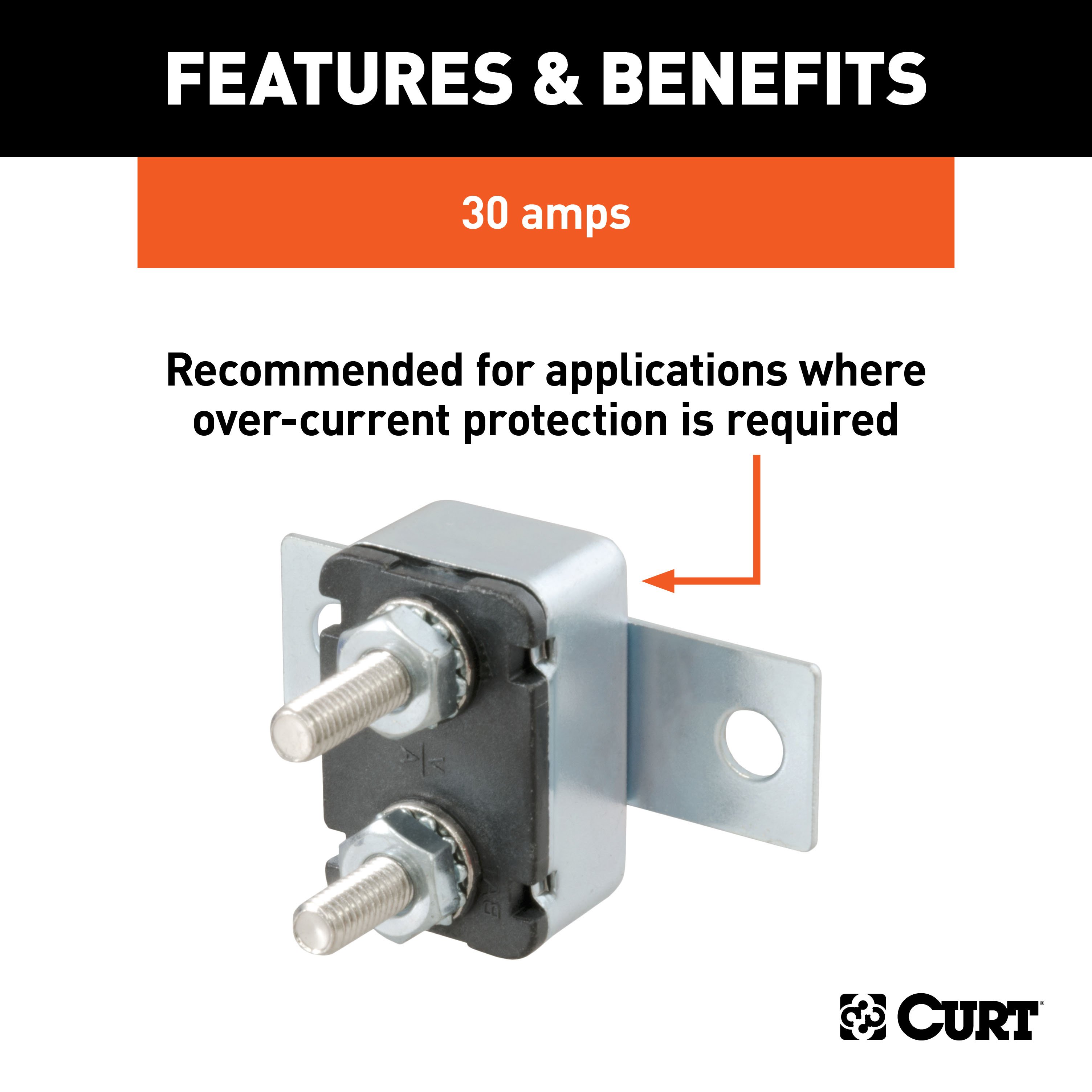
Whether you're a contractor on your way to the jobsite or just a casual fisherman heading to the boat landing, you need working trailer lights to tow safely and legally For any towing setup, CURT offers quality wiring components, including complete wiring kits, circuit breakers, wiring connectors and more This universal circuit breaker is rated for 30 amps and recommended for applications where over-current protection is required..
Features:
- Recommended for applications where over-current protection is required
Hitches Near Me: We operate out of several warehouses across the country, ensuring faster delivery to your location.
$125 99 $155.80 19% OFF
- Best Price on Web Guarantee
- Fastest Shipping
- FREE Shipping
- In Stock

We match lower prices from major authorized retailers for brand-new products in original packaging, provided the item is in stock. The competing seller must be an authorized, professional retail business; offers from
individuals, auctions, peer-to-peer sites, or unauthorized sellers don’t qualify. Used, refurbished, or open-box items are excluded.
Please see our full terms for details.
Verify Fitment
View products that fit your vehicle
Fits 's with the following styles:
View products that fit your vehicle
Fits 's with the following styles:
$155.80 $125 99
 Learn more
Questions? Call our Auto Experts at (877) 869-6690
Get it now, pay later
Select installments at checkout to split your purchase into 4 interest-free payments of $ every 2 weeks.
- No fees, ever.
- No impact on your credit score.
Payment options are offered by Affirm and are subject to an eligibility check and might not be available in all states. CA Residents: Loans by Affirm Loan Services, LLC are made or arranged pursuant to a California Finance Lender license.
Installments in partnership with

Product Details
- Brand: Curt
- Model: 55336 57672 51500 58361-CW2273
- Includes: Custom Wiring Connector, Dual-Output Electrical Adapter, Trailer Brake Controller Wiring Kit, 30-Amp Universal Circuit Breaker
Compatibility Chart
| Year Range | Make | Model | Style |
|---|
This Wiring 7-Way + Bracket Fits The Following Vehicles:
2002 - 2006 Honda CR-V All Models
This Wiring 7-Way + Bracket Includes the Following Parts:
- Custom Wiring Connector, 4-Way Flat Output (Plug & Play)
- Dual-Output Electrical Adapter (Adds 7-Way RV Blade to 4-Way Flat)
- Trailer Brake Controller Wiring Kit (duplex undercar wires, circuit breakers, terminals & ring connectors)
- 30-Amp Universal Circuit Breaker
- Installation instructions, schematics, diagrams, and hardware (if required).
List of Fitment Years:
2002, 2003, 2004, 2005, 2006
CURT 55336 Vehicle-Side Custom 4-Pin Trailer Wiring Harness
Manufactured by: Curt
CURT custom wiring connectors are the easiest way to outfit your vehicle with a CURT trailer wiring connection They are built with some of the most advanced technology in the industry, and each one is custom-fitted to work with a specific make and model Some automotive manufacturers install a special socket on the vehicle to be used for vehicle-to-trailer wiring.
Although this special socket is not equipped on every vehicle, a CURT custom wiring connector -- also called a T-connector -- utilizes the socket for simple, stress-free installation Rather than requiring you to cut, splice and solder into your vehicle's wiring system, the custom wiring connector uses a single OEM-compatible plug and instantly provides a standard, universal vehicle-to-trailer wiring connection, typically in the form a 4-way flat All CURT custom wiring connectors are made vehicle-specific for the easiest possible installation and the best fit.
This particular plug-in connector provides a 4-way flat socket and is designed to be a custom wiring option for certain years of the Honda Accord, CRV, Element, Odyssey, Pilot and Prelude, Acura Integra, CL, RL, TL and MDX and Isuzu Oasis (to verify your vehicle compatibility, see application info) It comes with all necessary hardware to establish a solid connection It also comes with a dust cover to keep the connector socket clean when not in use.
To ensure long-lasting reliability, all CURT custom wiring connectors are thoroughly tested for optimal functionality Stress is the last thing you should feel when towing a trailer -- whether you're hauling your RV to that favorite camping destination, your ATVs up to the hunting grounds or your fishing boat to the new hidden hotspot At CURT, we think your towing equipment should add to the enjoyment of your experience, not detract from it..
Features:
- Plugs into existing OEM vehicle socket to provide a 4-way flat socket
- Simple plug-and-play design eliminates the need for cutting or splicing
- 4-way flat output connects tail lights, brake lights and turn signals
- Equipped with tail light converter for vehicle-trailer compatibility
- Constructed with SMT circuitry for better performance and durability
- Dust cover included to keep connector clean when not in use
- Backed by a limited one-year warranty
CURT 57672 Dual-Output 4-Way Flat Vehicle-Side to 7-Way RV Blade Trailer Wiring Adapter
Manufactured by: Curt
There are several different types of connectors used to supply power from a tow vehicle's electrical system to a trailer's wiring system Some trailers only need the bare essentials -- running lights, brake lights and turn signals -- while others require a connection for reverse lights, electric brakes and auxiliary power With connectors ranging from simple to complex, it may be the case that the connection between your vehicle and your trailer is not a perfect match.
For example, your truck may be equipped with a 6-way round socket, but your trailer may have a 4-way flat plug For this very common problem, CURT offers a quick and simple solution in the form of an electrical adapter An adapter is an electrical device that allows a connection to be made between a mismatched trailer plug and vehicle socket.
It easily plugs in your vehicle's electrical socket and usually requires no additional wiring CURT offers an array of adapters to accommodate most types of plugs and sockets, including 4-way flat, 4-way round, 5-way flat, 6-way round, 7-way RV blades and more This special dual-output electrical adapter is actually designed to adapt a 4-way flat vehicle socket to fit multiple trailer plugs, including a 4-way flat and a 7-way RV blade connector.
Some manual wiring is required This multipurpose socket also comes with dust covers, a mounting bracket and all necessary mounting hardware for a complete installation All CURT wiring and electrical products come with a one-year limited warranty to give you the assurance you need to tow with confidence..
Features:
- Adapts a 4-way flat socket to fit 4-way flat and 7-way RV blade trailer plugs
- 4-way flat output connects tail lights, brake lights and turn signals
- 7-way connects tail, brake, reverse, turn signals, brakes and auxiliary power
- Dust covers included to keep connectors clean when not in use
- Slit loom keeps wires contained and well protected
- Metal bracket securely mounts wiring to the vehicle or trailer hitch
CURT 51500 Electric Trailer Brake Controller Wiring Kit
Manufactured by: Curt
It takes a lot of power to stop a moving trailer, especially when that trailer is hauling livestock, construction materials, industrial equipment or other heavy-duty cargo Play it safe when you tow and give your trailer brakes the control they need with a CURT trailer brake controller and brake controller harness This brake controller wiring kit is designed for vehicles that do not have an included towing prep package.
It includes cables, ring terminals, cable ties and a circuit breaker to splice into your vehicle's wiring system and allow installation of a CURT trailer brake controller This wiring kit is compatible with systems with up to eight brakes..
Features:
- For tow vehicles not equipped with factory tow package wiring
- Compatible with 2, 4, 6 or 8-brake systems (1-4 axles)
- Designed for use with CURT quick plugs #51515 or #51516
- Brake controller and trailer connector are not included
CURT 58361 30-Amp Universal Circuit Breaker
Manufactured by: Curt
Whether you're a contractor on your way to the jobsite or just a casual fisherman heading to the boat landing, you need working trailer lights to tow safely and legally For any towing setup, CURT offers quality wiring components, including complete wiring kits, circuit breakers, wiring connectors and more This universal circuit breaker is rated for 30 amps and recommended for applications where over-current protection is required..
Features:
- Recommended for applications where over-current protection is required
Hitches Near Me: We operate out of several warehouses across the country, ensuring faster delivery to your location.
| Default | |
| UPC | 612314553365 |
| ['Part Number | 55336 |
| Item Weight | 0.700 |
| Electrical System Type | 3W |
| Tail Light Circuits | 7.5 Amps |
| Warranty | One-Year Limited Warranty |
| Turn and Brake Circuits | |
| 3.0 Amps', 'Part Number | 57672 |
| UPC | 612314047048 |
| Item Weight | 1.240 |
| Warranty | One-Year Limited Warranty |
| Note 1 | |
| Some manual wiring required', 'Part Number | 51500 |
| UPC | 612314511501, 612314043378 |
| Item Weight | 2.025, 0.080 |
| Warranty | One-Year Limited Warranty |
| Includes 10 gauge duplex wire, 10 gauge cross-linked wire, 30-am | 58361 |
| Warranty | |
| One-Year Limited Warranty', 'Output Type | 7-Way Round Plug', 'Approx Installation Time (Minutes):50', 'Installation Difficulty:Novice'] |
Ask a Question about For 2002-2006 Honda CRV Trailer Wiring 7 Way Trailer Wiring Plug w/ Bracket Fits All Models Curt
Be the first to ask a question.


