





For 2017-2024 Ford F450 Super Duty Trailer Hitch + Wiring 4 Pin Fits Cab & Chassis w/ 34" Frame Curt 15445 58044 2 inch Tow Receiver
Model: 15445 58044-CH1674This Trailer Tow Hitch + 4-Flat Fits The Following Vehicles:
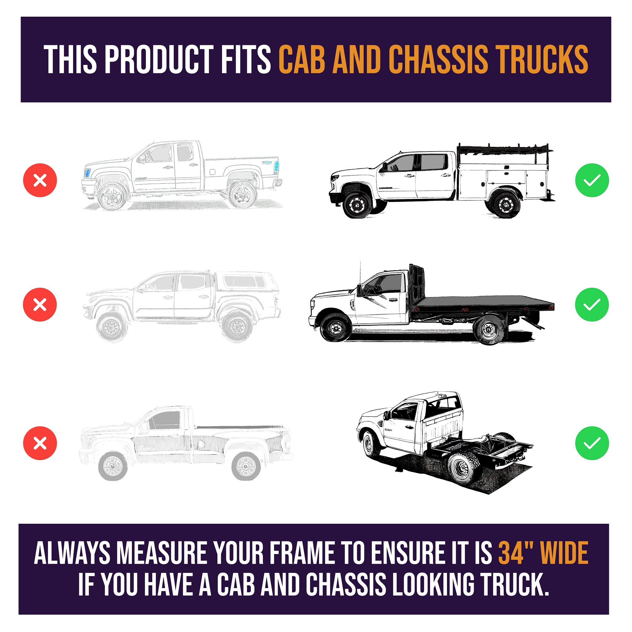
2017 - 2024 Ford F-450 Super Duty Cab & Chassis w/ 34" Frame
This Trailer Tow Hitch + 4-Flat Includes the Following Parts:
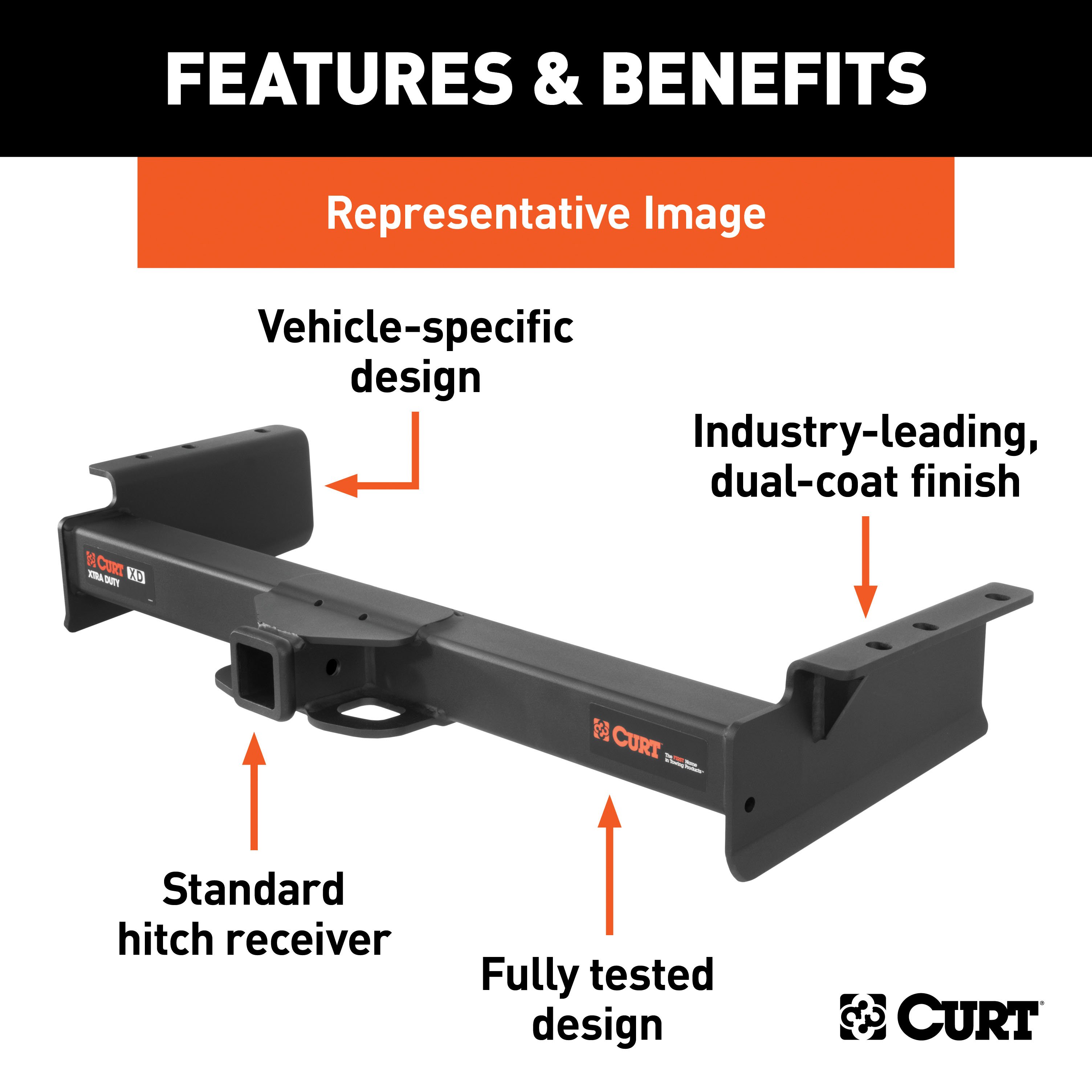
- Xtra Duty Class 5 Trailer Hitch, 2" Receiver (Drilling Required)
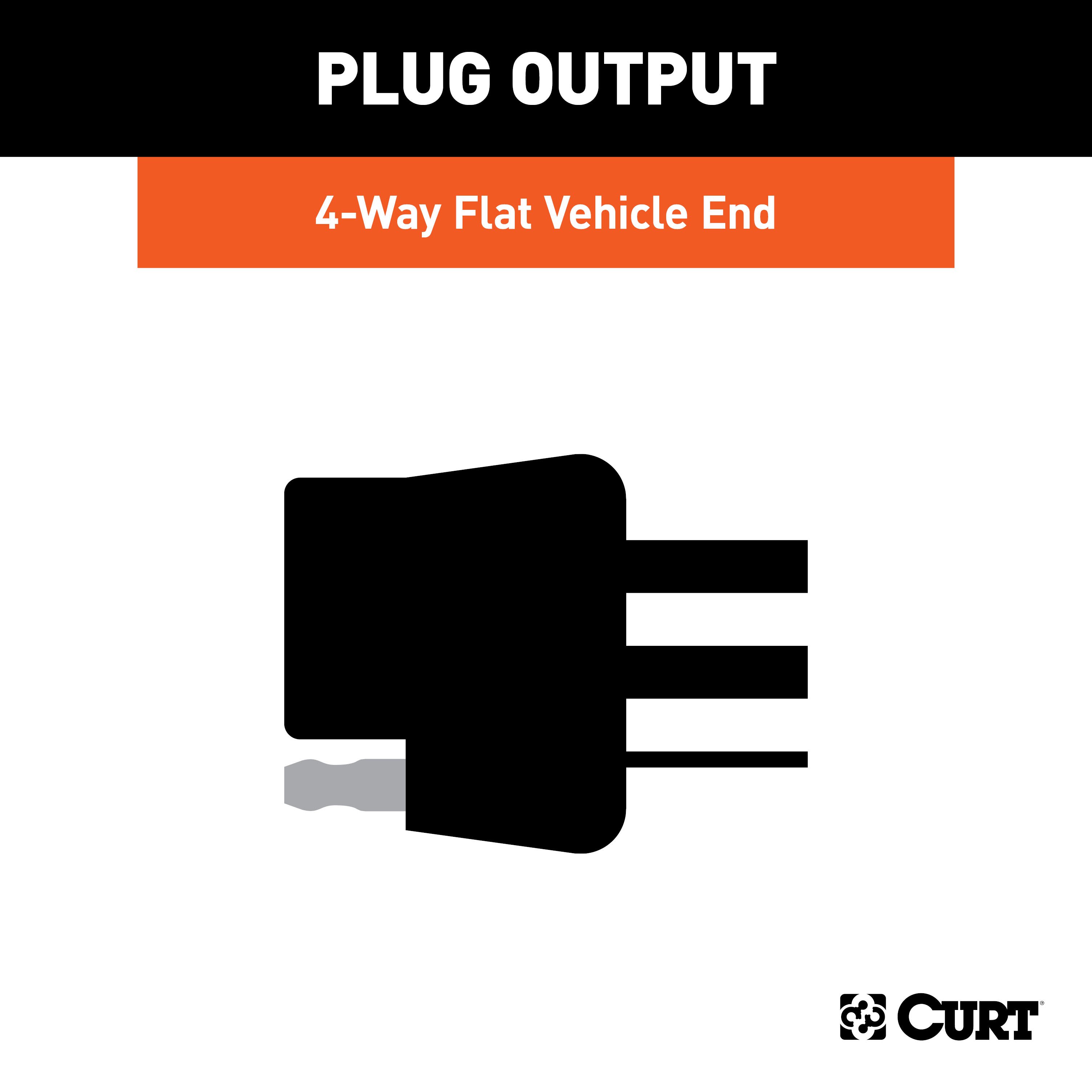
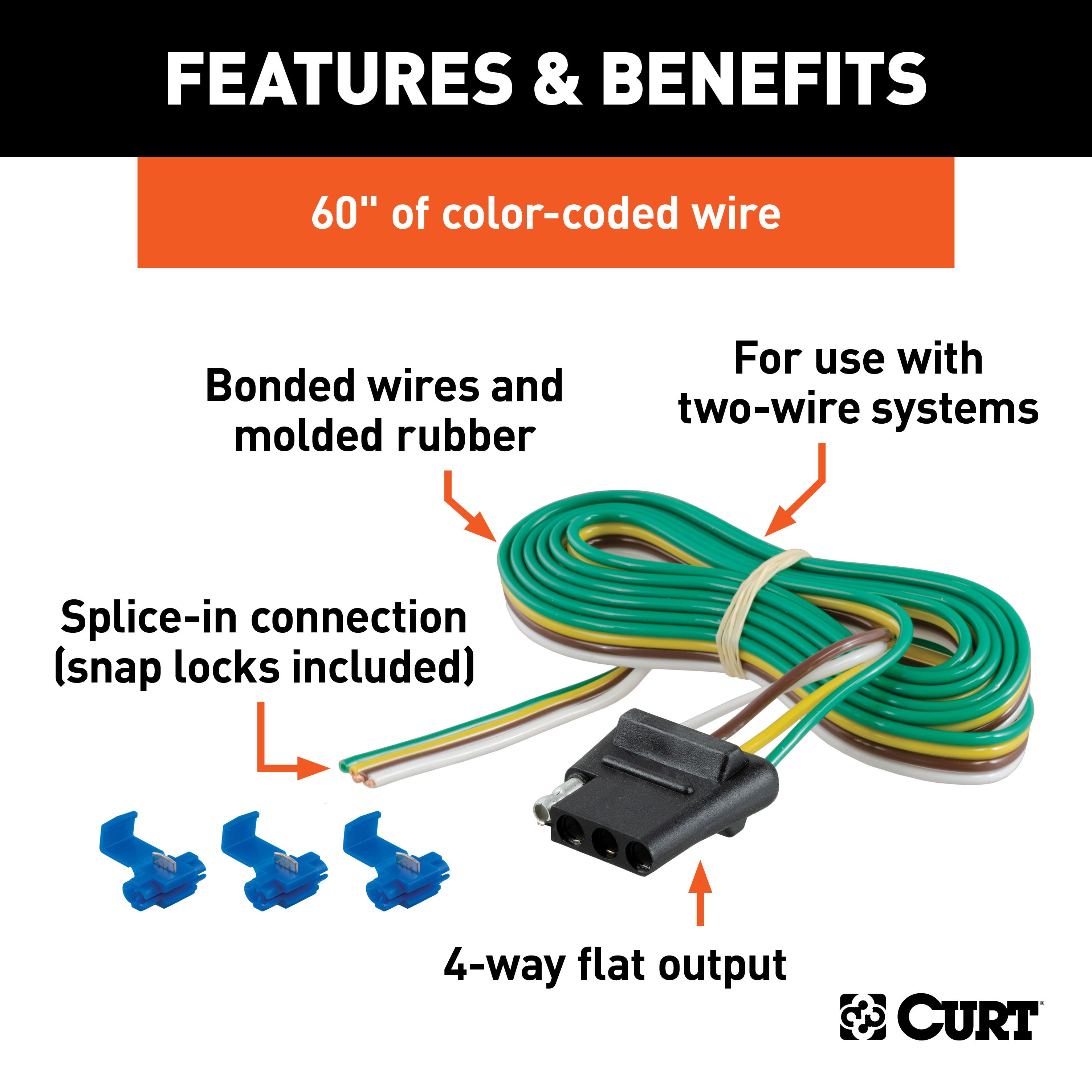
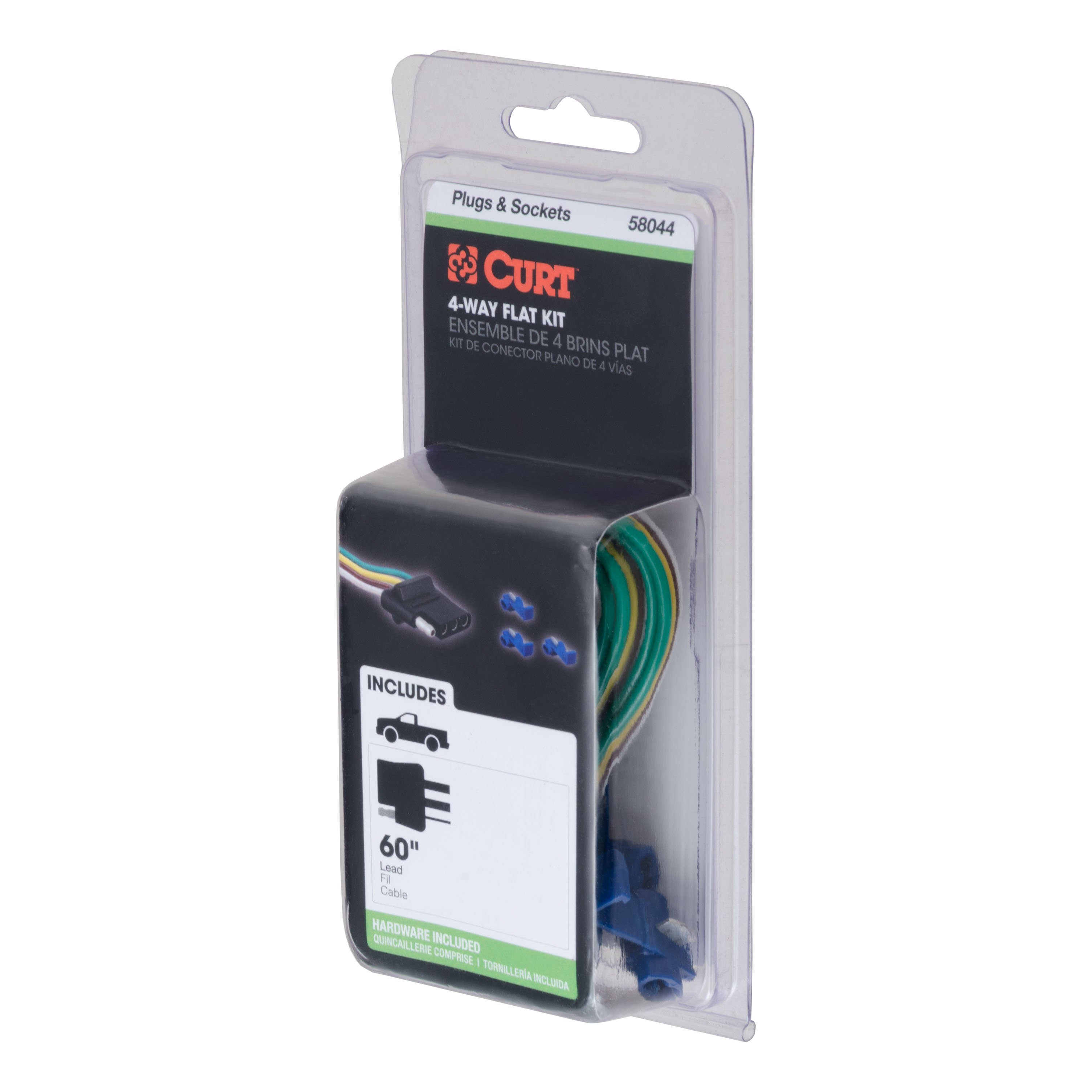
- 4-Way Flat Connector Plug w/ 60" Wires & Hardware (Requires Splicing)
- Installation instructions, schematics, diagrams, and hardware (if required).
List of Fitment Years:
2017, 2018, 2019, 2020, 2021, 2022, 2023, 2024
CURT 15445 Xtra Duty Class 5 Trailer Hitch, 2-In Receiver
Manufactured by: Curt
When we came to the limits of towing capacity, we wanted to know what else was out there What could we discover off the beaten path? So, we kept going CURT class 5 Xtra Duty hitches begin a class of their own, beyond class 4 and beyond anything the standards dictate.
They are designed for the hard road where only full-size pickup trucks, vans and SUVs dare to tread They are capable of pulling almost any heavy-duty trailer, including toy haulers, dump trailers, logging trailers, small yacht trailers and more (NOTE: Never exceed the lowest weight capacity of any towing component) This particular Xtra Duty class 5 trailer hitch offers a gross trailer weight capacity of 17,000 lbs.
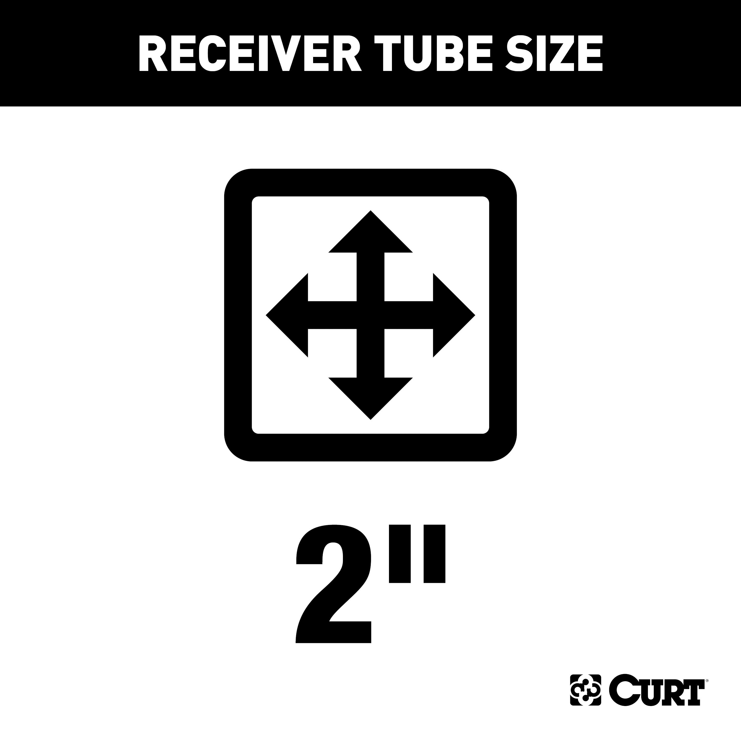
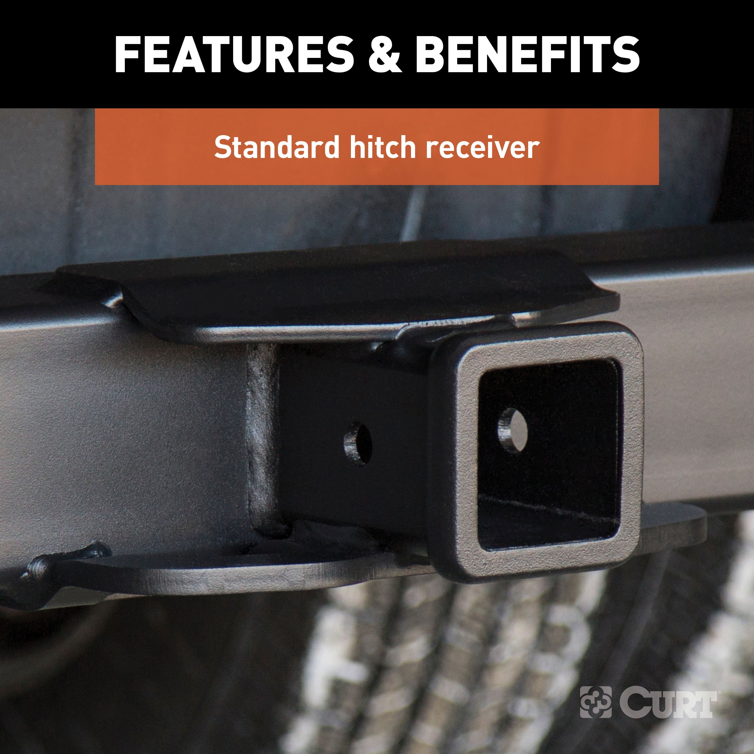
and an extra-high tongue weight capacity of 2,550 lbs It features a 2" x 2" receiver tube opening to accept a ball mount or hitch-mounted accessory, such as a cargo carrier or winch mount It is designed to be a custom-fit trailer hitch for certain years of the Ford F350 Super Duty, F450 Super Duty and F550 Super Duty (to verify compatibility with your vehicle, see application info).
For a little extra towing power and stability, this class 5 hitch can also be used in combination with a weight distributing hitch It is rated for 17,000 lbs WD and 2,550 lbs.
WDTW In our drive to create a more powerful hitch, CURT has not neglected the finer details Our class 5 trailer hitches are welded with precision and go through multiple stages of cleaning to create a smooth surface that is ready to accept our co-cured finish.
To protect them from corrosion, chipping and UV damage, these hitches are immersed in a liquid A-coat and then finished in a high-quality black carbide powder coat They come with grade-8 mounting hardware for solid installation..
Features:
- Rated to 17,000 lbs. gross trailer weight and 2,550 lbs. tongue weight
- Compatible with weight distribution hitch (17,000 lbs. WD / 2,550 lbs. WDTW)
- Engineered with a vehicle-specific design for a custom fit
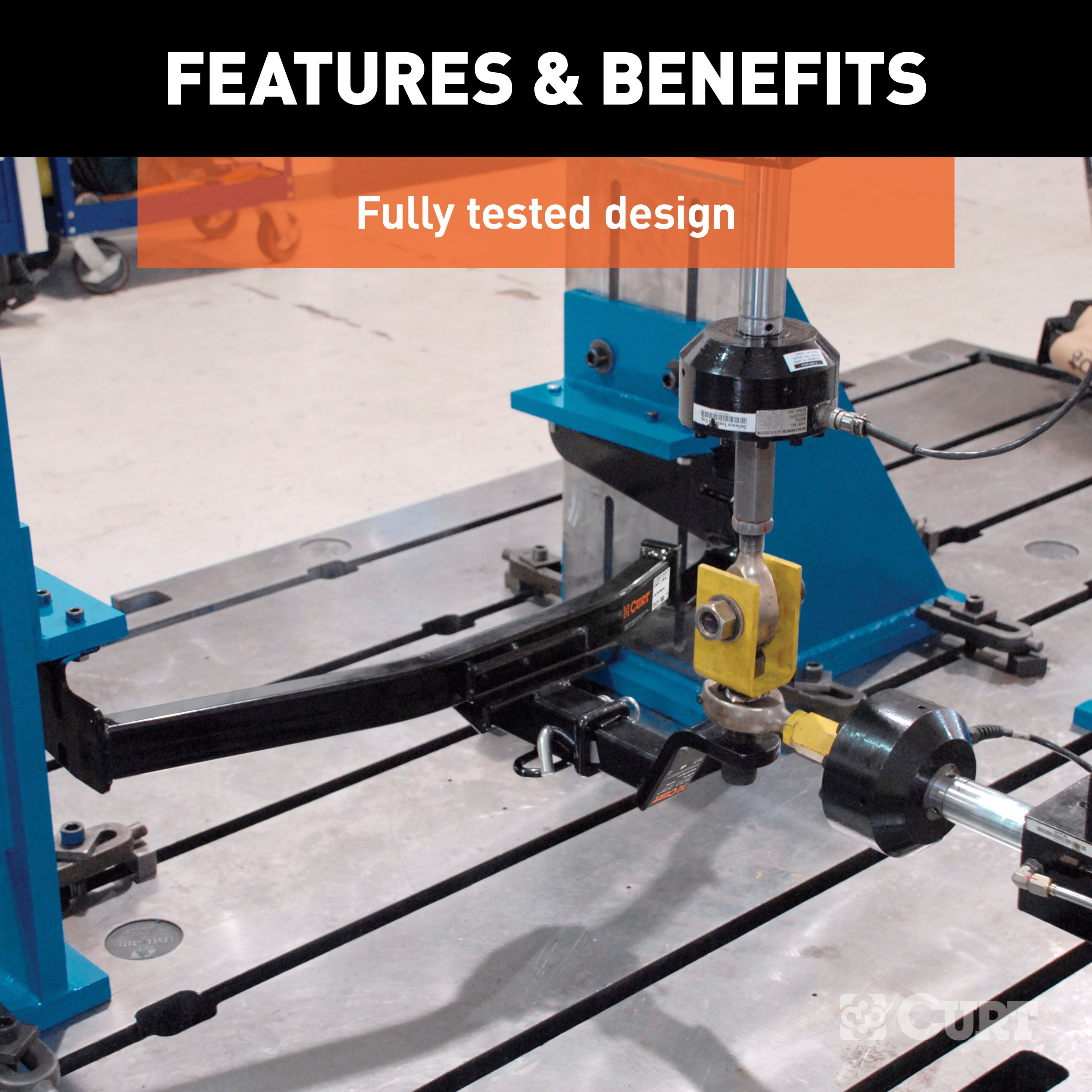
- Tested for safety in accordance with SAE J684
- Precisely welded for superior strength and fit
- Constructed with a large, powerful main body
- Protected by a highly durable carbide powder coat finish
- Co-cured in a rust-resistant liquid A-coat, inside and out
- Features wide safety chain openings for heavy-duty hooks
- Equipped with an open-back receiver for easy cleaning
- Limited lifetime warranty (one-year finish, one-year parts)
- Made in USA (may include imported hardware)
CURT 58044 Vehicle-Side 4-Pin Flat Trailer Wiring Harness with 60-Inch Wires
Manufactured by: Curt
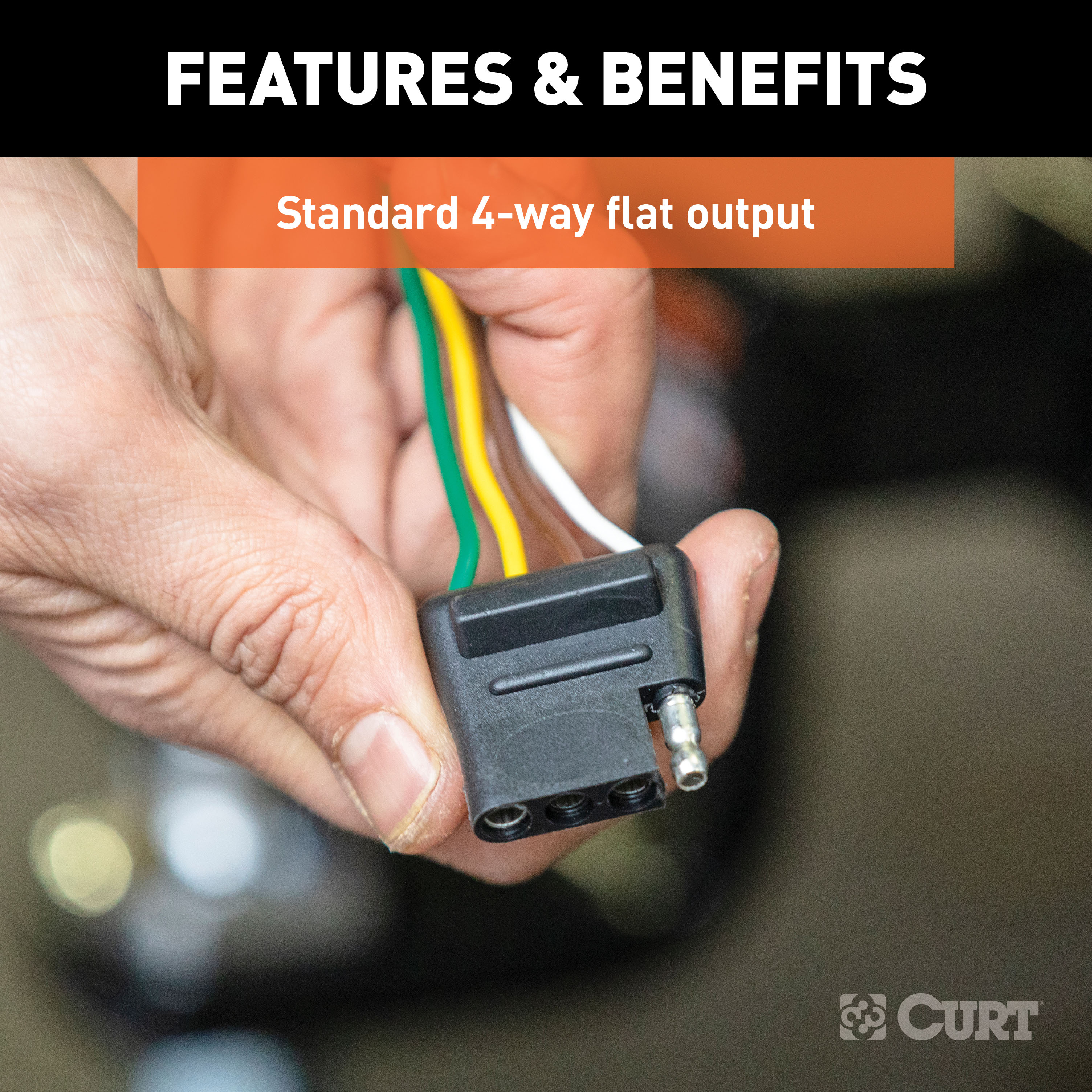
Like trailer hitches and ball mounts, electrical connectors range all over the board in shape, size and capability, but no matter what your trailer's electrical functions are, you need a solid connection to keep the power flowing and ensure safety on the road CURT electrical connectors are designed and manufactured to give you a reliable connection every time you plug in your trailer This 4-way flat connector is designed to supply power for tail lights, turn signals and brake lights, as well as a ground connection.
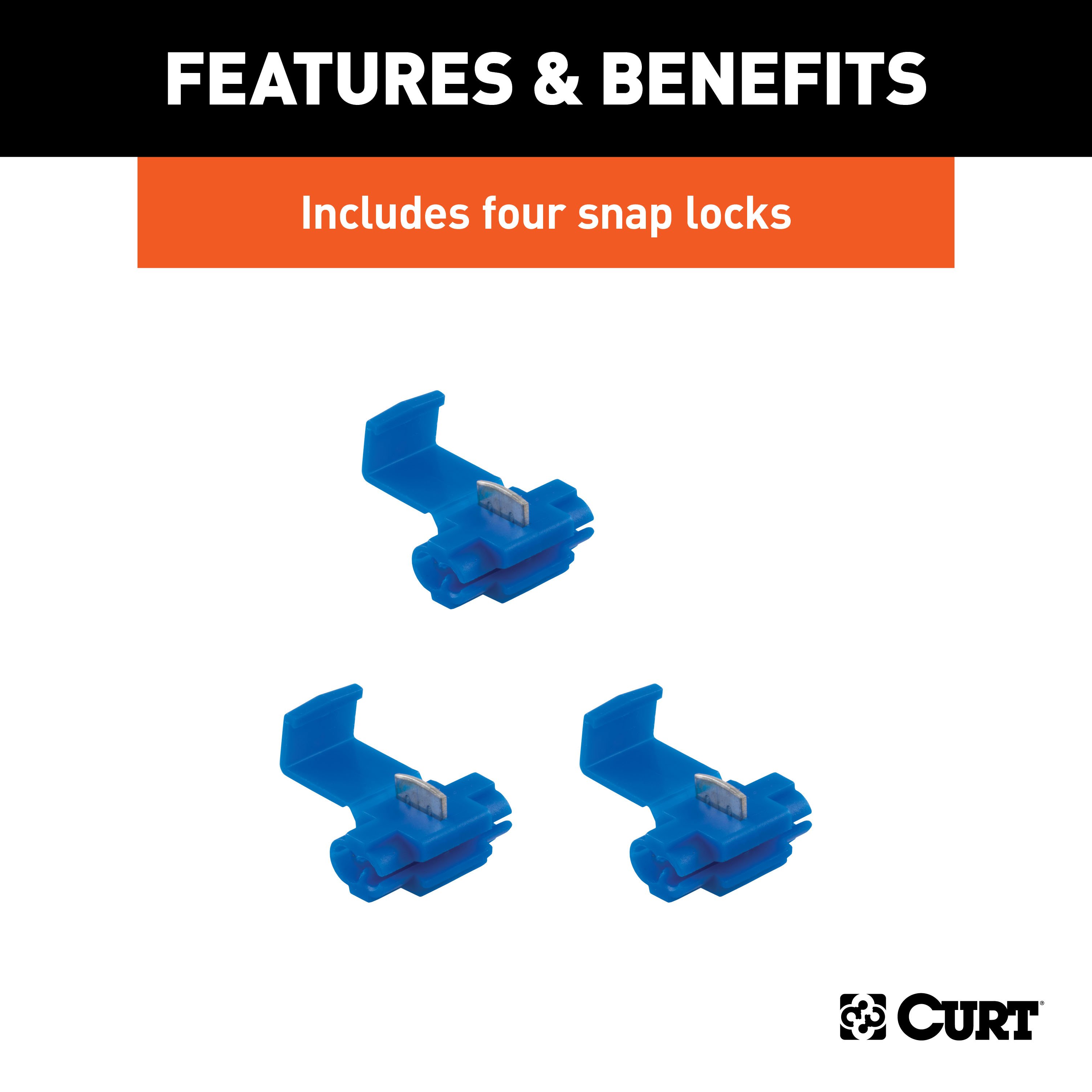
It features durable rubber-molded construction and is made with 60" of standard color-coded, bonded wire It also includes snap locks and all necessary installation hardware to easily splice into your vehicle's wiring system This 4-way flat connector is a female-end socket, specifically designed for the car side of the connection.
It is compatible with all 2-wire vehicle systems..
Features:
- Splices into vehicle wiring to provide a connection for a trailer plug
- 4-way flat output connects tail lights, brake lights and turn signals
- Constructed with bonded 16-gauge wires and durable molded rubber
- Features 60" of color-coded wire for easier installation
- Snap locks included for fast, secure splicing
- Designed for use on vehicles and trailers with two-wire systems
Hitches Near Me: We operate out of several warehouses across the country, ensuring faster delivery to your location.
$463 99 $668.90 31% OFF
- Best Price on Web Guarantee
- Fastest Shipping
- FREE Shipping
- In Stock

We match lower prices from major authorized retailers for brand-new products in original packaging, provided the item is in stock. The competing seller must be an authorized, professional retail business; offers from
individuals, auctions, peer-to-peer sites, or unauthorized sellers don’t qualify. Used, refurbished, or open-box items are excluded.
Please see our full terms for details.
Verify Fitment
View products that fit your vehicle
Fits 's with the following styles:
View products that fit your vehicle
Fits 's with the following styles:
$668.90 $463 99
 Learn more
Questions? Call our Auto Experts at (877) 869-6690
Get it now, pay later
Select installments at checkout to split your purchase into 4 interest-free payments of $ every 2 weeks.
- No fees, ever.
- No impact on your credit score.
Payment options are offered by Affirm and are subject to an eligibility check and might not be available in all states. CA Residents: Loans by Affirm Loan Services, LLC are made or arranged pursuant to a California Finance Lender license.
Installments in partnership with


Each may be shipped from a separate location, and therefore, may arrive at different times
Product Details
- Brand: Curt
- Model: 15445 58044-CH1674
- Includes: Xtra Duty Class 5 Trailer Tow Hitch, 4-Way Flat Connector Socket with 60" Wires
Compatibility Chart
| Year Range | Make | Model | Style |
|---|
This Trailer Tow Hitch + 4-Flat Fits The Following Vehicles:
2017 - 2024 Ford F-450 Super Duty Cab & Chassis w/ 34" Frame
This Trailer Tow Hitch + 4-Flat Includes the Following Parts:
- Xtra Duty Class 5 Trailer Hitch, 2" Receiver (Drilling Required)
- 4-Way Flat Connector Plug w/ 60" Wires & Hardware (Requires Splicing)
- Installation instructions, schematics, diagrams, and hardware (if required).
List of Fitment Years:
2017, 2018, 2019, 2020, 2021, 2022, 2023, 2024
CURT 15445 Xtra Duty Class 5 Trailer Hitch, 2-In Receiver
Manufactured by: Curt
When we came to the limits of towing capacity, we wanted to know what else was out there What could we discover off the beaten path? So, we kept going CURT class 5 Xtra Duty hitches begin a class of their own, beyond class 4 and beyond anything the standards dictate.
They are designed for the hard road where only full-size pickup trucks, vans and SUVs dare to tread They are capable of pulling almost any heavy-duty trailer, including toy haulers, dump trailers, logging trailers, small yacht trailers and more (NOTE: Never exceed the lowest weight capacity of any towing component) This particular Xtra Duty class 5 trailer hitch offers a gross trailer weight capacity of 17,000 lbs.
and an extra-high tongue weight capacity of 2,550 lbs It features a 2" x 2" receiver tube opening to accept a ball mount or hitch-mounted accessory, such as a cargo carrier or winch mount It is designed to be a custom-fit trailer hitch for certain years of the Ford F350 Super Duty, F450 Super Duty and F550 Super Duty (to verify compatibility with your vehicle, see application info).
For a little extra towing power and stability, this class 5 hitch can also be used in combination with a weight distributing hitch It is rated for 17,000 lbs WD and 2,550 lbs.
WDTW In our drive to create a more powerful hitch, CURT has not neglected the finer details Our class 5 trailer hitches are welded with precision and go through multiple stages of cleaning to create a smooth surface that is ready to accept our co-cured finish.
To protect them from corrosion, chipping and UV damage, these hitches are immersed in a liquid A-coat and then finished in a high-quality black carbide powder coat They come with grade-8 mounting hardware for solid installation..
Features:
- Rated to 17,000 lbs. gross trailer weight and 2,550 lbs. tongue weight
- Compatible with weight distribution hitch (17,000 lbs. WD / 2,550 lbs. WDTW)
- Engineered with a vehicle-specific design for a custom fit
- Tested for safety in accordance with SAE J684
- Precisely welded for superior strength and fit
- Constructed with a large, powerful main body
- Protected by a highly durable carbide powder coat finish
- Co-cured in a rust-resistant liquid A-coat, inside and out
- Features wide safety chain openings for heavy-duty hooks
- Equipped with an open-back receiver for easy cleaning
- Limited lifetime warranty (one-year finish, one-year parts)
- Made in USA (may include imported hardware)
CURT 58044 Vehicle-Side 4-Pin Flat Trailer Wiring Harness with 60-Inch Wires
Manufactured by: Curt
Like trailer hitches and ball mounts, electrical connectors range all over the board in shape, size and capability, but no matter what your trailer's electrical functions are, you need a solid connection to keep the power flowing and ensure safety on the road CURT electrical connectors are designed and manufactured to give you a reliable connection every time you plug in your trailer This 4-way flat connector is designed to supply power for tail lights, turn signals and brake lights, as well as a ground connection.
It features durable rubber-molded construction and is made with 60" of standard color-coded, bonded wire It also includes snap locks and all necessary installation hardware to easily splice into your vehicle's wiring system This 4-way flat connector is a female-end socket, specifically designed for the car side of the connection.
It is compatible with all 2-wire vehicle systems..
Features:
- Splices into vehicle wiring to provide a connection for a trailer plug
- 4-way flat output connects tail lights, brake lights and turn signals
- Constructed with bonded 16-gauge wires and durable molded rubber
- Features 60" of color-coded wire for easier installation
- Snap locks included for fast, secure splicing
- Designed for use on vehicles and trailers with two-wire systems
Hitches Near Me: We operate out of several warehouses across the country, ensuring faster delivery to your location.
| Default | |
| Brand | Curt |
| Gross Towing Weight | 17,000 LB |
| Trailer Hitch Receiver Size | 2 Inch |
| Trailer Wiring Output Type | 4-Flat |
| Hitch Class | 5 |
| Trailer Wiring Install Style | Hardwire |
| Drilling Required | Yes |
| Tongue Weight Capacity | 2,550 LB |
| Gross Towing Weight w/ Weight Distribution Kit | 17,000 LB |
| Maximum Tongue Weight w/ Weight Distribution Kit | 2,550 LB |
| Hitch Visibility | Exposed |
| Cross-Tube Type | Square Tube |
Ask a Question about For 2017-2024 Ford F450 Super Duty Trailer Hitch + Wiring 4 Pin Fits Cab & Chassis w/ 34" Frame Curt 15445 58044 2 inch Tow Receiver
Be the first to ask a question.


