





For 2021-2023 Hyundai Elantra Trailer Hitch + Wiring 4 Pin Except N N Line or Hybrid Curt 11630 56470 1-1/4 Tow Receiver
Model: 11630 56470-CH2335This Trailer Tow Hitch + 4-Flat Fits The Following Vehicles:
2021 - 2023 Hyundai Elantra Except N N Line or Hybrid
This Trailer Tow Hitch + 4-Flat Includes the Following Parts:
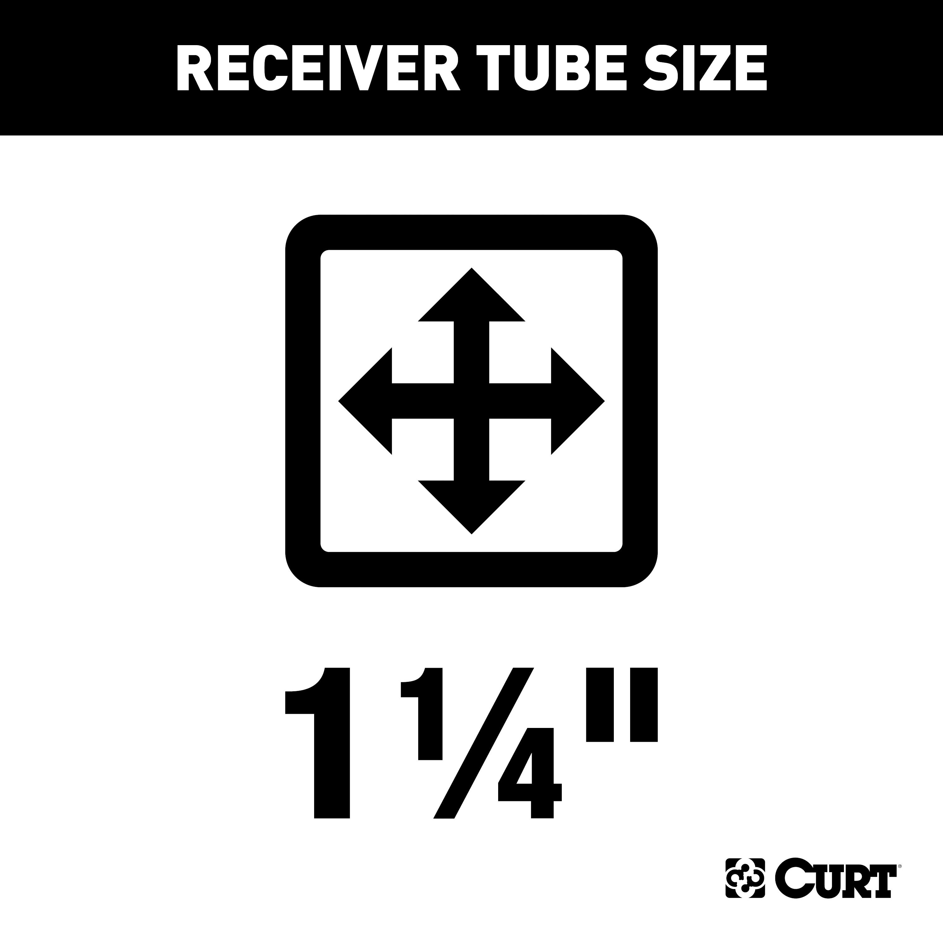
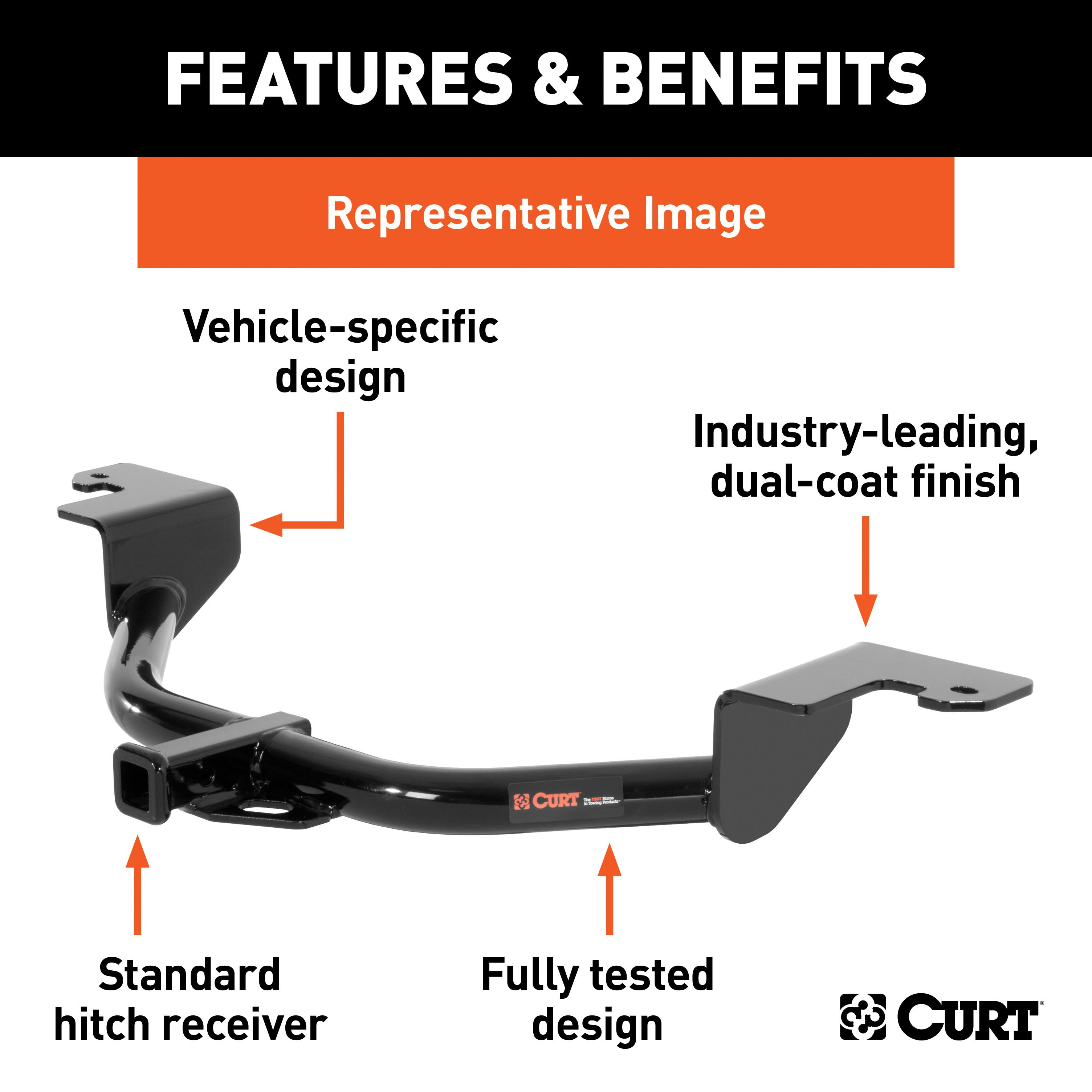
- Class 1 Hitch, 1-1/4" Receiver (Drilling Required)
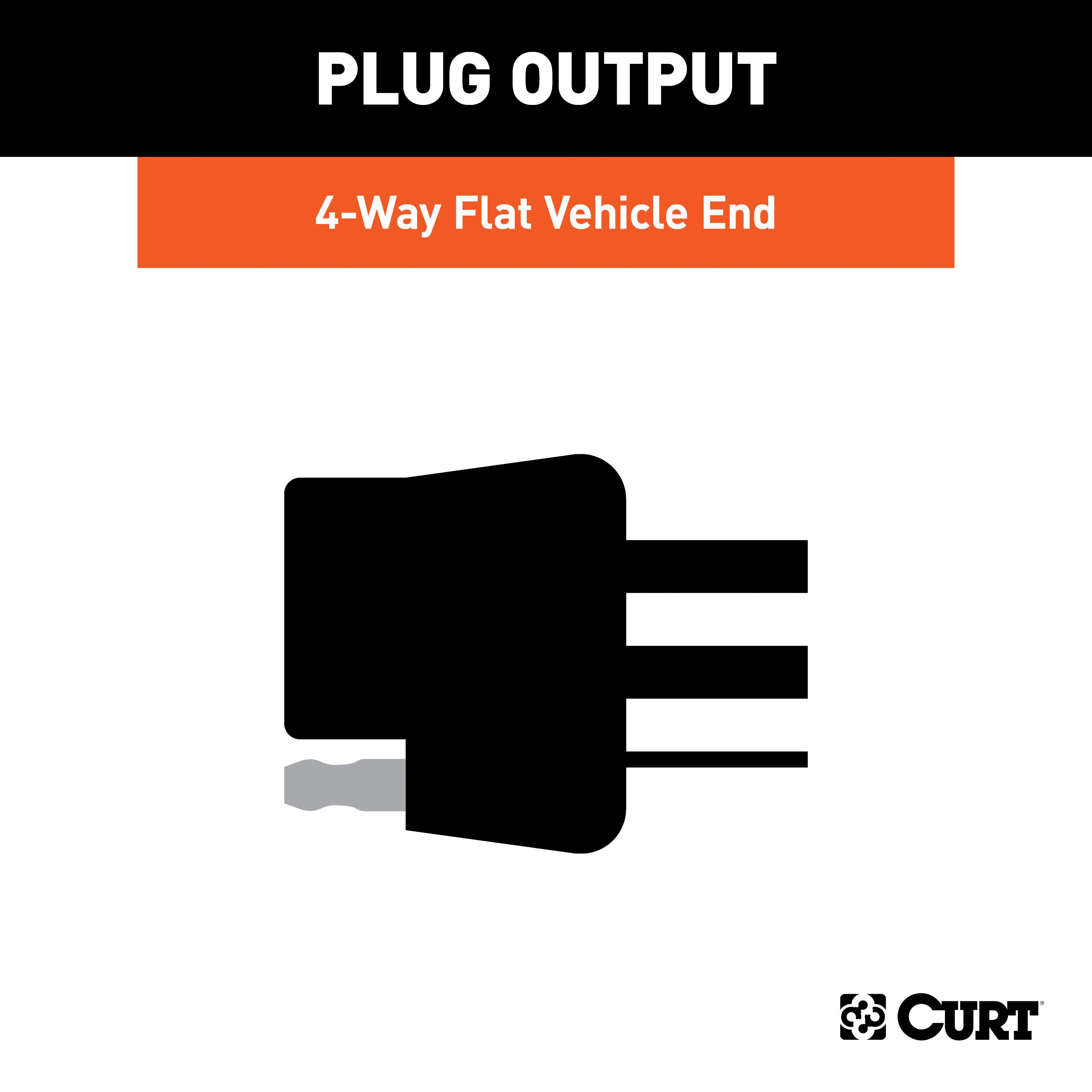
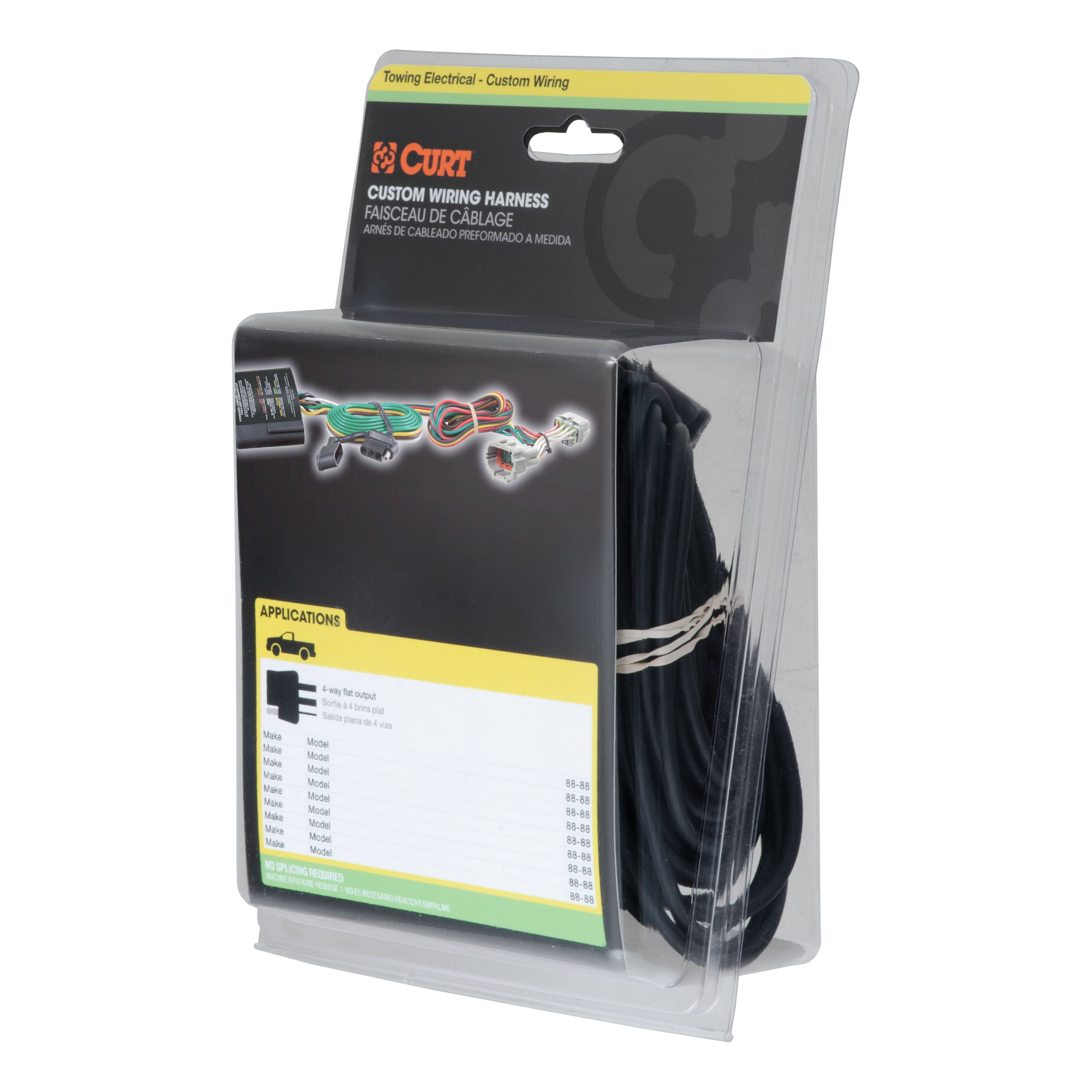
- Custom Wiring Harness, 4-Way Flat Output (Plug & Play)
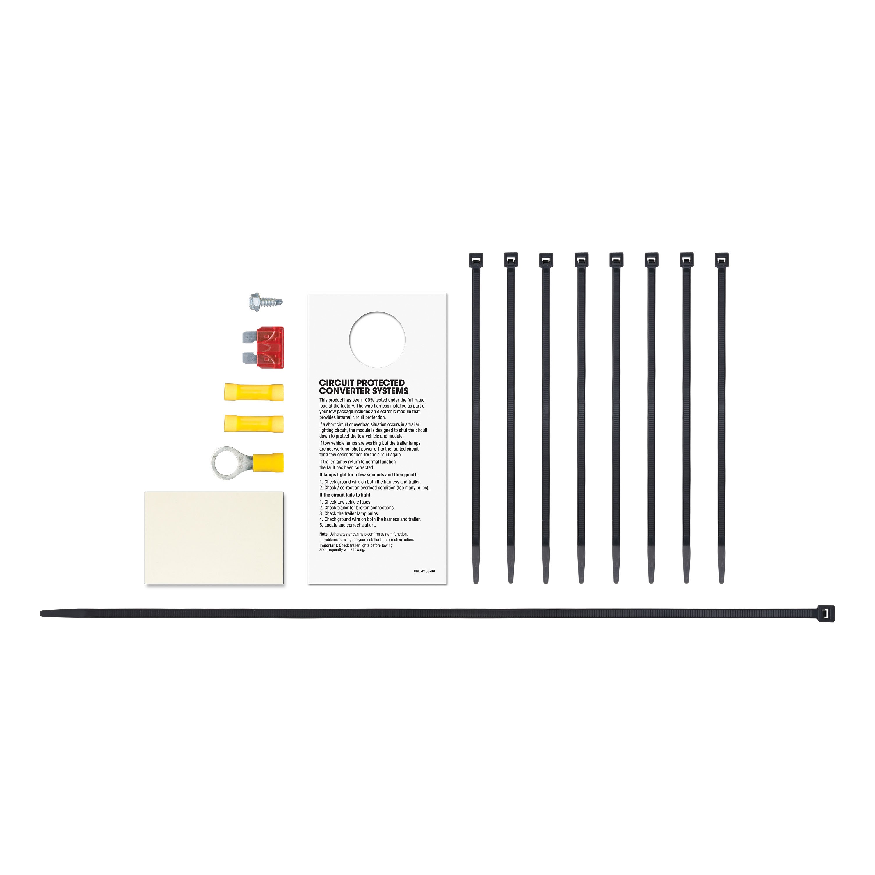
- Installation instructions, schematics, diagrams, and hardware (if required).
List of Fitment Years:
2021, 2022, 2023
CURT 11630 Class 1 Trailer Hitch, 1-1/4-Inch Receiver
Manufactured by: Curt
However you define adventure -- whether it's climbing onto the back of a mountain bike, hunting from the top of a tree stand or camping with the family a long way from nowhere -- CURT class 1 hitches provide a light-duty towing receiver to help you Bring It Each is made to fit a specific vehicle, providing easier installation, a better fit and optimal towing capacity Custom class 1 trailer hitches are available for a variety of smaller vehicle types, including the compact car, crossover, minivan and small SUV.
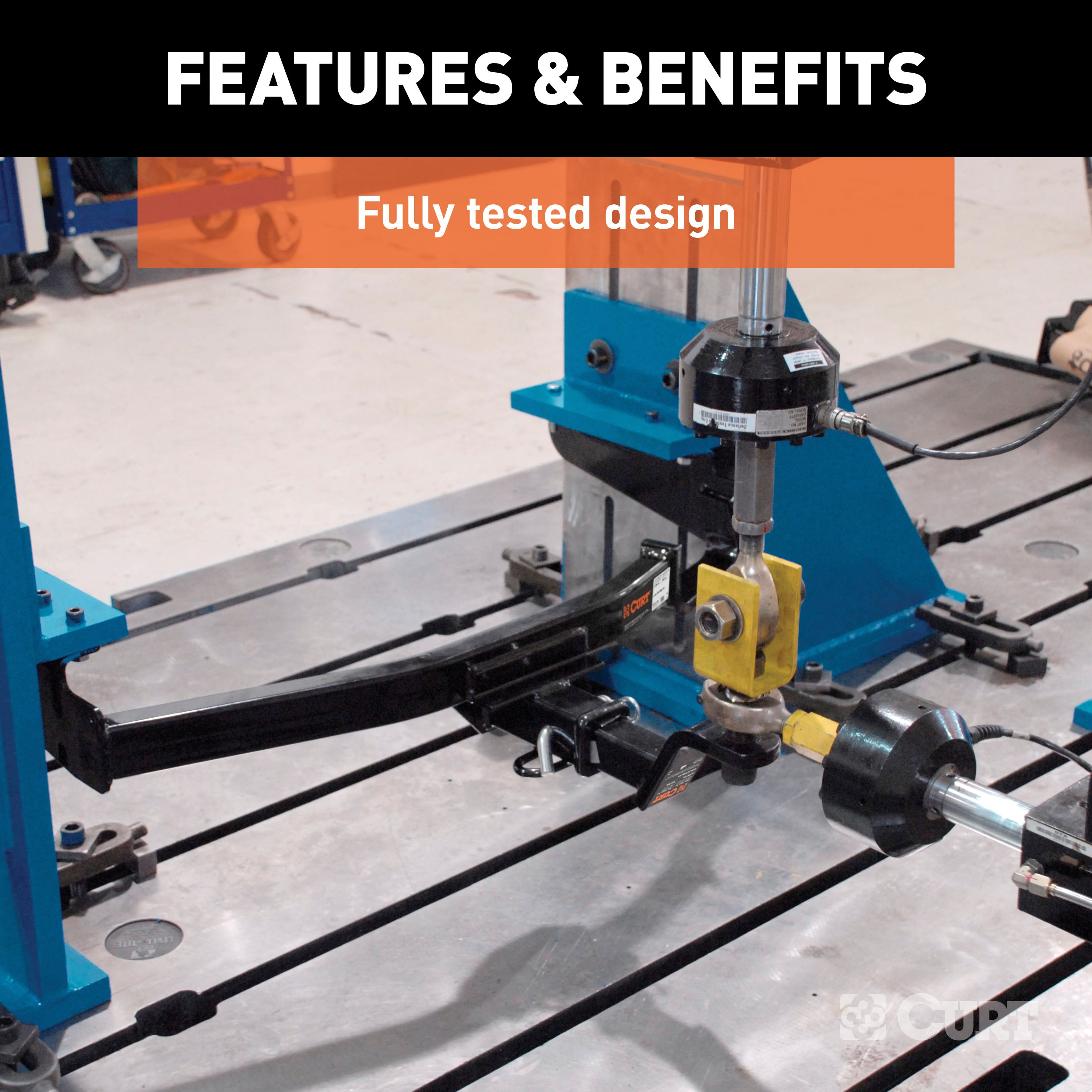
This particular class 1 hitch is designed to be a custom hitch for certain years of the Hyundai Elantra (excluding N and N Line; to verify vehicle compatibility, see the CURT fitment guide at trailerjacks.com) Tested in accordance with SAE J684, it offers a weight carrying capacity of 2,000 lbs GTW and 200 lbs.
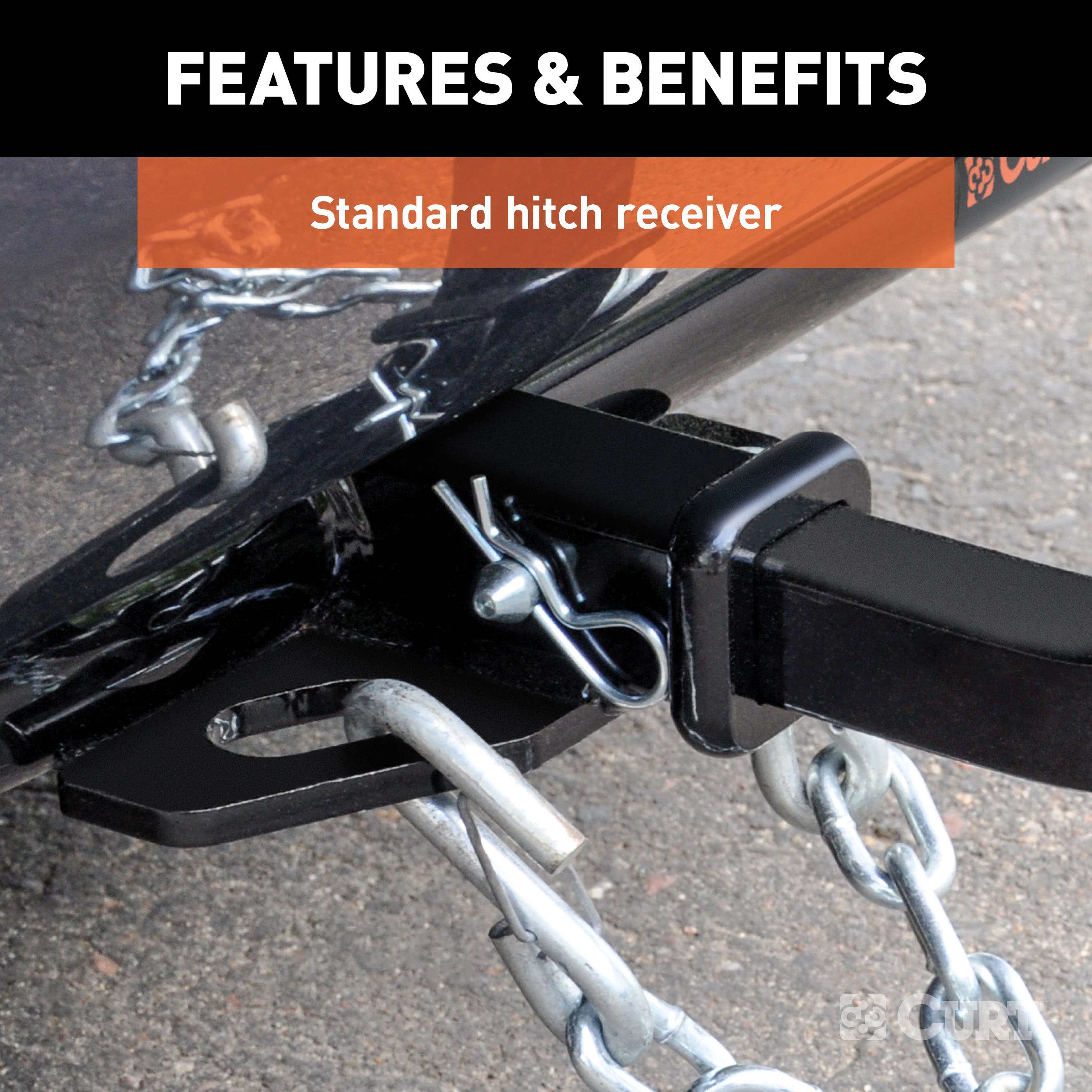
TW It is equipped with 1-1/4" receiver tube opening to accept a ball mount shank or other hitch mount This class 1 hitch also comes with all necessary mounting hardware.
With its lightweight design and smaller receiver tube size, a class 1 hitch is especially useful for adding cargo space with a hitch-mounted bike rack or cargo carrier They can also typically be used to tow small trailers such as a utility trailer, kayak trailer or teardrop camper (never exceed the lowest weight capacity of any towing component; i.e the vehicle, hitch, trailer, etc).
Though CURT class 1 trailer hitches are only intended for light-duty towing, we apply the same principles of quality as we do to the rest of our rear mount hitches Each class 1 hitch is made with hands-on engineering, high-strength steel and precise welding We use a co-cured finish of liquid A-coat, inside and out, and durable black powder coat to provide a lasting defense against rust, chips and UV rays..
Features:
- Rated to 2,000 lbs. gross trailer weight and 200 lbs. tongue weight
- Engineered with a vehicle-specific design for a custom fit
- Tested for safety in accordance with SAE J684
- Precisely welded for superior strength and fit
- Protected by a durable high-gloss black powder coat finish
- Co-cured in a rust-resistant liquid A-coat, inside and out
- Equipped with an open-back receiver for easy cleaning
- Limited lifetime warranty (one-year finish, one-year parts)
- Made in USA (may include imported hardware)
CURT 56470 Vehicle-Side Custom 4-Pin Trailer Wiring Harness
Manufactured by: Curt
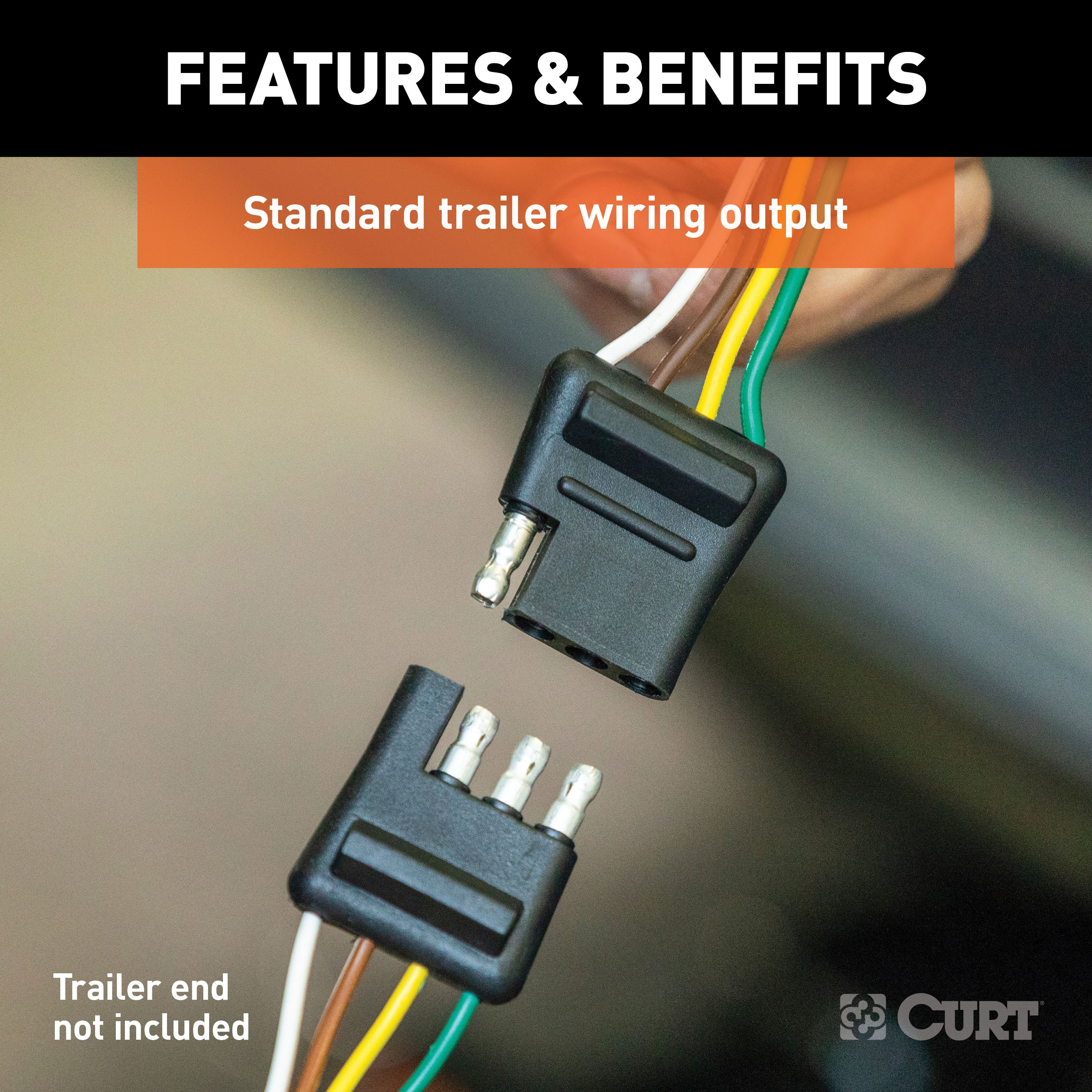
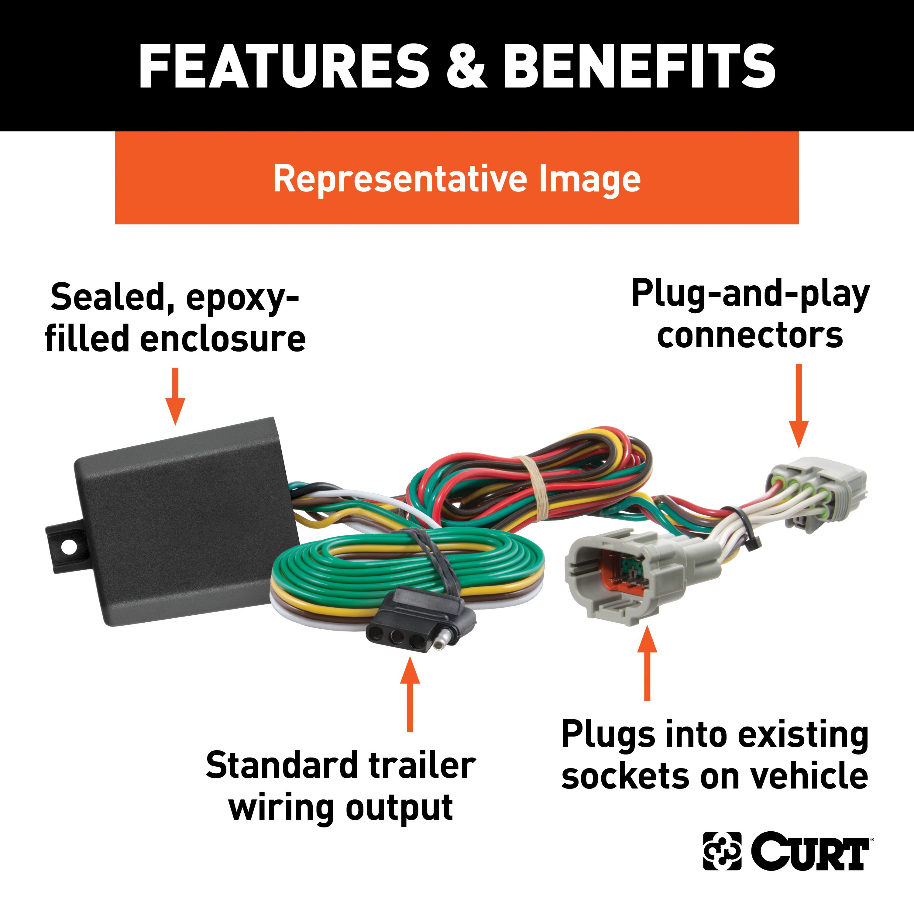
If your vehicle is not equipped with wiring for towing a trailer, CURT custom wiring is the ideal solution A custom wiring harness -- also called a T-connector -- is a simple, plug-and-play electrical device that plugs into your automotive electric system and provides a standard, universal trailer wiring connection This is done using two or more vehicle-specific, OEM-compatible connectors to plug into the taillight assembly, eliminating the need for cutting, splicing and soldering during installation.
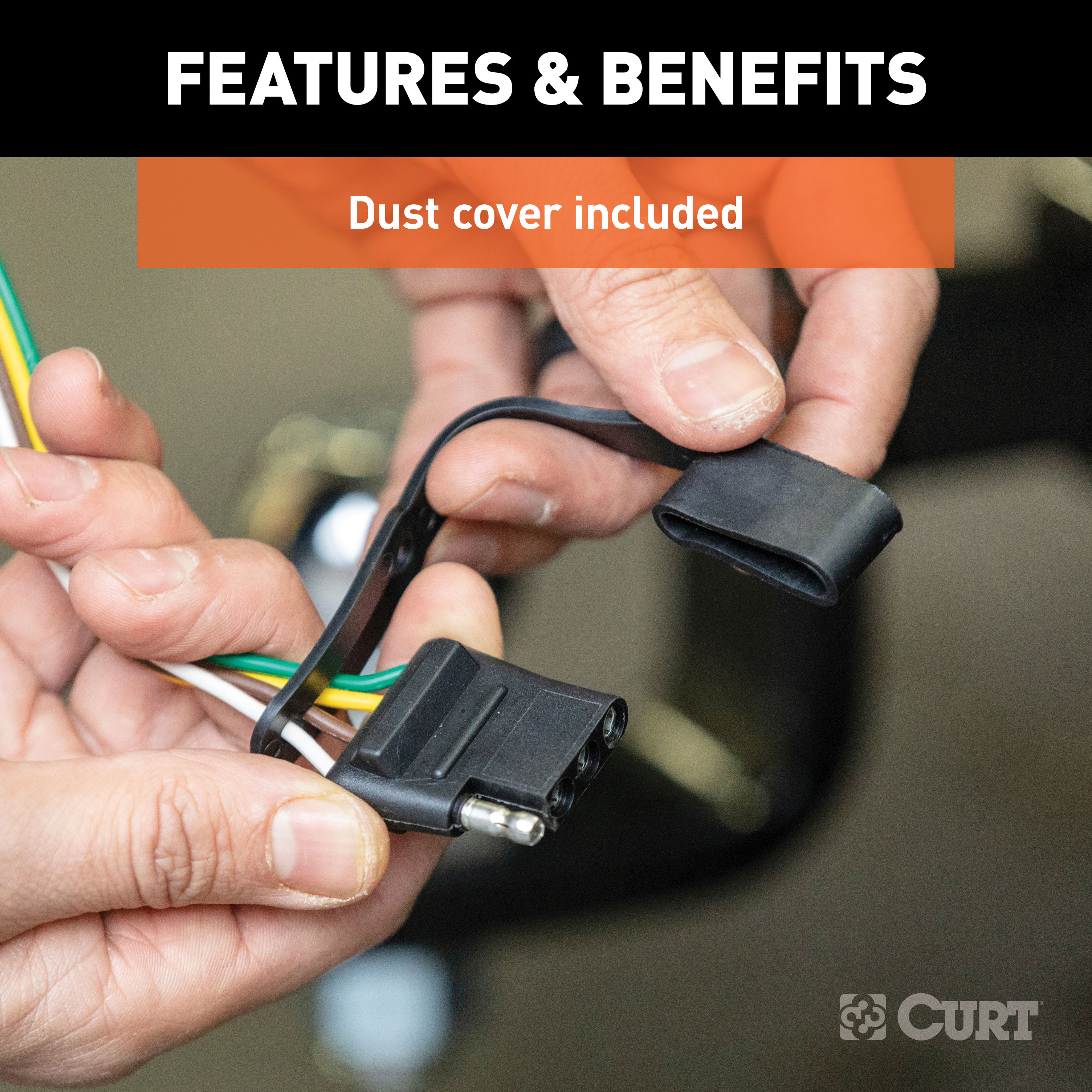
Custom wiring harnesses are made vehicle-specific, and while they are not available for all vehicles, they do offer one of the fastest, easiest and most secure ways to wire a vehicle for towing This particular plug-in harness provides a 4-way flat connector socket and is designed to be a custom wiring harness to fit certain years of the Hyundai Elantra (to verify your vehicle compatibility, see application info) It comes with all necessary wiring components to establish a reliable trailer wiring connection, as well as a dust cover to keep the connector clean when not in use.
You have a picture in mind of your next destination -- maybe it's the boat landing at your favorite fishing spot, maybe it's a campsite that overlooks one of nature's masterpieces, or maybe it's the next big jobsite However, turning that picture into a reality takes more than just daydreaming It takes a solid connection and the right amount of power.
CURT custom wiring is made with some of the most sophisticated technology in the industry and is designed to install with ease, giving you a long-lasting electrical connection for your towing hitch setup..
Features:
- Plugs into vehicle tail light assembly to provide a 4-way flat socket
- Simple plug-and-play design eliminates the need for cutting or splicing
- 4-way flat output connects tail lights, brake lights and turn signals
- Equipped with tail light converter for vehicle-trailer compatibility
- Constructed with SMT circuitry for better performance and durability
- Dust cover included to keep connector clean when not in use
- Backed by a limited one-year warranty
Hitches Near Me: We operate out of several warehouses across the country, ensuring faster delivery to your location.
$259 99 $391.90 34% OFF
- Best Price on Web Guarantee
- Fastest Shipping
- FREE Shipping
- In Stock

We match lower prices from major authorized retailers for brand-new products in original packaging, provided the item is in stock. The competing seller must be an authorized, professional retail business; offers from
individuals, auctions, peer-to-peer sites, or unauthorized sellers don’t qualify. Used, refurbished, or open-box items are excluded.
Please see our full terms for details.
Verify Fitment
View products that fit your vehicle
Fits 's with the following styles:
View products that fit your vehicle
Fits 's with the following styles:
$391.90 $259 99
 Learn more
Questions? Call our Auto Experts at (877) 869-6690
Get it now, pay later
Select installments at checkout to split your purchase into 4 interest-free payments of $ every 2 weeks.
- No fees, ever.
- No impact on your credit score.
Payment options are offered by Affirm and are subject to an eligibility check and might not be available in all states. CA Residents: Loans by Affirm Loan Services, LLC are made or arranged pursuant to a California Finance Lender license.
Installments in partnership with

Product Details
- Brand: Curt
- Model: 11630 56470-CH2335
- Includes: Class 1 Trailer Tow Hitch, Custom Wiring Harness
Compatibility Chart
| Year Range | Make | Model | Style |
|---|
This Trailer Tow Hitch + 4-Flat Fits The Following Vehicles:
2021 - 2023 Hyundai Elantra Except N N Line or Hybrid
This Trailer Tow Hitch + 4-Flat Includes the Following Parts:
- Class 1 Hitch, 1-1/4" Receiver (Drilling Required)
- Custom Wiring Harness, 4-Way Flat Output (Plug & Play)
- Installation instructions, schematics, diagrams, and hardware (if required).
List of Fitment Years:
2021, 2022, 2023
CURT 11630 Class 1 Trailer Hitch, 1-1/4-Inch Receiver
Manufactured by: Curt
However you define adventure -- whether it's climbing onto the back of a mountain bike, hunting from the top of a tree stand or camping with the family a long way from nowhere -- CURT class 1 hitches provide a light-duty towing receiver to help you Bring It Each is made to fit a specific vehicle, providing easier installation, a better fit and optimal towing capacity Custom class 1 trailer hitches are available for a variety of smaller vehicle types, including the compact car, crossover, minivan and small SUV.
This particular class 1 hitch is designed to be a custom hitch for certain years of the Hyundai Elantra (excluding N and N Line; to verify vehicle compatibility, see the CURT fitment guide at trailerjacks.com) Tested in accordance with SAE J684, it offers a weight carrying capacity of 2,000 lbs GTW and 200 lbs.
TW It is equipped with 1-1/4" receiver tube opening to accept a ball mount shank or other hitch mount This class 1 hitch also comes with all necessary mounting hardware.
With its lightweight design and smaller receiver tube size, a class 1 hitch is especially useful for adding cargo space with a hitch-mounted bike rack or cargo carrier They can also typically be used to tow small trailers such as a utility trailer, kayak trailer or teardrop camper (never exceed the lowest weight capacity of any towing component; i.e the vehicle, hitch, trailer, etc).
Though CURT class 1 trailer hitches are only intended for light-duty towing, we apply the same principles of quality as we do to the rest of our rear mount hitches Each class 1 hitch is made with hands-on engineering, high-strength steel and precise welding We use a co-cured finish of liquid A-coat, inside and out, and durable black powder coat to provide a lasting defense against rust, chips and UV rays..
Features:
- Rated to 2,000 lbs. gross trailer weight and 200 lbs. tongue weight
- Engineered with a vehicle-specific design for a custom fit
- Tested for safety in accordance with SAE J684
- Precisely welded for superior strength and fit
- Protected by a durable high-gloss black powder coat finish
- Co-cured in a rust-resistant liquid A-coat, inside and out
- Equipped with an open-back receiver for easy cleaning
- Limited lifetime warranty (one-year finish, one-year parts)
- Made in USA (may include imported hardware)
CURT 56470 Vehicle-Side Custom 4-Pin Trailer Wiring Harness
Manufactured by: Curt
If your vehicle is not equipped with wiring for towing a trailer, CURT custom wiring is the ideal solution A custom wiring harness -- also called a T-connector -- is a simple, plug-and-play electrical device that plugs into your automotive electric system and provides a standard, universal trailer wiring connection This is done using two or more vehicle-specific, OEM-compatible connectors to plug into the taillight assembly, eliminating the need for cutting, splicing and soldering during installation.
Custom wiring harnesses are made vehicle-specific, and while they are not available for all vehicles, they do offer one of the fastest, easiest and most secure ways to wire a vehicle for towing This particular plug-in harness provides a 4-way flat connector socket and is designed to be a custom wiring harness to fit certain years of the Hyundai Elantra (to verify your vehicle compatibility, see application info) It comes with all necessary wiring components to establish a reliable trailer wiring connection, as well as a dust cover to keep the connector clean when not in use.
You have a picture in mind of your next destination -- maybe it's the boat landing at your favorite fishing spot, maybe it's a campsite that overlooks one of nature's masterpieces, or maybe it's the next big jobsite However, turning that picture into a reality takes more than just daydreaming It takes a solid connection and the right amount of power.
CURT custom wiring is made with some of the most sophisticated technology in the industry and is designed to install with ease, giving you a long-lasting electrical connection for your towing hitch setup..
Features:
- Plugs into vehicle tail light assembly to provide a 4-way flat socket
- Simple plug-and-play design eliminates the need for cutting or splicing
- 4-way flat output connects tail lights, brake lights and turn signals
- Equipped with tail light converter for vehicle-trailer compatibility
- Constructed with SMT circuitry for better performance and durability
- Dust cover included to keep connector clean when not in use
- Backed by a limited one-year warranty
Hitches Near Me: We operate out of several warehouses across the country, ensuring faster delivery to your location.
| Default | |
| UPC | 612314116300, 612314564705 |
| Item Weight | 25.000, 1.670 |
| Country of Manufacture | US |
| Main Body Shape | Round |
| Receiver Tube Size | 1-1/4 IN |
| Finish | GLOSS BLACK POWDER COAT, Blank |
| WC / TW (Pounds) | 200 LBS / 2,000 LBS |
| Weight Carrying Capacity (Pounds) | 2,000 LBS |
| WC Tongue Weight (Pounds) | 200 LBS |
| Installation Difficulty | Advanced, Professional |
| Installation Time Exact (Minutes) | 90, 45 |
| Note 1 | Trailer hitch weight ratings are limited to vehicle manufacturer's stated capacities, Vehicle battery connection required |
| Note 2 | Includes installation hardware |
| Warranty | Limited Lifetime Warranty (One-Year Finish, One-Year Parts), One-Year Limited Warranty |
Ask a Question about For 2021-2023 Hyundai Elantra Trailer Hitch + Wiring 4 Pin Except N N Line or Hybrid Curt 11630 56470 1-1/4 Tow Receiver
Be the first to ask a question.


