Product Details
- Brand: Curt
- Model: 11307 56043-CH219
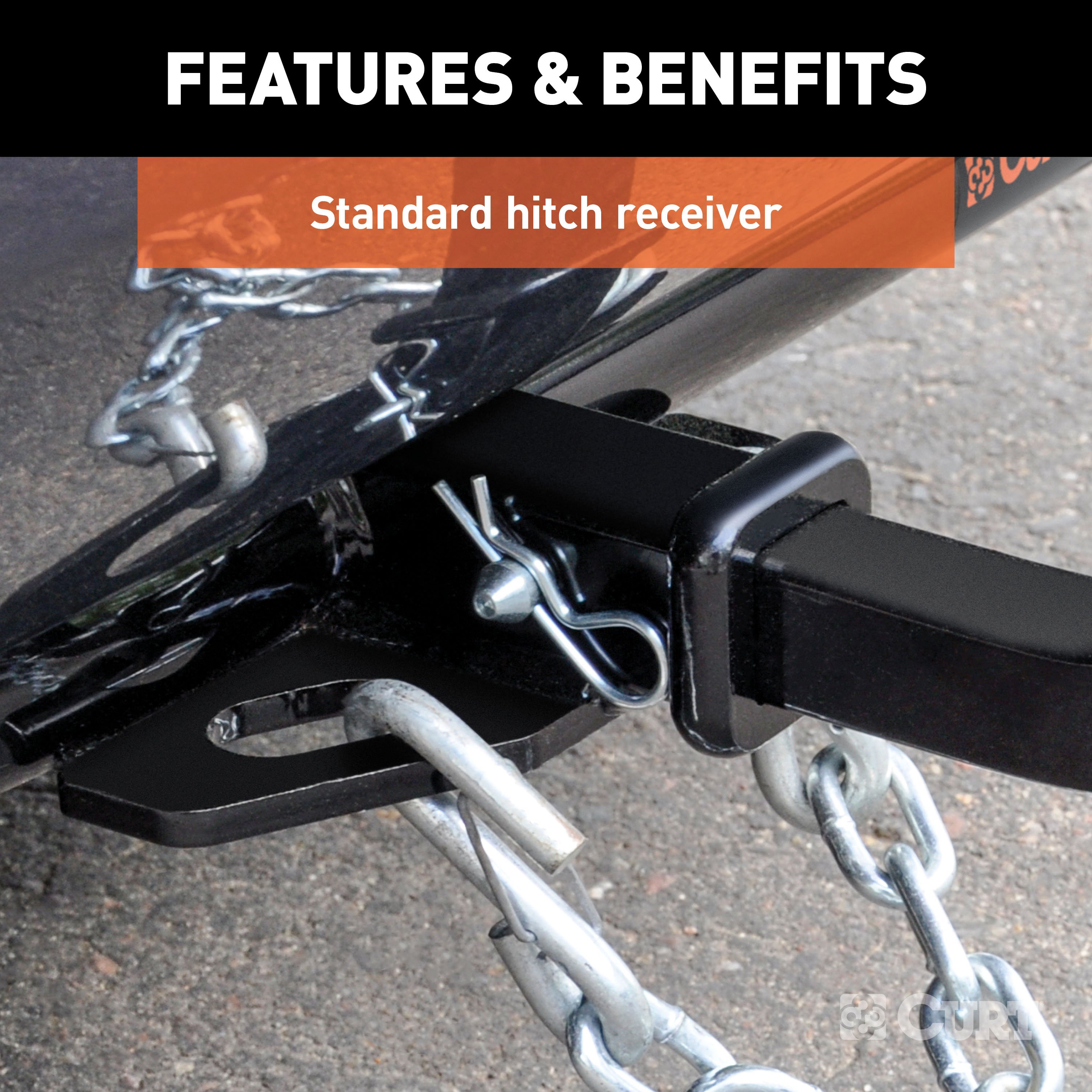
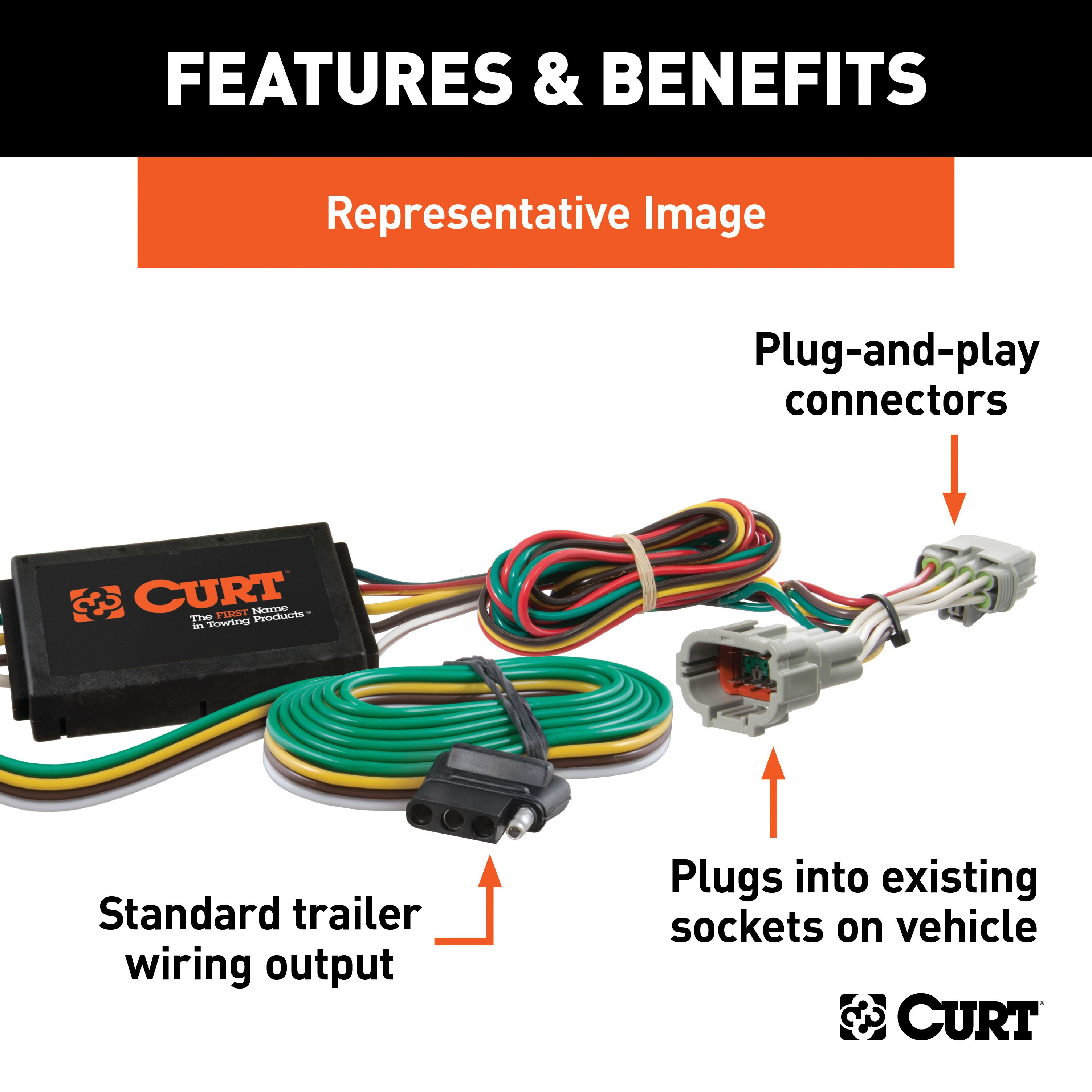
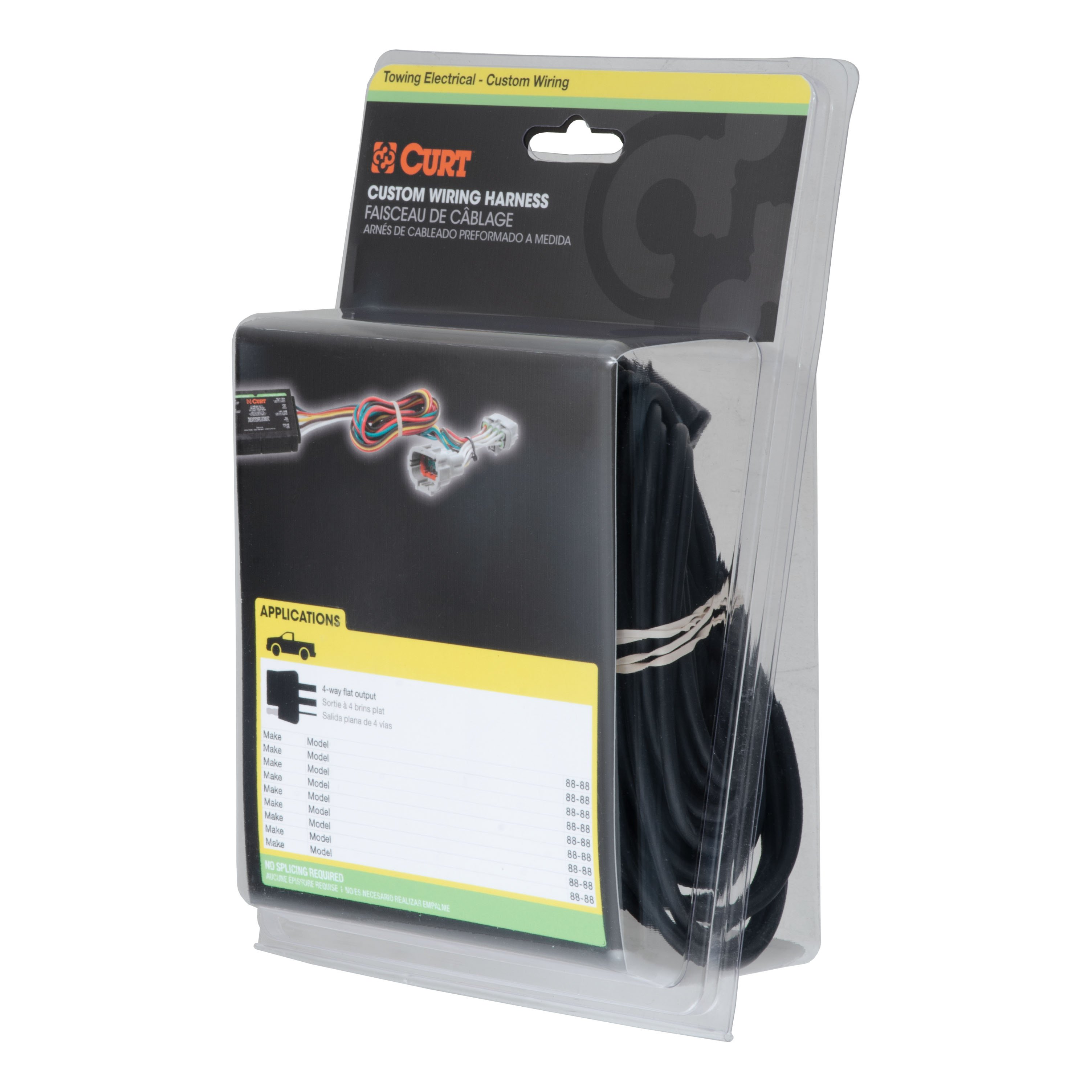
- Includes: Class 1 Trailer Tow Hitch, Custom Wiring Harness
Compatibility Chart
Get Expert Help
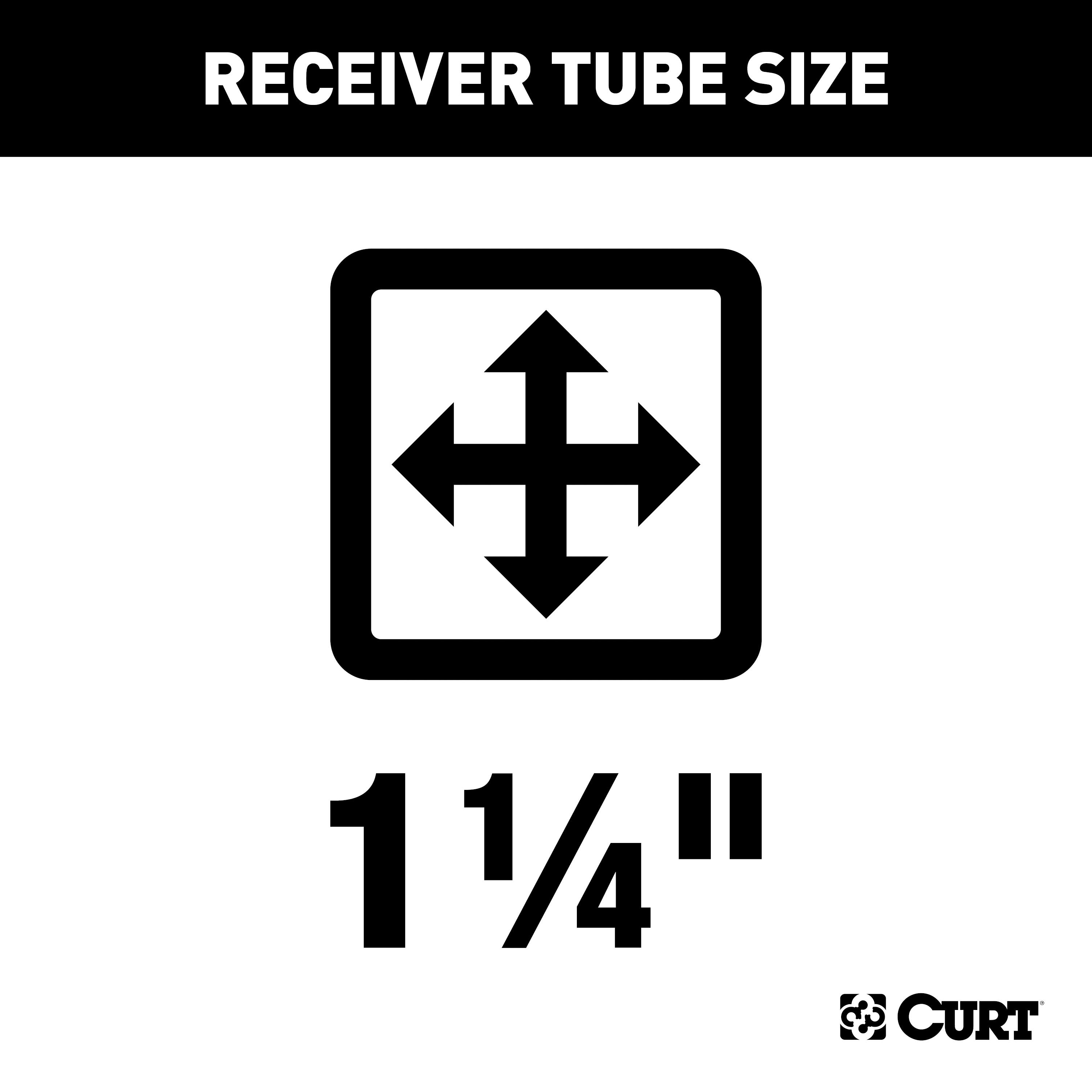
For 2003-2007 Cadillac CTS Trailer Hitch + Wiring 4 Pin Fits Sedan Curt 11307 56043 1-1/4 Tow Receiver Install Notes
Installation Instructions for 2003-2007 Cadillac CTS & STS 4-Door Sedan
Part Numbers:
- 11307
Tools Required:
- Torque wrench
- Ratchet
- 3/4" socket
- Power drill
- 1/2" drill bit
Step-by-Step Instructions:
-
Lower the Muffler:
- Remove the two rear exhaust hangers and one forward exhaust hanger to lower the muffler(s).
-
Access Trunk Pan:
- Open the trunk and remove the spare tire cover.
- Roll back the carpet and padding to expose the bare metal floor of the trunk pan.
-
Position the Hitch:
- Raise the hitch into position.
- Align the rear edge of the hitch side plates flush with the frame end plates and center it side to side.
-
Mark and Drill Holes:
- Use the hitch as a template to mark and center punch three mounting holes on both sides of the trunk pan.
- Lower the hitch and drill 1/8" pilot holes through the center-punched locations.
- Enlarge the holes to 1/2".
-
Install Spacer Plates and Carriage Bolts:
- Place the spacer plates over the drilled holes inside the trunk.
- Insert the 7/16" carriage bolts through the plates and trunk pan.
- Note: Seal all holes drilled in the vehicle to prevent exhaust fumes from entering the trunk.
-
Secure the Hitch:
- Raise the hitch into position and install the 7/16" flange nuts onto the carriage bolts.
-
Torque Fasteners:
- Torque all 7/16" fasteners to 70 lb-ft.
-
Reassemble the Vehicle:
- Roll the carpet and padding back into place.
- Reinstall the spare tire cover.
- Reattach the three exhaust hangers removed in Step 1.
Hardware List:
- Carriage Bolt, 7/16-14 x 1-3/4, Grade 8: Qty 6
- Spacer Plate, .250" thick: Qty 2
- Hex Flange Nut, 7/16-14, Grade 8: Qty 6
Safety Notes:
- Gross Load Capacity (Weight Carrying Hitch): 2,000 lbs (trailer weight), 200 lbs (tongue weight).
- Warning: Non-trailer loads must be supported with auxiliary stabilizing straps to prevent damage.
- Failure to support non-trailer loads properly will void the product warranty.
- Do not exceed the vehicle manufacturer's recommended towing capacity.
Specifications:
- Hitch Weight: Not specified
- Installation Time:
- Professional: 34 minutes
- Novice (DIY): 60 minutes
- Drilling Required: Yes
- Lowering Exhaust Required: Yes
Manufacturer Notes:
- Designed for use with Ball Mount #D-221 / 45522.
- Warranty covers defects in material and workmanship at the time of purchase.
- For technical support, call Curt Manufacturing at 1-877-287-8634.
Vehicle Applications:
- Fits 2003-2007 Cadillac CTS & STS (4-Door Sedan)
Revision History:
- 10/22/2020: Initial version released.
Installation Instructions for 2003-2007 Cadillac CTS & STS 4-Door Sedan
Part Numbers:
- 11307
Tools Required:
- Torque wrench
- Ratchet
- 3/4" socket
- Power drill
- 1/2" drill bit
Step-by-Step Instructions:
-
Lower the Muffler:
- Remove the two rear exhaust hangers and one forward exhaust hanger to lower the muffler(s).
-
Access Trunk Pan:
- Open the trunk and remove the spare tire cover.
- Roll back the carpet and padding to expose the bare metal floor of the trunk pan.
-
Position the Hitch:
- Raise the hitch into position.
- Align the rear edge of the hitch side plates flush with the frame end plates and center it side to side.
-
Mark and Drill Holes:
- Use the hitch as a template to mark and center punch three mounting holes on both sides of the trunk pan.
- Lower the hitch and drill 1/8" pilot holes through the center-punched locations.
- Enlarge the holes to 1/2".
-
Install Spacer Plates and Carriage Bolts:
- Place the spacer plates over the drilled holes inside the trunk.
- Insert the 7/16" carriage bolts through the plates and trunk pan.
- Note: Seal all holes drilled in the vehicle to prevent exhaust fumes from entering the trunk.
-
Secure the Hitch:
- Raise the hitch into position and install the 7/16" flange nuts onto the carriage bolts.
-
Torque Fasteners:
- Torque all 7/16" fasteners to 70 lb-ft.
-
Reassemble the Vehicle:
- Roll the carpet and padding back into place.
- Reinstall the spare tire cover.
- Reattach the three exhaust hangers removed in Step 1.
Hardware List:
- Carriage Bolt, 7/16-14 x 1-3/4, Grade 8: Qty 6
- Spacer Plate, .250" thick: Qty 2
- Hex Flange Nut, 7/16-14, Grade 8: Qty 6
Safety Notes:
- Gross Load Capacity (Weight Carrying Hitch): 2,000 lbs (trailer weight), 200 lbs (tongue weight).
- Warning: Non-trailer loads must be supported with auxiliary stabilizing straps to prevent damage.
- Failure to support non-trailer loads properly will void the product warranty.
- Do not exceed the vehicle manufacturer's recommended towing capacity.
Specifications:
- Hitch Weight: Not specified
- Installation Time:
- Professional: 34 minutes
- Novice (DIY): 60 minutes
- Drilling Required: Yes
- Lowering Exhaust Required: Yes
Additional Notes:
- Attention: This is a summary of the installation procedure. For complete installation instructions, including diagrams and detailed information from the manufacturer, please download the full installation PDF.
Technical Support:
- For technical support and assistance, our team of experts is available to help.
You can reach our tech support by visiting www.trailerjacks.com or calling 877-869-6690.
Warranty Information:
- This product is covered by a warranty for a specified duration. For complete warranty instructions, please download the full installation PDF.
End of Instructions
Installation Instructions for Cadillac CTS and CTS-V
Part Number:
- 56043
Tools Required:
- 3/32" drill bit (if necessary)
Step-by-Step Instructions:
-
Access the Vehicle's Wiring:
- Open the trunk and remove the plastic threshold and felt trunk liner on the driver's side to locate the vehicle's wiring harness.
-
Disconnect the Wiring Harness:
- Identify the vehicle wiring harness connection point that matches the T-Connector ends.
- Carefully separate the vehicle wiring harness, ensuring the locking tabs remain intact.
-
Install the T-Connector:
- Insert the T-Connector between the separated vehicle harness connectors.
- Ensure the housings are fully inserted without damaging the locking tabs.
-
Establish Ground Connection:
- Find a suitable grounding point near the connector, such as an existing screw with a nut in the vehicle's frame.
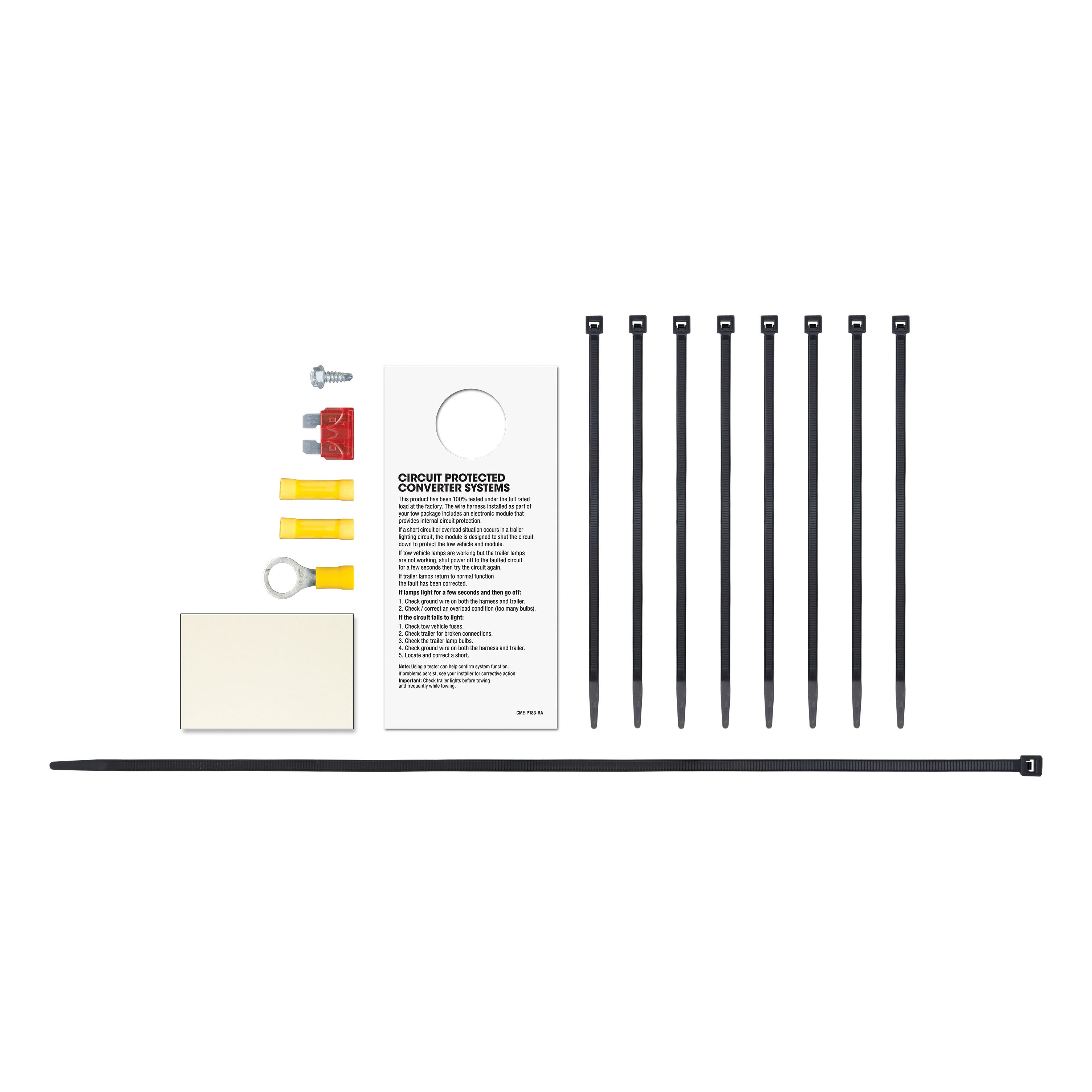
- If no suitable point exists, drill a 3/32" hole and secure the white wire using the provided eyelet and screw.
-
Mount the Converter Box:
- Use the provided double-sided tape to adhere the black converter box to the vehicle frame.
- Secure any loose parts of the T-Connector with the supplied cable ties.
-
Route the Power Wire:
- Route the black power wire from the battery as detailed in the included CME-PCL-INS sheet.
- If applicable, pass the black wire through any rubber grommet in the trunk area to reach the black converter.
-
Reassemble the Trunk Area:
- Reinstall the threshold, side felt liner, and any other items removed during installation.
-
Store the 4-Flat Connector:
- When not in use, store the 4-flat connector in the rear cargo area.
Safety Notes:
- Warning: Before drilling, ensure there are no hidden items behind or under any surface to prevent vehicle damage and/or personal injury.
Additional Notes:
- If using the converter as a powered module for a two-wire system, the red brake wire must be grounded.
- Use a ring terminal for the battery connection.
- Install a fuse holder with a 10-amp fuse maximum (install the fuse after completing all other steps).
- Attach the ring terminal of the white ground wire to the vehicle body using the provided screw (drill a 3/32" hole if necessary).
- Mount the converter using the provided double-sided tape.
- Disconnect the negative battery (-) cable before wiring the power wire.
- Route the black wire to the positive battery (+) terminal.
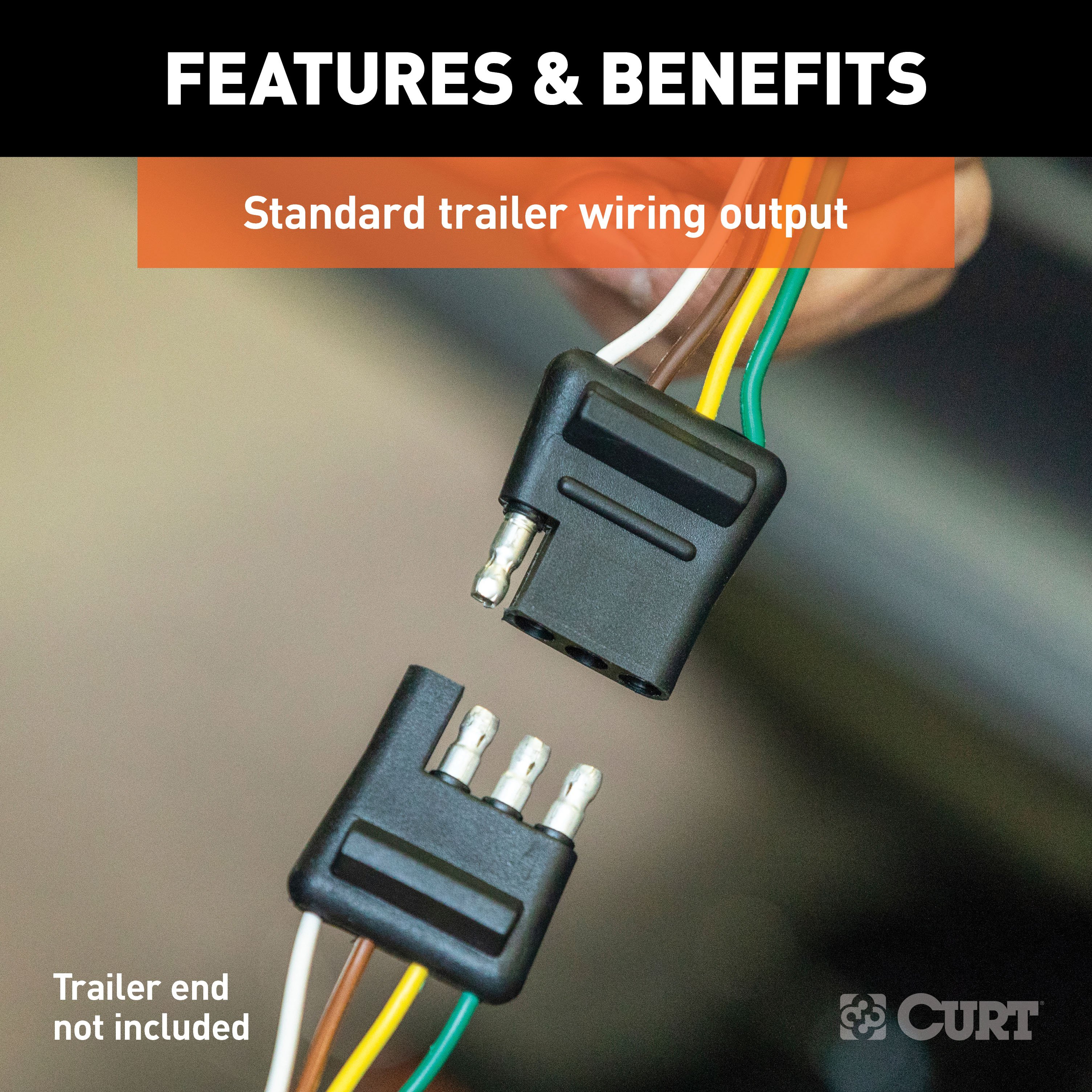
- Wire color codes:
- Green: Right turn
- Red: Brake
- Yellow: Left turn
- Brown: Taillight
Installation Instructions for Cadillac CTS and CTS-V
Part Number:
- 56043
Tools Required:
- 3/32" drill bit (if necessary)
Step-by-Step Instructions:
-
Access the Vehicle's Wiring:
- Open the trunk and remove the plastic threshold and felt trunk liner on the driver's side to locate the vehicle's wiring harness.
-
Disconnect the Wiring Harness:
- Identify the vehicle wiring harness connection point that matches the T-Connector ends.
- Carefully separate the vehicle wiring harness, ensuring the locking tabs remain intact.
-
Install the T-Connector:
- Insert the T-Connector between the separated vehicle harness connectors.
- Ensure the housings are fully inserted without damaging the locking tabs.
-
Establish Ground Connection:
- Find a suitable grounding point near the connector, such as an existing screw with a nut in the vehicle's frame.
- If no suitable point exists, drill a 3/32" hole and secure the white wire using the provided eyelet and screw.
-
Mount the Converter Box:
- Use the provided double-sided tape to adhere the black converter box to the vehicle frame.
- Secure any loose parts of the T-Connector with the supplied cable ties.
-
Route the Power Wire:
- Route the black power wire from the battery as detailed in the included CME-PCL-INS sheet.
- If applicable, pass the black wire through any rubber grommet in the trunk area to reach the black converter.
-
Reassemble the Trunk Area:
- Reinstall the threshold, side felt liner, and any other items removed during installation.
-
Store the 4-Flat Connector:
- When not in use, store the 4-flat connector in the rear cargo area.
Safety Notes:
- Warning: Before drilling, ensure there are no hidden items behind or under any surface to prevent vehicle damage and/or personal injury.
Additional Notes:
- If using the converter as a powered module for a two-wire system, the red brake wire must be grounded.
- Use a ring terminal for the battery connection.
- Install a fuse holder with a 10-amp fuse maximum (install the fuse after completing all other steps).
- Attach the ring terminal of the white ground wire to the vehicle body using the provided screw (drill a 3/32" hole if necessary).
- Mount the converter using the provided double-sided tape.
- Disconnect the negative battery (-) cable before wiring the power wire.
- Route the black wire to the positive battery (+) terminal.
Wire Color Codes:
- Green: Right turn
- Red: Brake
- Yellow: Left turn
- Brown: Taillight
Important Information:
- Attention: This is a summary of the installation procedure. For complete installation instructions, including diagrams and detailed information from the manufacturer, please download the full installation PDF.
- For technical support and assistance, our team of experts is available to help. You can reach our tech support by visiting www.trailerjacks.com or calling 877-869-6690.
- Warranty Information: For complete warranty instructions, please download the full installation PDF.


