Product Details
- Brand: Curt
- Model: 13172 56208-CH2461
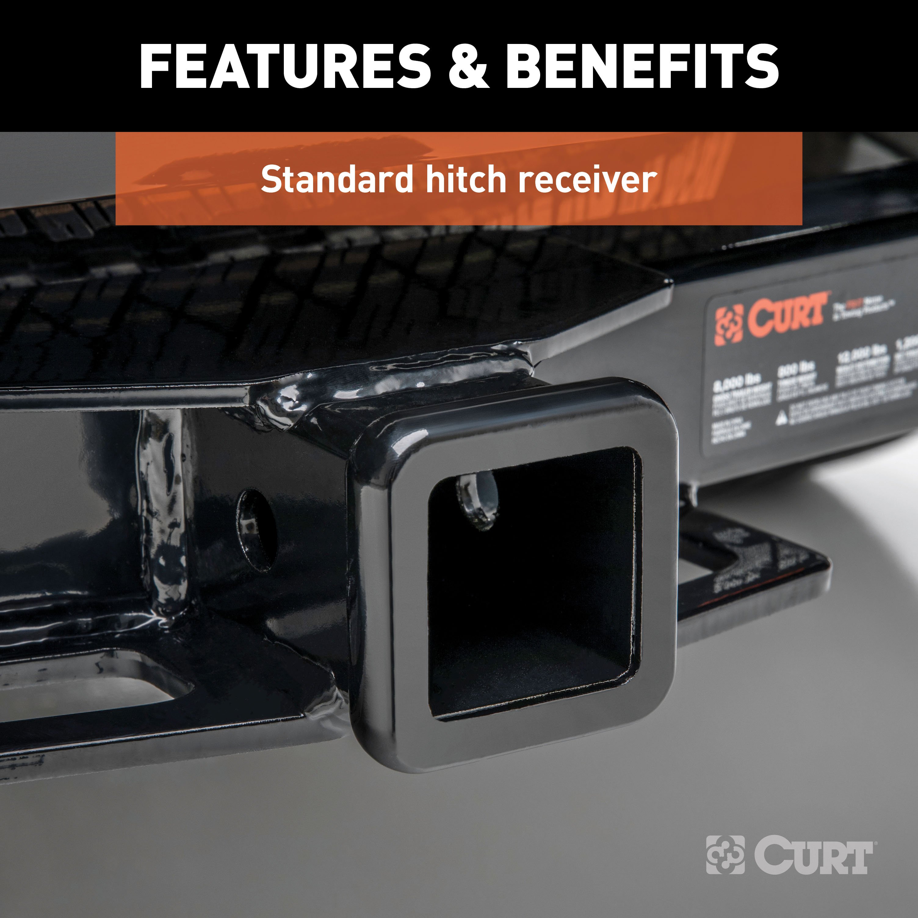
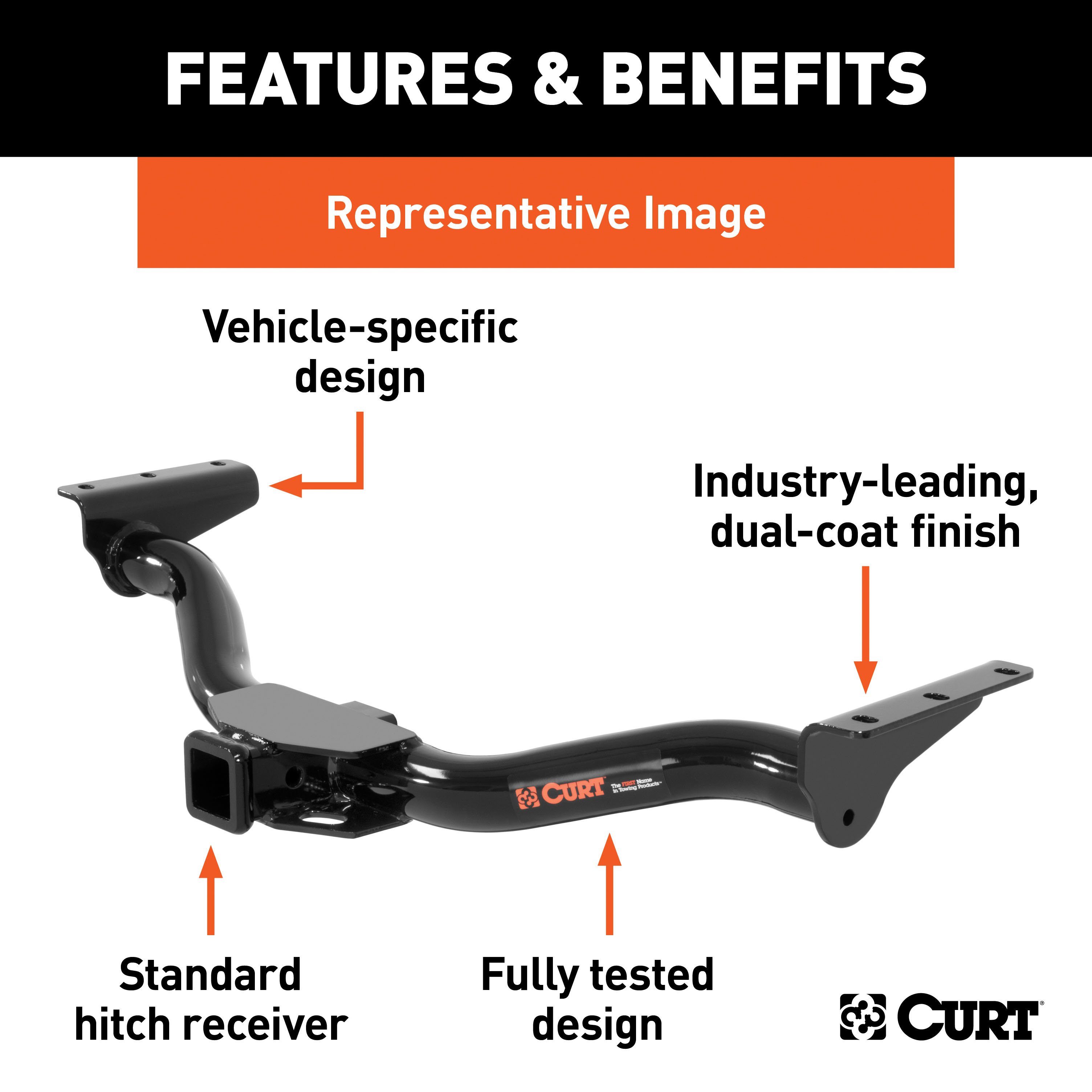
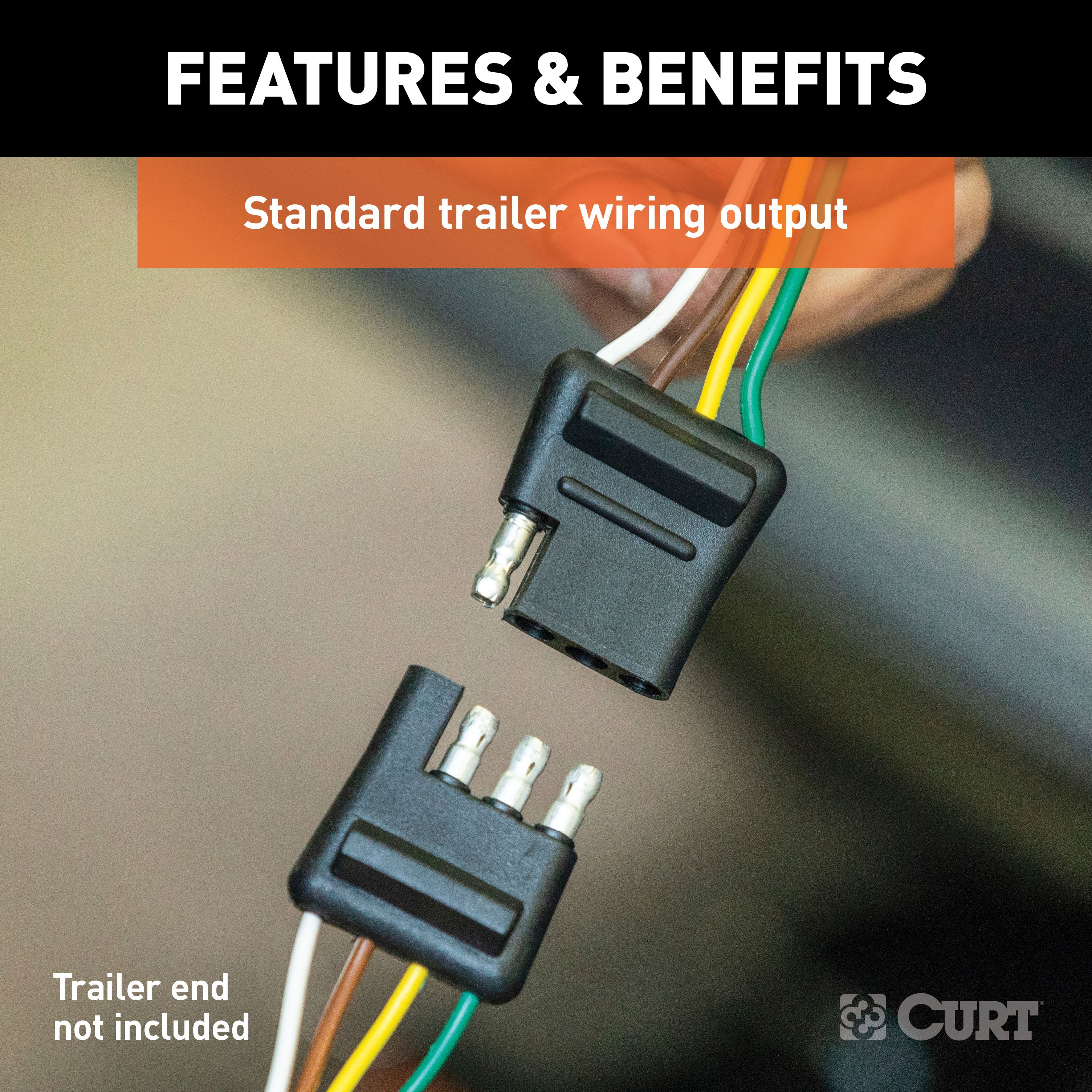
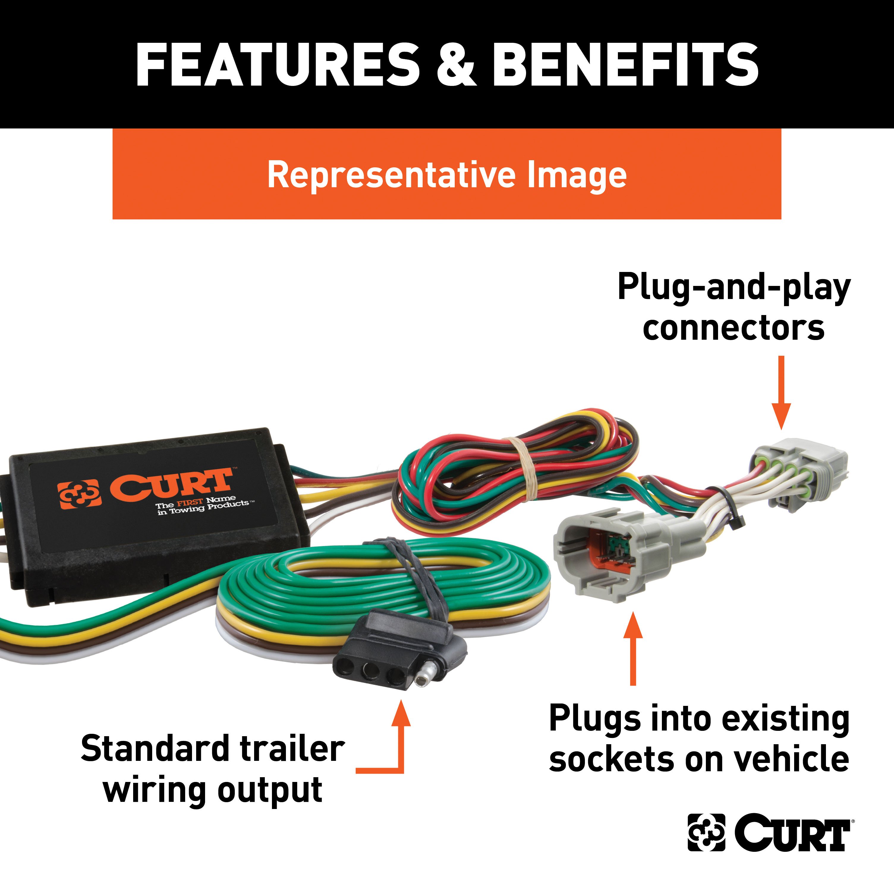
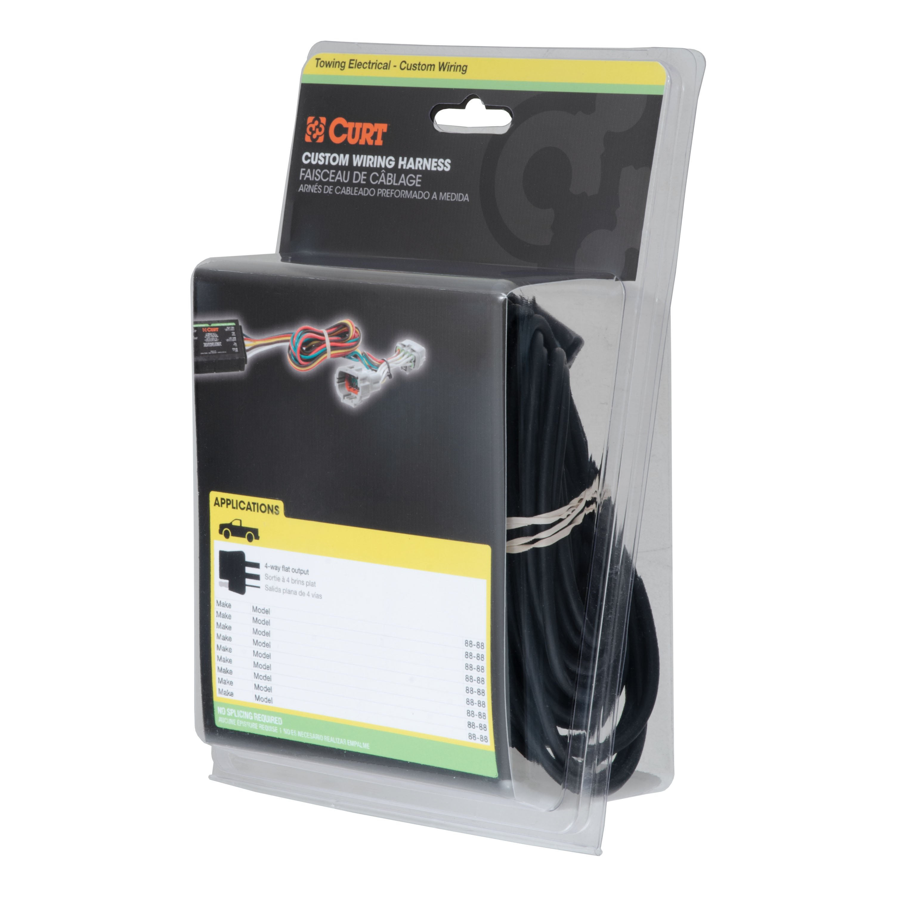
- Includes: Class 3 Trailer Tow Hitch, Custom Wiring Harness
Compatibility Chart
Get Expert Help
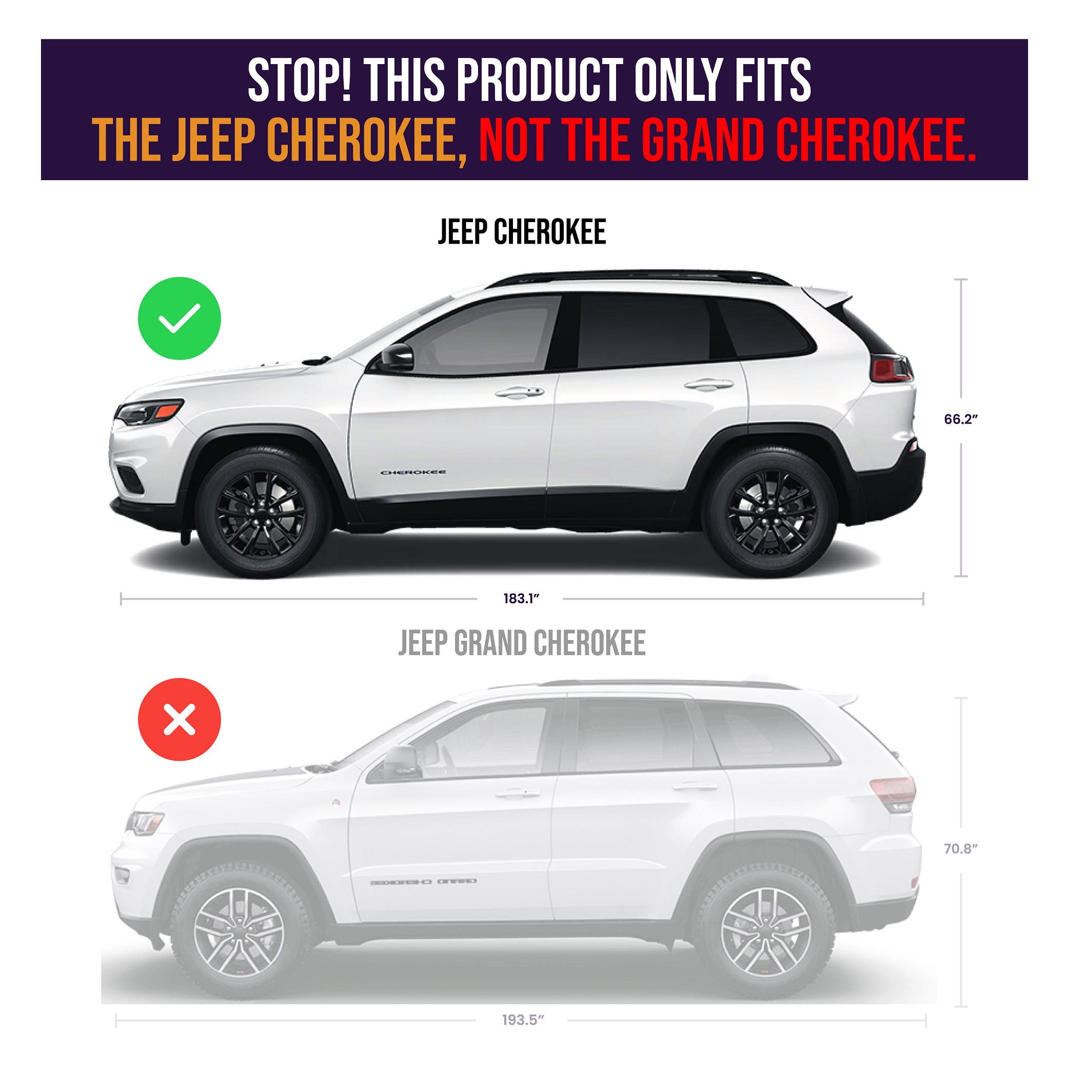
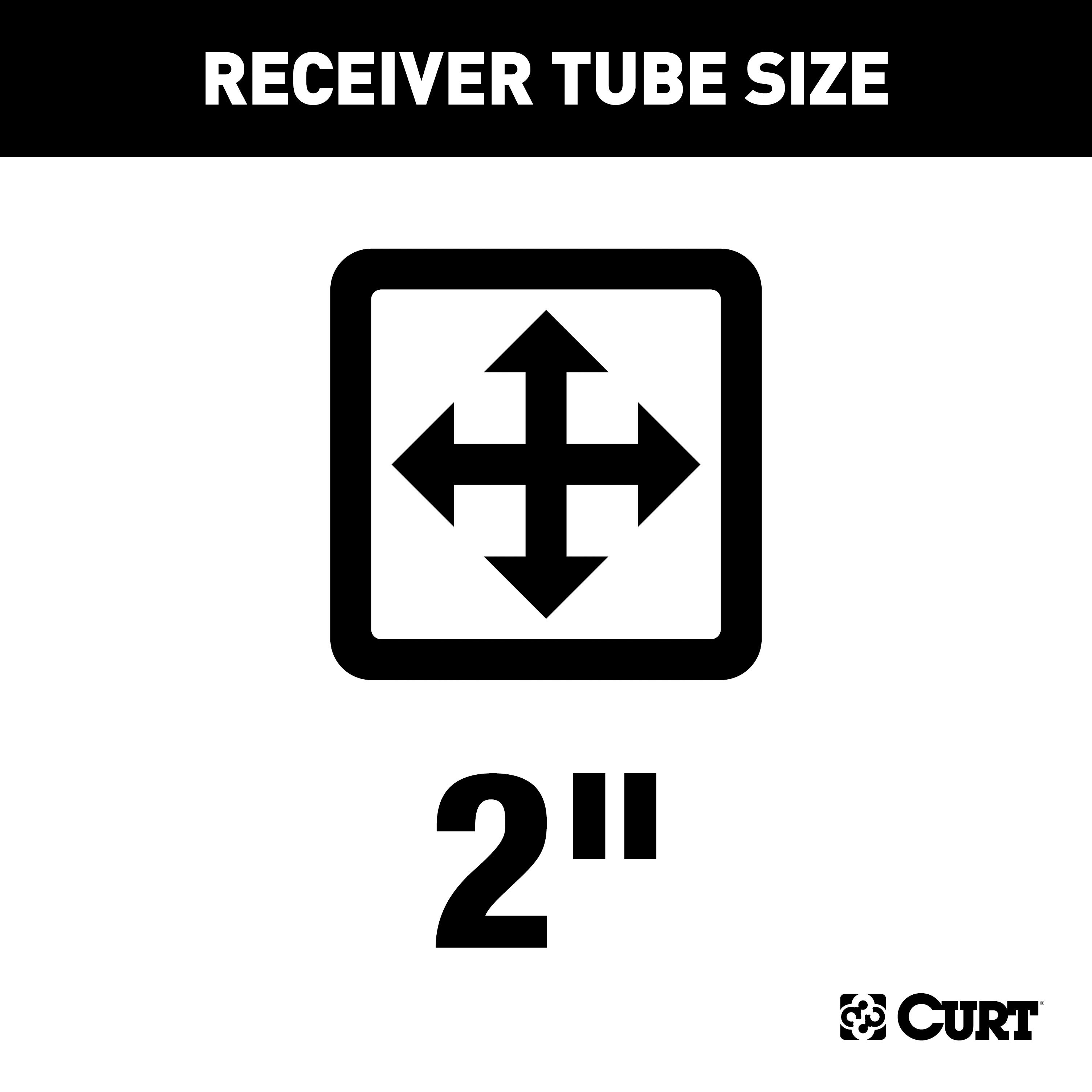
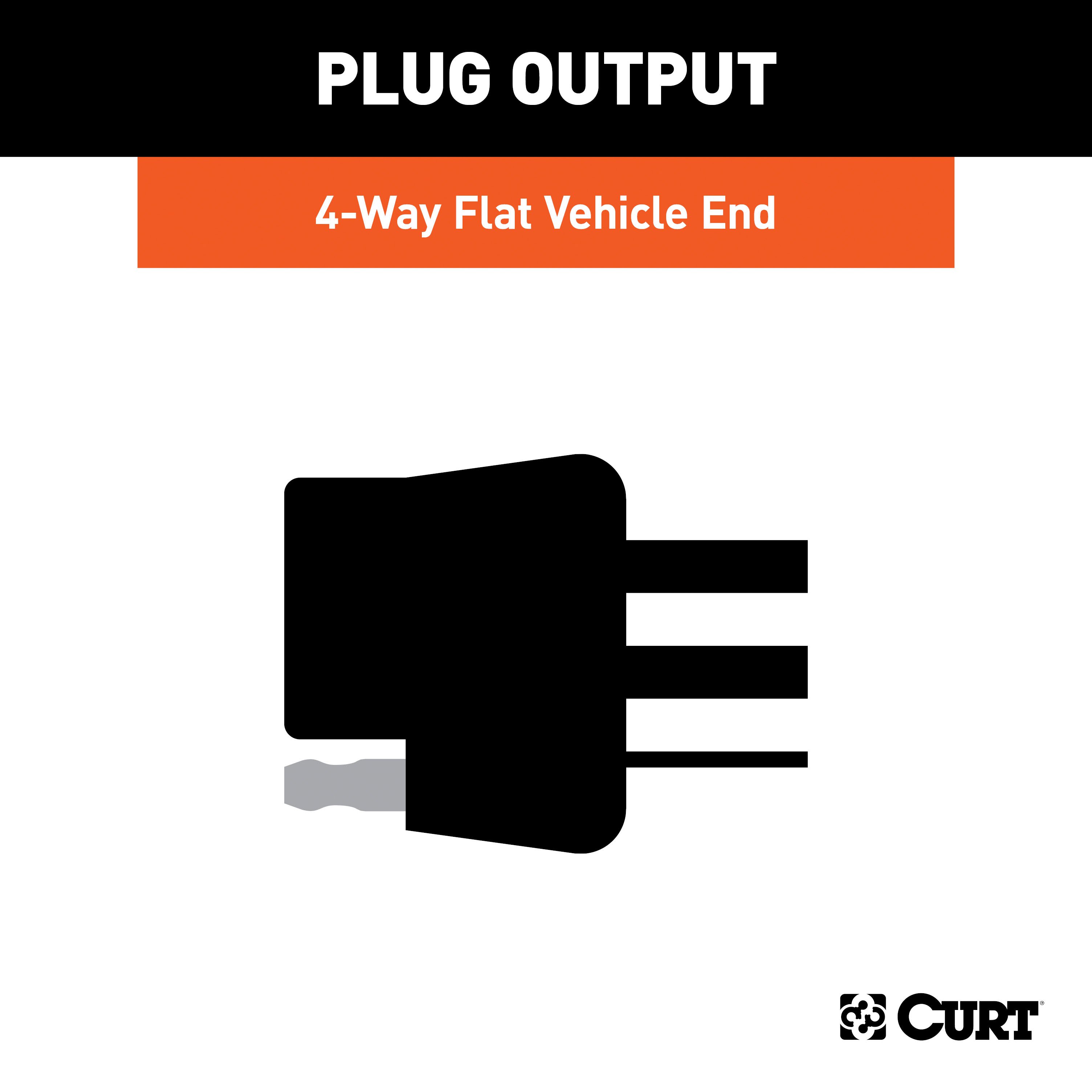
For 2014-2018 Jeep Cherokee Trailer Hitch + Wiring 4 Pin Fits All Models Curt 13172 56208 2 inch Tow Receiver Install Notes
Installation Instructions for Jeep Cherokee (2014-Present)
Part Numbers:
- 13172
Tools Required:
- Ratchet
- Torque Wrench
- 8mm Socket
- 10mm Socket
- 13mm Socket
- 21mm Socket
- 3/4" Socket
- 9" Socket Extension
- Cut-Off Wheel
- Tape Measure
- Safety Glasses
Step-by-Step Instructions:
Step 1: Lower the exhaust
- Remove the two bolts connecting the exhaust hanger bracket to the frame using a 13mm socket (both sides).
- Support the exhaust from underneath during installation.
Step 2: Temporarily remove the fascia support
- Remove the four screws securing the fascia support using an 8mm socket.
- Press down on the tabs to release and remove the support.
Step 3: Trim the center of the fascia
- Trim the center of the fascia roughly 3 1/2" by 4 3/4" using a cut-off wheel.
- Note: Removing the fascia is not required for trimming.
Step 4: Remove existing hardware (Trailhawk models only)
- Remove the rear vertical and horizontal M14 bolts from the frame using a 21mm socket. Save the bolts for reassembly.
- If a wire is present on the passenger-side frame rail, unfasten it by pulling the retainer out of the frame. Let the wire hang below the frame rail.
Step 5: Remove the frame plugs
- Remove the square rubber plugs from the frame to expose the access holes on both sides.
Step 6: Fishwire the hardware
- Fishwire the rear and side hardware through the access holes in the frame.
- Reverse fishwire the remaining hardware into the access holes.
- Note: On Trailhawk models, only reverse fishwire hardware and the M14 bolts removed in Step 4 are used.
Step 7: Position the hitch
- Raise the hitch into position and loosely secure it with the hardware. Be careful not to push the hardware back inside the frame.
- Note: Trimming of the exhaust bezel may be required on some models. Check fitment around the hitch, and trim additional areas if necessary. Seam foam may also need to be trimmed.
Step 8: Torque the hardware
- Torque all 1/2" hardware to 110 lb-ft.
- Torque all M14 hardware to 139 lb-ft (if present).
Step 9: Reinstall components
- Reinstall the fascia support removed in Step 2.
- Raise the exhaust back to its original position and secure the exhaust bracket bolts.
- If a wire was removed in Step 4, reattach it to its original position.
Hardware List:
- (6) 1/2"-13 x 1-1/2" Carriage Bolt, Grade 8 (#10-10287)
- (6) 1/2"-13 Serrated-Flange Nut (#20-00062)
- (6) .250 x 1.00 x 3.00" Square Hole Spacer (#CM-SP6)
- (1) 1/2" Fishwire Tool (#1_2 FISHWIRE)
Safety Notes:
- Safety glasses must be worn during installation.
- Periodically check the hitch to ensure all fasteners are tight and structural components are sound.
- Do not exceed the vehicle manufacturer’s recommended towing capacity.
Specifications:
- Weight Carrying Capacity: 5,000 lbs trailer weight, 750 lbs tongue weight
- Weight Distribution Capacity: 6,000 lbs trailer weight, 750 lbs tongue weight
- Installation Time: 50 minutes (Professional), 100 minutes (Novice)
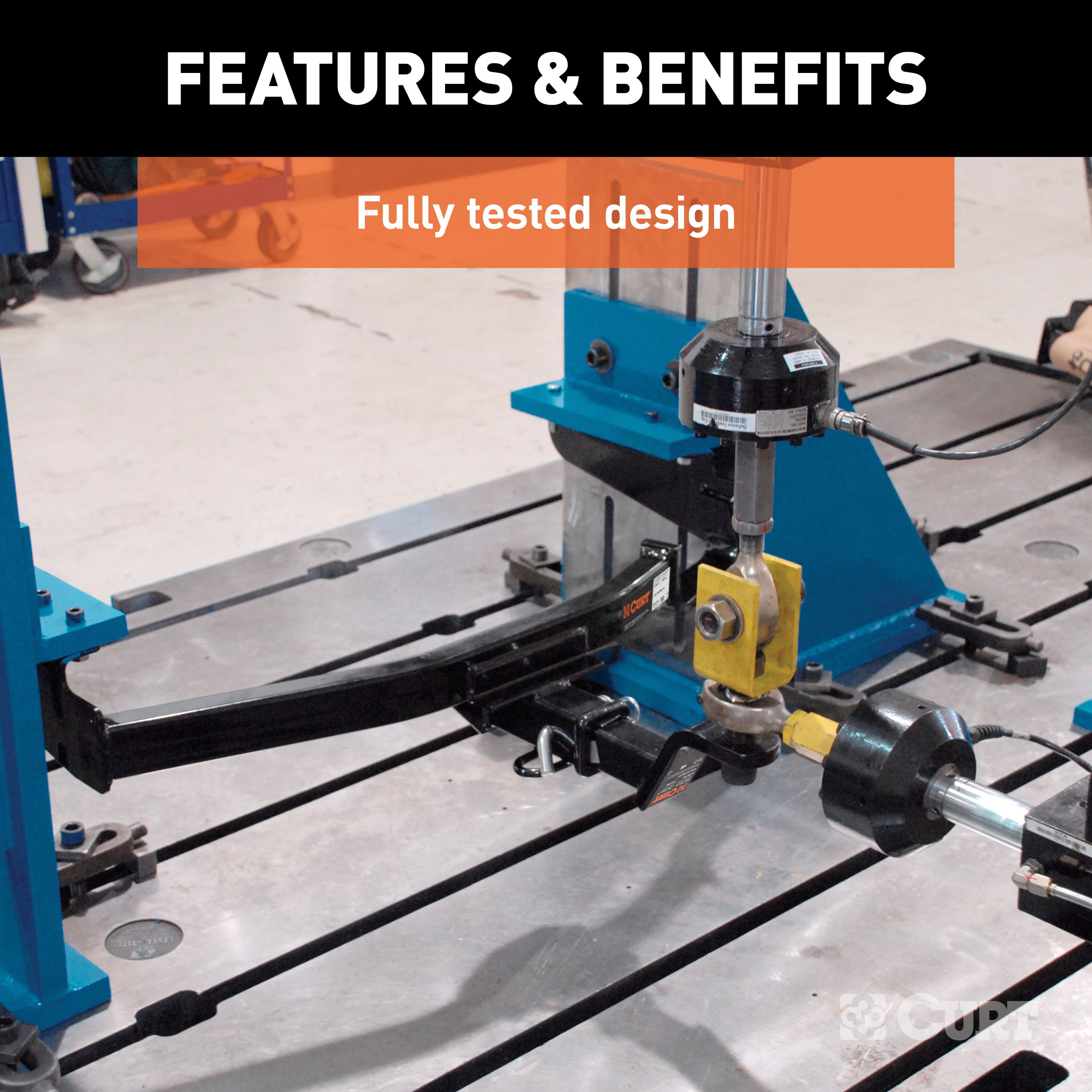
- Compliance: SAE J684, VESC Regulation V-5
Additional Notes:
- No drilling is required.
- Fascia trimming is required.
- Fishwiring and reverse fishwiring are necessary for hardware installation.
- Torque specifications must be strictly followed.
- For installation questions, contact technical support at 1-877-287-8634.
Installation Instructions for Jeep Cherokee (2014-Present)
Part Numbers:
- 13172
Tools Required:
- Ratchet
- Torque Wrench
- 8mm Socket
- 10mm Socket
- 13mm Socket
- 21mm Socket
- 3/4" Socket
- 9" Socket Extension
- Cut-Off Wheel
- Tape Measure
- Safety Glasses
Step-by-Step Instructions:
Step 1: Lower the exhaust
- Remove the two bolts connecting the exhaust hanger bracket to the frame using a 13mm socket (both sides).
- Support the exhaust from underneath during installation.
Step 2: Temporarily remove the fascia support
- Remove the four screws securing the fascia support using an 8mm socket.
- Press down on the tabs to release and remove the support.
Step 3: Trim the center of the fascia
- Trim the center of the fascia roughly 3 1/2" by 4 3/4" using a cut-off wheel.
- Note: Removing the fascia is not required for trimming.
Step 4: Remove existing hardware (Trailhawk models only)
- Remove the rear vertical and horizontal M14 bolts from the frame using a 21mm socket. Save the bolts for reassembly.
- If a wire is present on the passenger-side frame rail, unfasten it by pulling the retainer out of the frame. Let the wire hang below the frame rail.
Step 5: Remove the frame plugs
- Remove the square rubber plugs from the frame to expose the access holes on both sides.
Step 6: Fishwire the hardware
- Fishwire the rear and side hardware through the access holes in the frame.
- Reverse fishwire the remaining hardware into the access holes.
- Note: On Trailhawk models, only reverse fishwire hardware and the M14 bolts removed in Step 4 are used.
Step 7: Position the hitch
- Raise the hitch into position and loosely secure it with the hardware. Be careful not to push the hardware back inside the frame.
- Note: Trimming of the exhaust bezel may be required on some models. Check fitment around the hitch, and trim additional areas if necessary. Seam foam may also need to be trimmed.
Step 8: Torque the hardware
- Torque all 1/2" hardware to 110 lb-ft.
- Torque all M14 hardware to 139 lb-ft (if present).
Step 9: Reinstall components
- Reinstall the fascia support removed in Step 2.
- Raise the exhaust back to its original position and secure the exhaust bracket bolts.
- If a wire was removed in Step 4, reattach it to its original position.
Hardware List:
- (6) 1/2"-13 x 1-1/2" Carriage Bolt, Grade 8 (#10-10287)
- (6) 1/2"-13 Serrated-Flange Nut (#20-00062)
- (6) .250 x 1.00 x 3.00" Square Hole Spacer (#CM-SP6)
- (1) 1/2" Fishwire Tool (#1_2 FISHWIRE)
Safety Notes:
- Safety glasses must be worn during installation.
- Periodically check the hitch to ensure all fasteners remain tight and structural components remain sound.
- Do not exceed the vehicle manufacturer’s recommended towing capacity.
Specifications:
- Weight Carrying Capacity: 5,000 lbs trailer weight, 750 lbs tongue weight
- Weight Distribution Capacity: 6,000 lbs trailer weight, 750 lbs tongue weight
- Installation Time: 50 minutes (Professional), 100 minutes (Novice)
- Compliance: SAE J684, VESC Regulation V-5
Additional Notes:
- No drilling is required.
- Fascia trimming is required.
- Fishwiring and reverse fishwiring are necessary for hardware installation.
- Torque specifications must be strictly followed.
- For installation questions, please refer to the installation PDF.
Warranty Information:
- The product comes with a 5-year warranty covering defects in materials and workmanship.
- For complete warranty instructions, please download the full installation PDF.
Technical Support:
For technical support and assistance, our team of experts is available to help. You can reach our tech support by visiting www.trailerjacks.com or calling 877-869-6690.
End of Instructions
Installation Instructions for Jeep Cherokee
Part Numbers:
- 56208
Wiring Access Location:
- S1: Behind driver-side taillight housing
- S2: Behind passenger-side taillight housing
Tools Required:
- Phillips screwdriver
- T-15 Torx bit
- T-27 Torx bit
Step-by-Step Process:
Step 1: Prepare the Trunk Area
- Open the tailgate and remove the two cargo-tie down fasteners on each side of the vehicle.
- Remove the storage holder on the driver side.
- Lift the trunk floor cover and remove all items stored under it.
- Remove the two Phillips screws securing the spare tire surround.
Step 2: Remove the Rear Scuff Panel
- Using a T-15 Torx, remove the screws securing the cargo-tie downs to the scuff panel.
- Pull the scuff panel out from the bottom and lift upward to remove it.
Step 3: Remove the Driver-Side Taillight
- Using a T-27 Torx bit, remove the two screws securing the taillight housing.
- Carefully pull the taillight housing rearward to remove it, ensuring not to damage the alignment tabs.
- Disconnect the wiring harness from the taillight housing, taking care not to damage the locking tabs.
Step 4: Prepare the Grommet
- Locate the grommet behind the taillight where the vehicle wiring passes through from inside the cabin to the taillight.
- Remove the grommet and cut a slit large enough to route the custom wiring harness through.
Step 5: Install the T-Connector on Driver Side
- Route the yellow wire end of the custom wiring harness through the grommet slit and connect it between the separated connectors.
- Ensure all connectors are fully inserted and the locking tabs are secure.
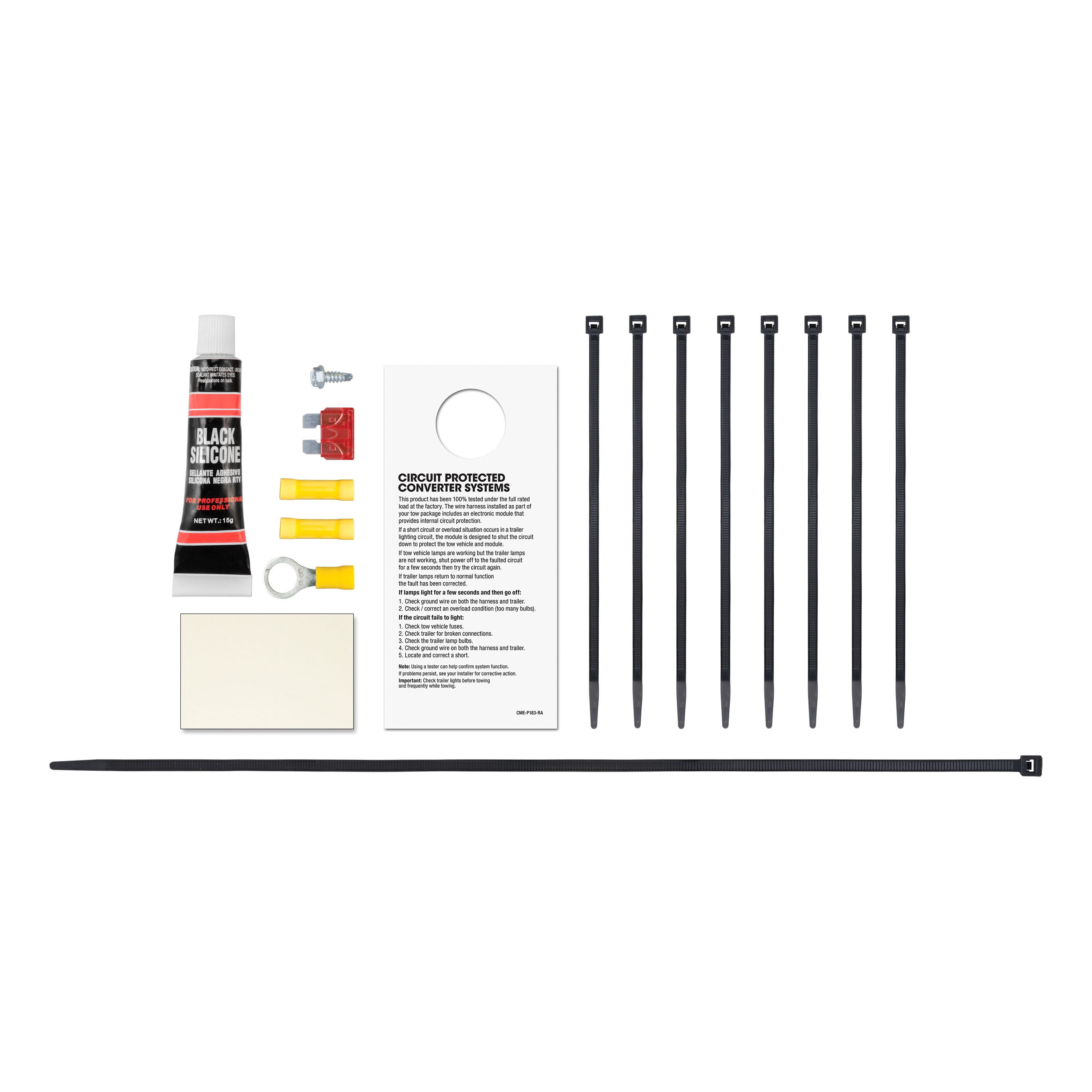
- Reseat the grommet and use the provided sealant to seal the slit and wires.
Step 6: Ground the White Wire
- Locate a suitable grounding point near the connector, such as an existing screw with nut on the vehicle frame.
- If no suitable point exists, drill a 3/32" pilot hole for the provided screw.
- Clean the grounding area of rust, dirt, or paint, and secure the white ground wire using the provided ring terminal and screw.
Step 7: Mount the Converter Box
- Locate a flat, clean surface inside the vehicle near the taillight.
- Adhere the black converter box using the provided double-sided tape.
Step 8: Route the Power Wire
- Route the black power wire from the vehicle battery as shown in the included CME-PCL-INS sheet.
Step 9: Connect the T-Connector on Passenger Side
- Route the green wire end of the custom wiring harness to the passenger side behind the removed scuff panels.
- Repeat Steps 3-5 on the passenger side using the green wire.
Step 10: Position and Use the 4-Flat Connector
- When in use, route the 4-flat connector to the center of the vehicle and out of the trunk.
- When not in use, roll it up and store it in a convenient location inside the trunk.
- Secure loose wires with the provided cable ties.
Step 11: Reassemble and Test
- Reinstall all items removed during the installation process.
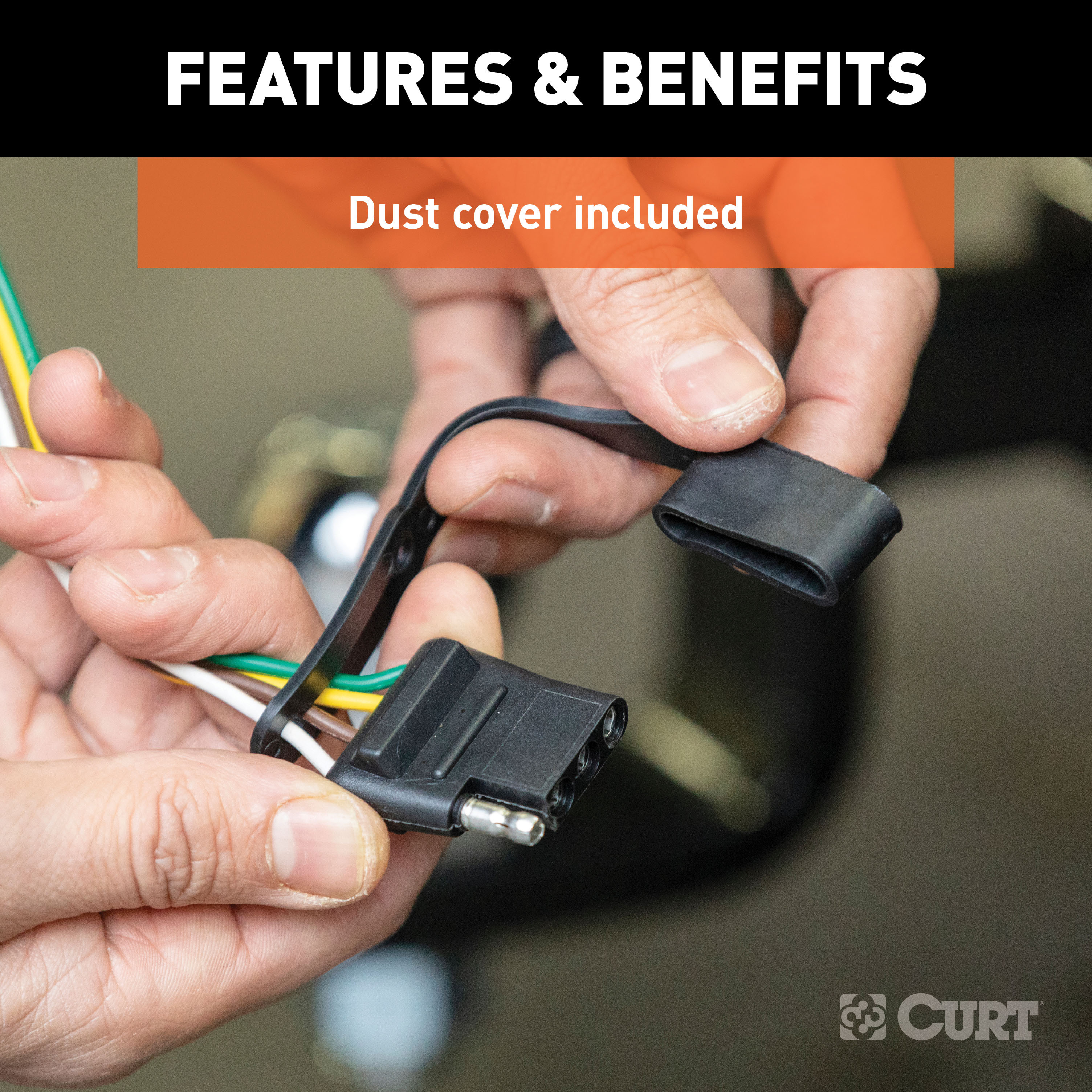
- Install the provided 4-flat dust cover to help prevent corrosion.
- Reconnect the negative battery terminal.
Safety Notes:
- Ensure the battery connection is fuse-protected (10-amp max).
- Do not exceed the product rating or the vehicle lamp load rating.
- Verify proper function using a test light or a properly wired trailer.
- Check for hidden items behind or under surfaces before drilling to avoid damage or injury.
Specifications:
- Signal circuits: 3.0 amps per side
- Tail/running circuits: 6.0 amps total
- Compatible with 12-volt negative ground systems
Attention: This is a summary of the installation procedure. For complete installation instructions, including diagrams and detailed information from the manufacturer, please download the full installation PDF.
For technical support and assistance, our team of experts is available to help. You can reach our tech support by visiting www.trailerjacks.com or calling 877-869-6690.
For complete warranty instructions, please download the full installation PDF.


