Product Details
- Brand: Curt
- Model: 11527 59236-CH660
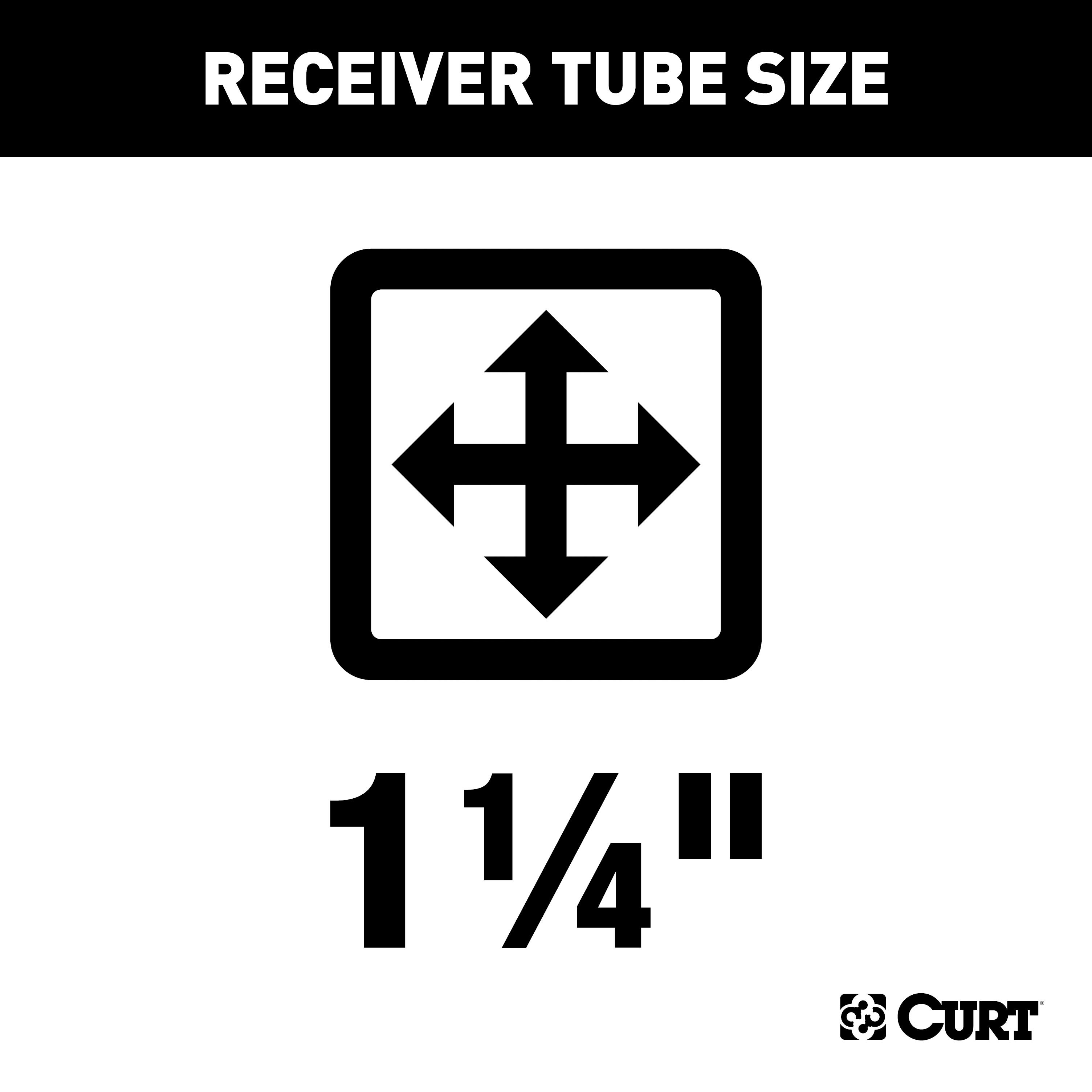
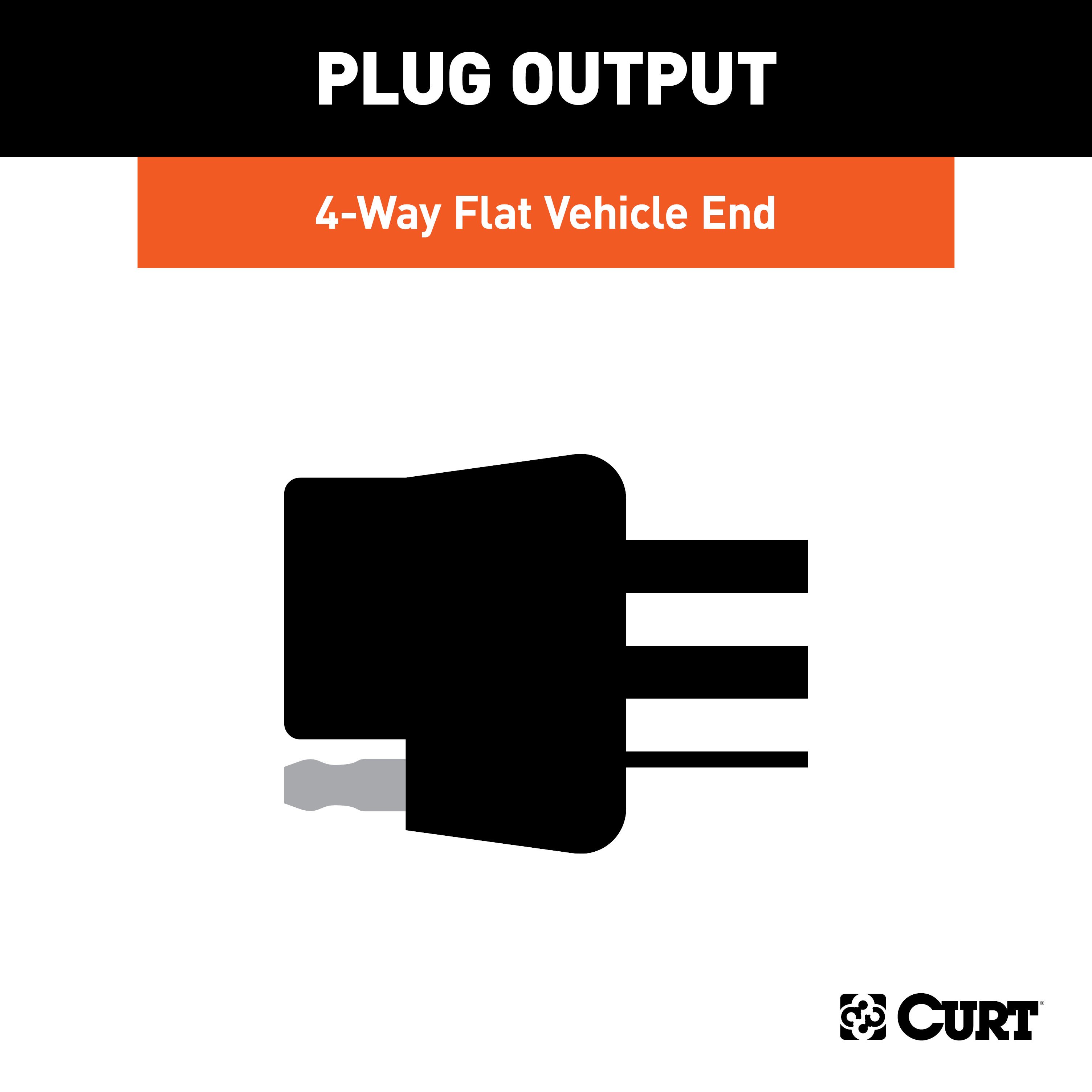
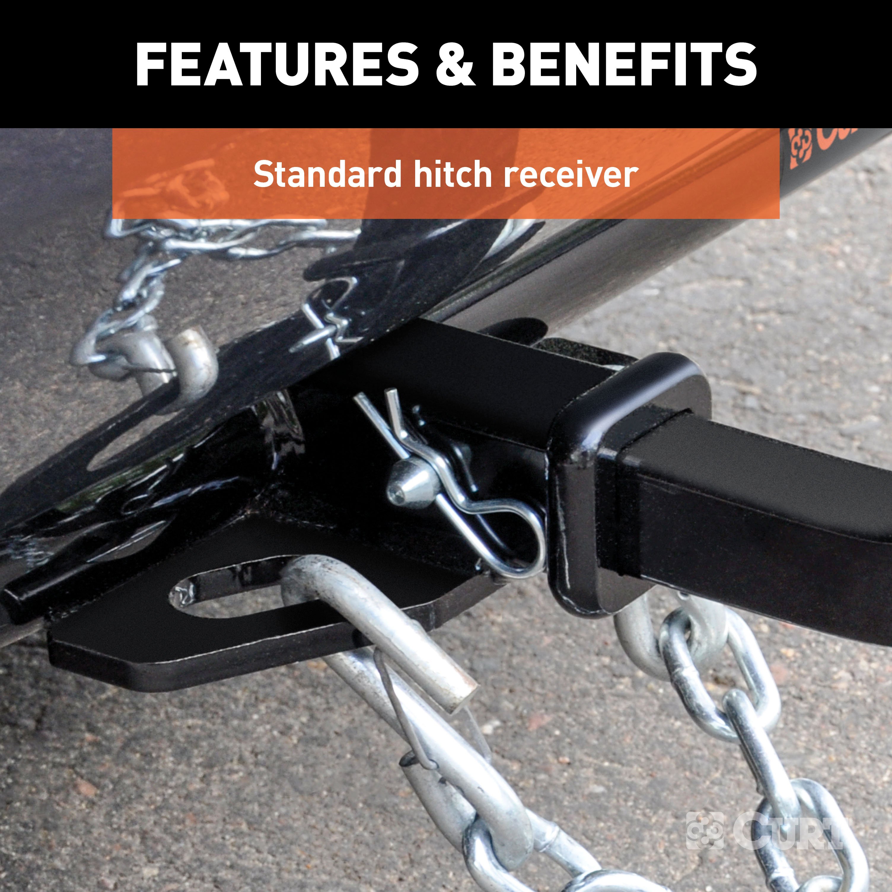
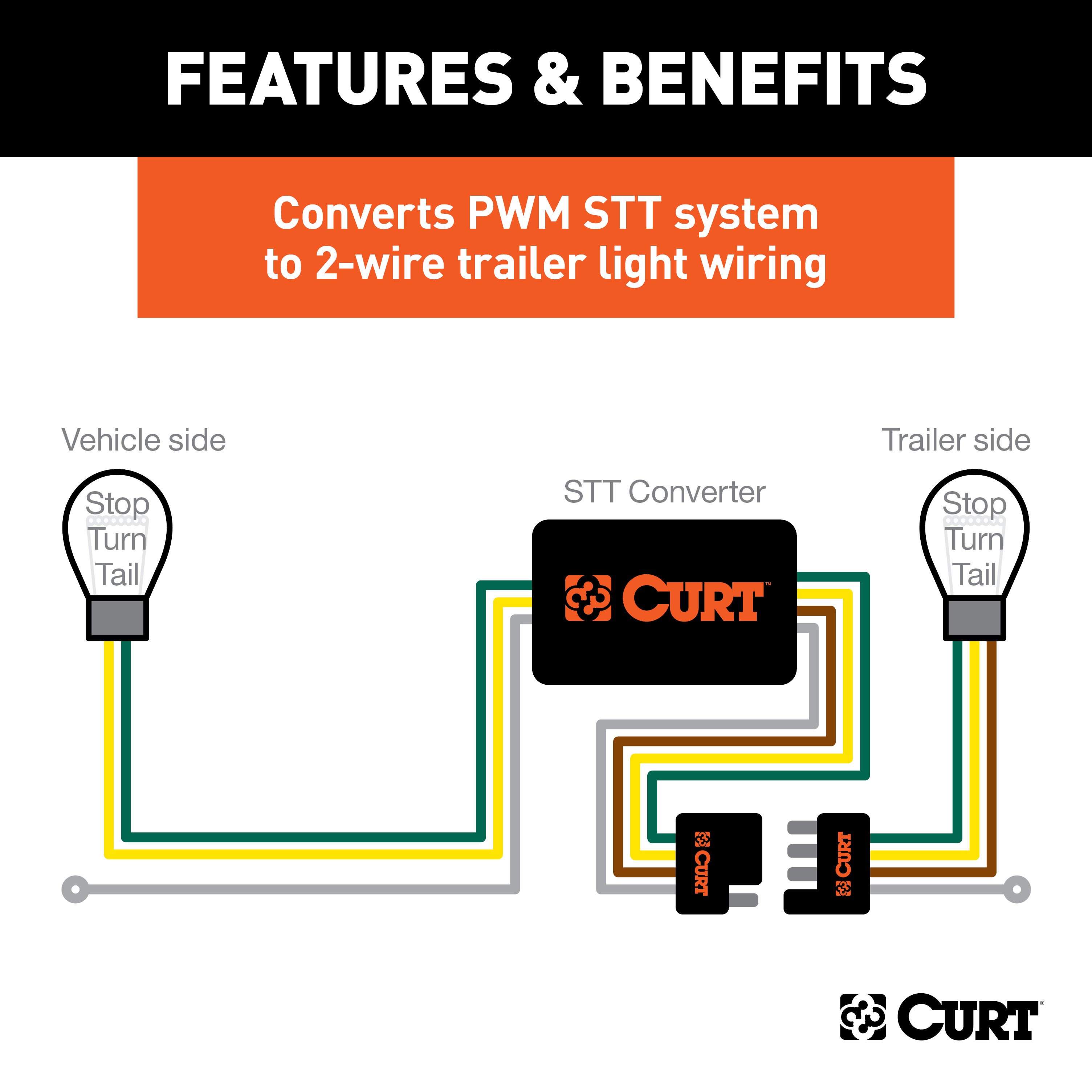
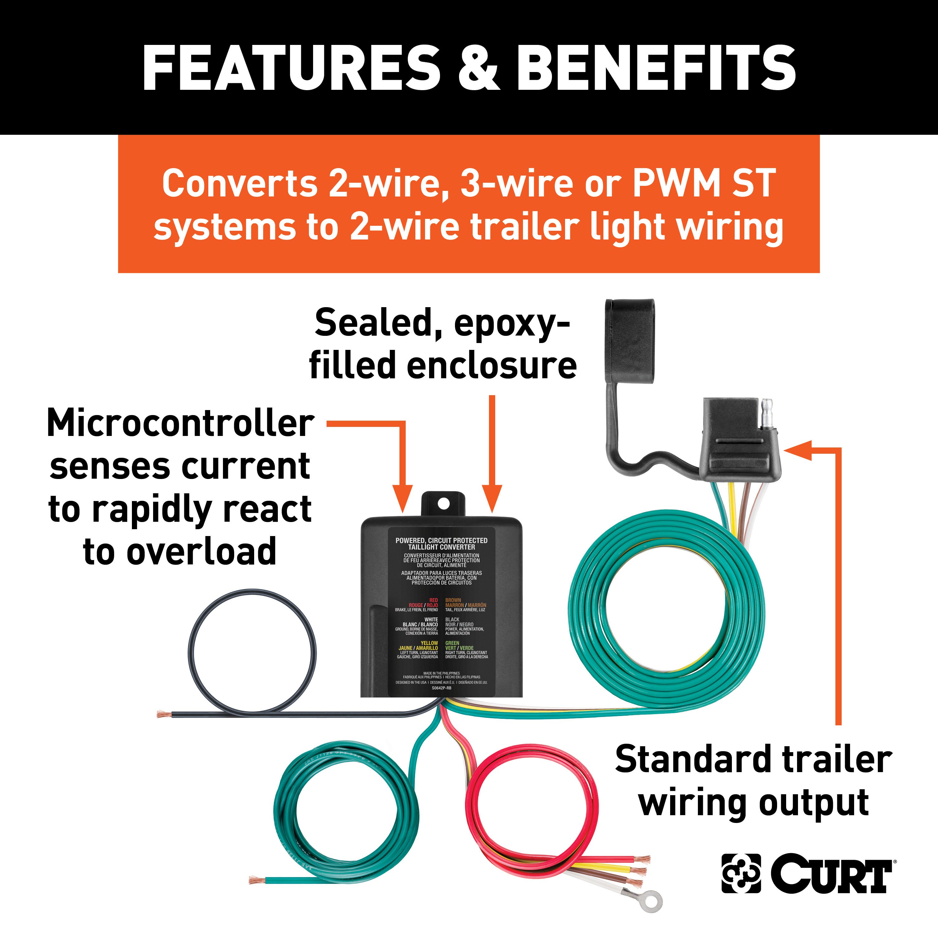
- Includes: Class 1 Trailer Tow Hitch, Multi-Function Taillight Converter Kit
Compatibility Chart
Get Expert Help
For 2015-2016 Chevy Trax Trailer Hitch + Wiring 4 Pin Fits All Models Curt 11527 59236 1-1/4 Tow Receiver Install Notes
Installation Instructions for 2013-Present Buick Encore and Chevrolet Trax Crossover
Part Numbers:
- 11527
Tools Required:
- Ratchet
- Torque Wrench
- 11/16" and 3/4" Sockets
- Socket Extension
- Die Grinder
- Spray Lubricant
- Safety Glasses
Step-by-Step Instructions:
Step 1: Lower Exhaust
- Lower the rear exhaust hangers on both sides of the vehicle.
- For ease of installation, lower the exhaust at the front center location, supporting it from underneath.
- Trim any caulking around the side mounting holes if necessary.
Step 2: Trim Wheel Well Plastic (If Needed)
- On certain model years, trim the wheel well plastic near the frame rails to allow a flush fit for the hitch side plates.
Caution: Avoid cutting into the vehicle brake lines while trimming.
Step 3: Enlarge Access Holes
- Use a die grinder to enlarge the access holes in the vehicle frame to fit the SP2 spacers provided.
Caution: Avoid damaging vehicle brake lines during this step.
Step 4: Fishwire Hardware
- Fishwire the spacers and 7/16" bolts through the access holes and into the bottom mounting holes of the frame.
- Raise the hitch into position and loosely secure it in place using the 7/16" nuts provided.
Step 5: Secure Hitch (Two Scenarios):
a. No Weldnuts in Frame: Fishwire the hardware for the side mounting points through the frame rail and the hitch side plates. Secure all 7/16" hardware.
b. Weldnuts in Frame: Secure the hitch with M12 bolts and 1/2" conical washers in the side mounting points.
Step 6: Torque Hardware
- Torque all 7/16" hardware to 59 ft-lbs.
- Torque all M12-1.25 hardware to 86 ft-lbs.
- Torque all M12-1.75 hardware to 79 ft-lbs.
Step 7: Reinstall Exhaust
- Raise the exhaust hangers back into position.
Hardware List:
- (1) 7/16-14 x 1-1/4" Carriage Bolt (Part Number: 10-102816)
- (2) M12 x 1.25 x 30mm Hex Bolts (Part Number: 10-104194)
- (2) M12 x 1.75 x 30mm Hex Bolts (Part Number: 10-104324)
- (2) 7/16-14 Hex Flange Nuts (Part Number: 20-001036)
- (2) 1/2" Conical Toothed Washers (Part Number: 30-001494)
- (2) .250 x .88 x 2.25" Square Hole Spacers (Part Number: CM-SP2)
- (2) 7/16" Fishwires (Part Number: 7_16 FISHWIRE)
Safety Notes:
- Safety glasses must be worn at all times during installation.
- Periodically check the hitch to ensure all fasteners are tight and structural components are sound.
Specifications:
- Maximum Trailer Weight: 2,000 lbs
- Maximum Tongue Weight: 200 lbs
- Compliant with SAE J684 and V.E.S.C. Regulation V-5
- Designed for use with Ball Mount #45520
- Optional Euro Mounts: #45561 (1-7/8") and #45562 (2" Ball)
Installation Notes:
- Fishwiring and hole enlargement are required.
- Lowering the exhaust is necessary.
- Trimming of wheel well plastic may be required for certain models.
Warning:
All non-trailer loads must be supported by 18050 stabilizing straps. Failure to properly support non-trailer loads will void the product warranty.
Installation Instructions for 2013-Present Buick Encore and Chevrolet Trax Crossover
Part Numbers:
- 11527
Tools Required:
- Ratchet
- Torque Wrench
- 11/16" and 3/4" Sockets
- Socket Extension
- Die Grinder
- Spray Lubricant
- Safety Glasses
Step-by-Step Instructions:
Step 1: Lower Exhaust
- Lower the rear exhaust hangers on both sides of the vehicle.
- For ease of installation, lower the exhaust at the front center location, supporting it from underneath.
- Trim any caulking around the side mounting holes if necessary.
Step 2: Trim Wheel Well Plastic (If Needed)
- On certain model years, trim the wheel well plastic near the frame rails to allow a flush fit for the hitch side plates.
Caution: Avoid cutting into the vehicle brake lines while trimming.
Step 3: Enlarge Access Holes
- Use a die grinder to enlarge the access holes in the vehicle frame to fit the spacers provided.
Caution: Avoid damaging vehicle brake lines during this step.
Step 4: Fishwire Hardware
- Fishwire the spacers and 7/16" bolts through the access holes and into the bottom mounting holes of the frame.
- Raise the hitch into position and loosely secure it in place using the nuts provided.
Step 5: Secure Hitch (Two Scenarios):
a. No Weldnuts in Frame: Fishwire the hardware for the side mounting points through the frame rail and the hitch side plates. Secure all hardware.
b. Weldnuts in Frame: Secure the hitch with bolts and conical washers in the side mounting points.
Step 6: Torque Hardware
- Torque all 7/16" hardware to 59 ft-lbs.
- Torque all M12-1.25 hardware to 86 ft-lbs.
- Torque all M12-1.75 hardware to 79 ft-lbs.
Step 7: Reinstall Exhaust
- Raise the exhaust hangers back into position.
Hardware List:
- (1) 7/16-14 x 1-1/4" Carriage Bolt
- (2) M12 x 1.25 x 30mm Hex Bolts
- (2) M12 x 1.75 x 30mm Hex Bolts
- (2) 7/16-14 Hex Flange Nuts
- (2) 1/2" Conical Toothed Washers
- (2) .250 x .88 x 2.25" Square Hole Spacers
- (2) 7/16" Fishwires
Safety Notes:
- Safety glasses must be worn at all times during installation.
- Periodically check the hitch to ensure all fasteners are tight and structural components are sound.
Specifications:
- Maximum Trailer Weight: 2,000 lbs
- Maximum Tongue Weight: 200 lbs
- Compliant with SAE J684 and V.E.S.C. Regulation V-5
- Designed for use with Ball Mount #45520
- Optional Euro Mounts: #45561 (1-7/8") and #45562 (2" Ball)
Installation Notes:
- Fishwiring and hole enlargement are required.
- Lowering the exhaust is necessary.
- Trimming of wheel well plastic may be required for certain models.
Additional Information:
Attention: This is a summary of the installation procedure. For complete installation instructions, including diagrams and detailed information from the manufacturer, please download the full installation PDF.
Technical Support:
For technical support and assistance, our team of experts is available to help. You can reach our tech support by visiting www.trailerjacks.com or calling 877-869-6690.
Warranty Information:
For complete warranty instructions, please download the full installation PDF.
Warning:
All non-trailer loads must be supported by stabilizing straps. Failure to properly support non-trailer loads will void the product warranty.
Installation Instructions for Wiring Harness with Powered Converter
Part Numbers:
- 59236
Wiring Access Location:
Refer to the wiring location guides based on vehicle type provided in the manual:
SUVs and Vans:
- S1: Behind driver-side taillight housing
- S2: Behind passenger-side taillight housing
- S3: Behind driver-side rear access panel
- S4: Behind passenger-side rear access panel
- S5: Behind driver-side rear bumper
- S6: Behind the center of the rear bumper
- S7: Behind passenger-side rear bumper
- S8: Under rear floor panel
Passenger Cars:
- P1: Behind driver-side taillight housing, outside of the trunk
- P2: Behind passenger-side taillight housing, outside of the trunk
- P3: Behind driver-side taillight housing, inside the trunk
- P4: Behind passenger-side taillight housing, inside the trunk
- P5: Behind driver-side rear bumper
- P6: Behind the center of the rear bumper
- P7: Behind passenger-side rear bumper
Trucks:
- T1: Behind driver-side taillight housing
- T2: Behind passenger-side taillight housing
- T3: Behind driver-side rear bumper
- T4: Behind the center of the rear bumper fascia
- T5: Behind passenger-side rear bumper
Determining Vehicle Wiring Types:
To identify the vehicle wiring type, follow these steps:
- Ensure all lights on the vehicle are off.
- Probe the taillight connectors while they remain connected to the vehicle.
- Use the following wiring descriptions to determine the vehicle type:
Wiring Types:
-
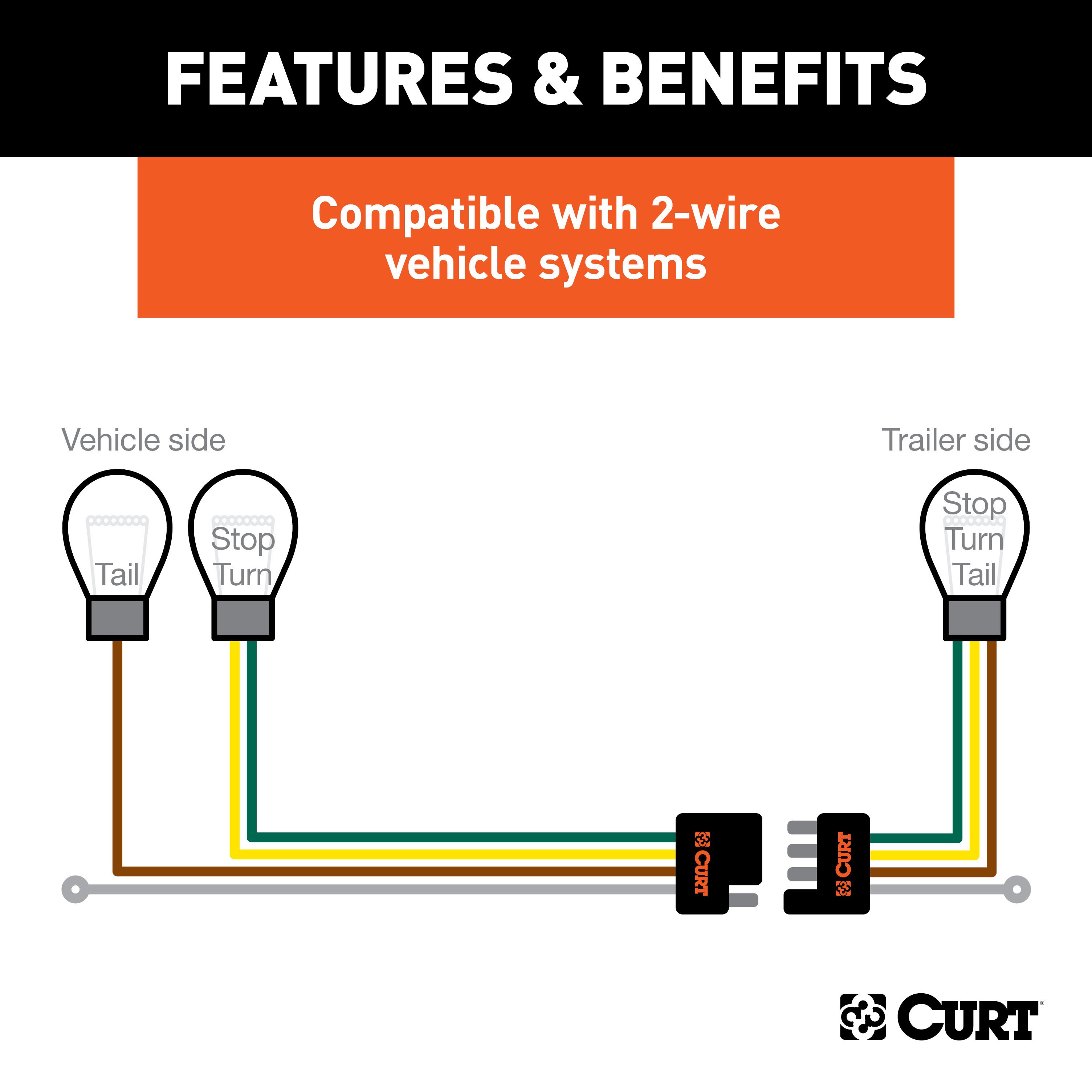
Two-Wire System:
- Combined stop and turn signal with an independent tail signal.
- Indicator: Flashing signal on one side for turn signals; both sides activate for brakes.
-
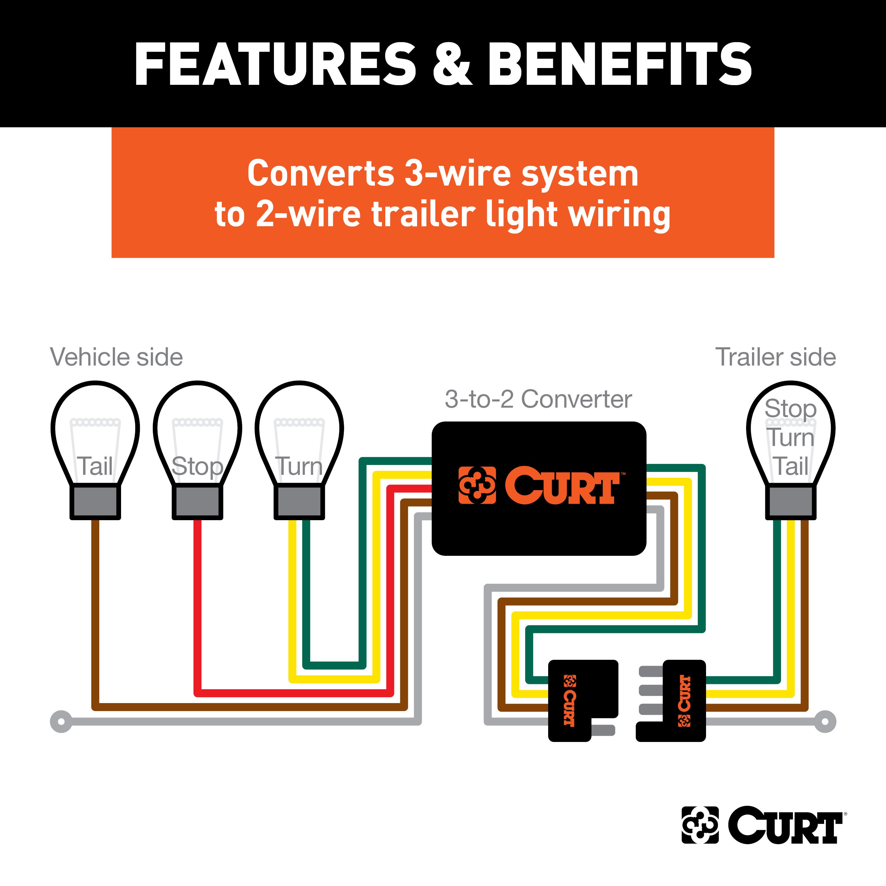
Three-Wire System:
- Independent stop, turn, and tail signals.
- Indicator: Separate wires for turn signals and brake lights.
-
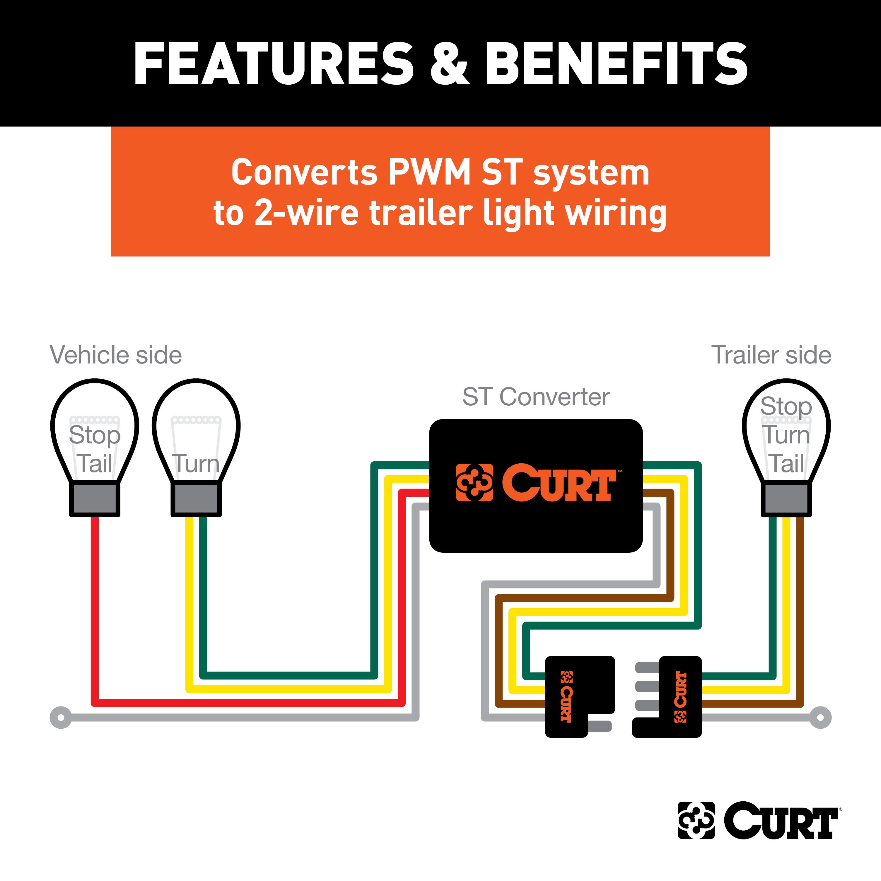
PWM-ST System:
- Combined stop and tail signal with an independent turn signal.
- Indicator: Stop and tail signals use the same wire; separate turn signal wires.
-
PWM-STT System:
- Combined stop, turn, and tail signal.
- Indicator: A single wire serves stop, turn, and tail functions.
Tools Required:
- Test light
- Utility knife
- Electrical tape
- Wire crimper
- Paper
- Wire stripper
- Pen
Step-by-Step Instructions:
-
Locate the Vehicle Battery
- Disconnect the negative battery terminal securely.
-
Identify Vehicle Taillight Wiring
- Use the wiring location guide and instructions for determining the wiring type.
-
Attach the Input Wires
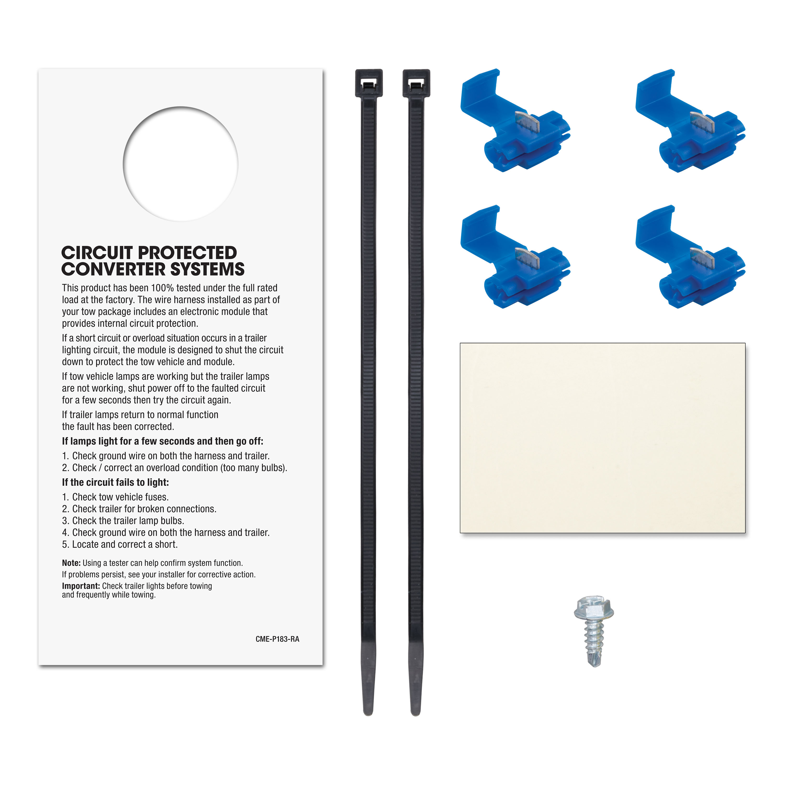
- Match wires using snap locks:
- Green Wire: Splice to the right stop/turn wire.
- Red Wire: Ground with the white wire.
- Yellow Wire: Splice to the left stop/turn wire.
- Brown Wire: Splice to the tail wire.
- Match wires using snap locks:
-
Mount the Converter
- Secure the black converter box near the taillight using the provided double-sided tape.
-
Ground the White Wire
- Use the ring terminal and provided screw to ground the wire at a clean, rust-free location.
-
Route the Power Wire
- Route the black wire to the positive battery terminal, avoiding pinch points or hot components.
-
Install the Fuse
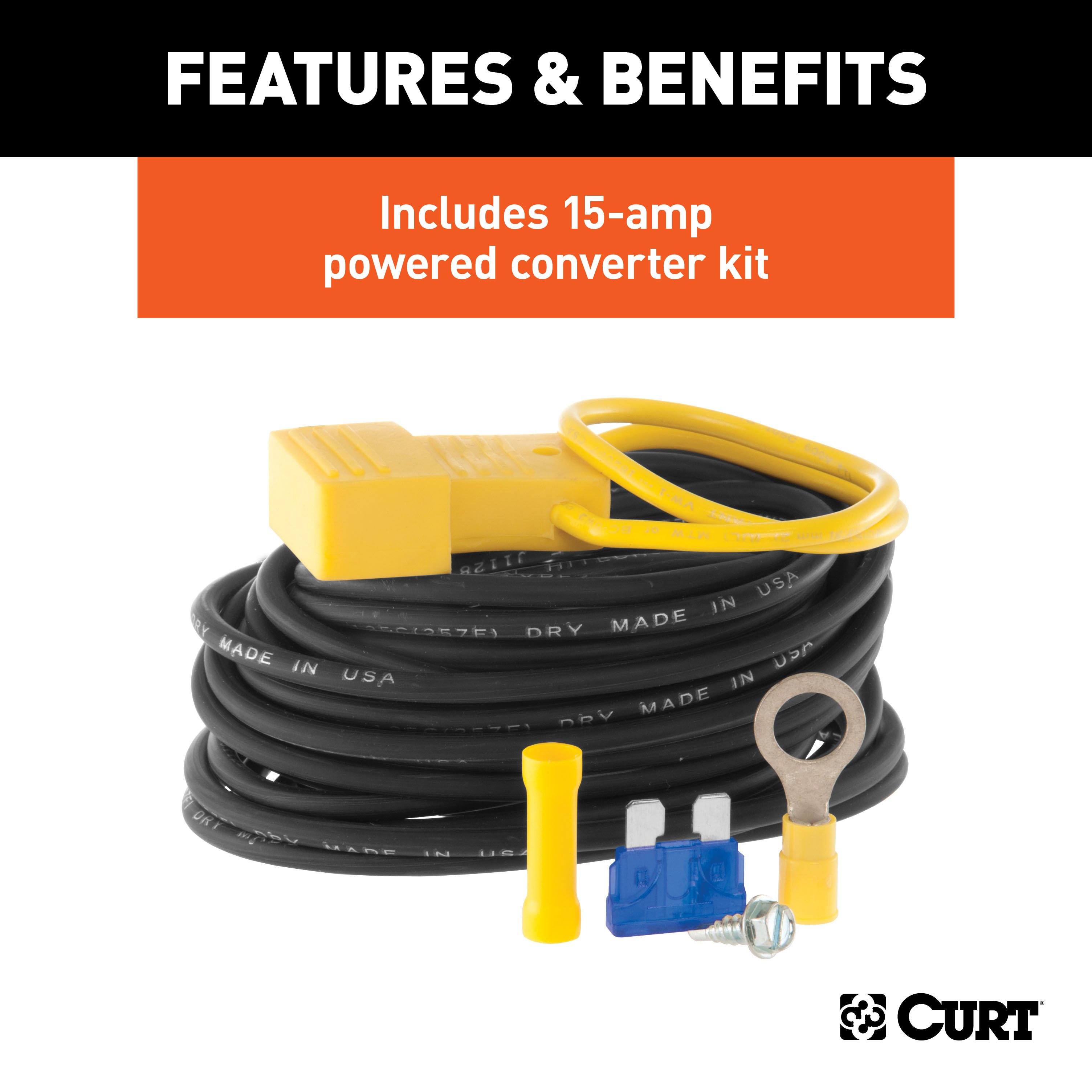
- Add the 15-amp fuse after completing all other steps.
-
Test the System
- Verify turn signals, brake lights, and tail lights using a test light or trailer.
-
Reinstall Components
- Reinstall all removed parts and reconnect the negative battery terminal.
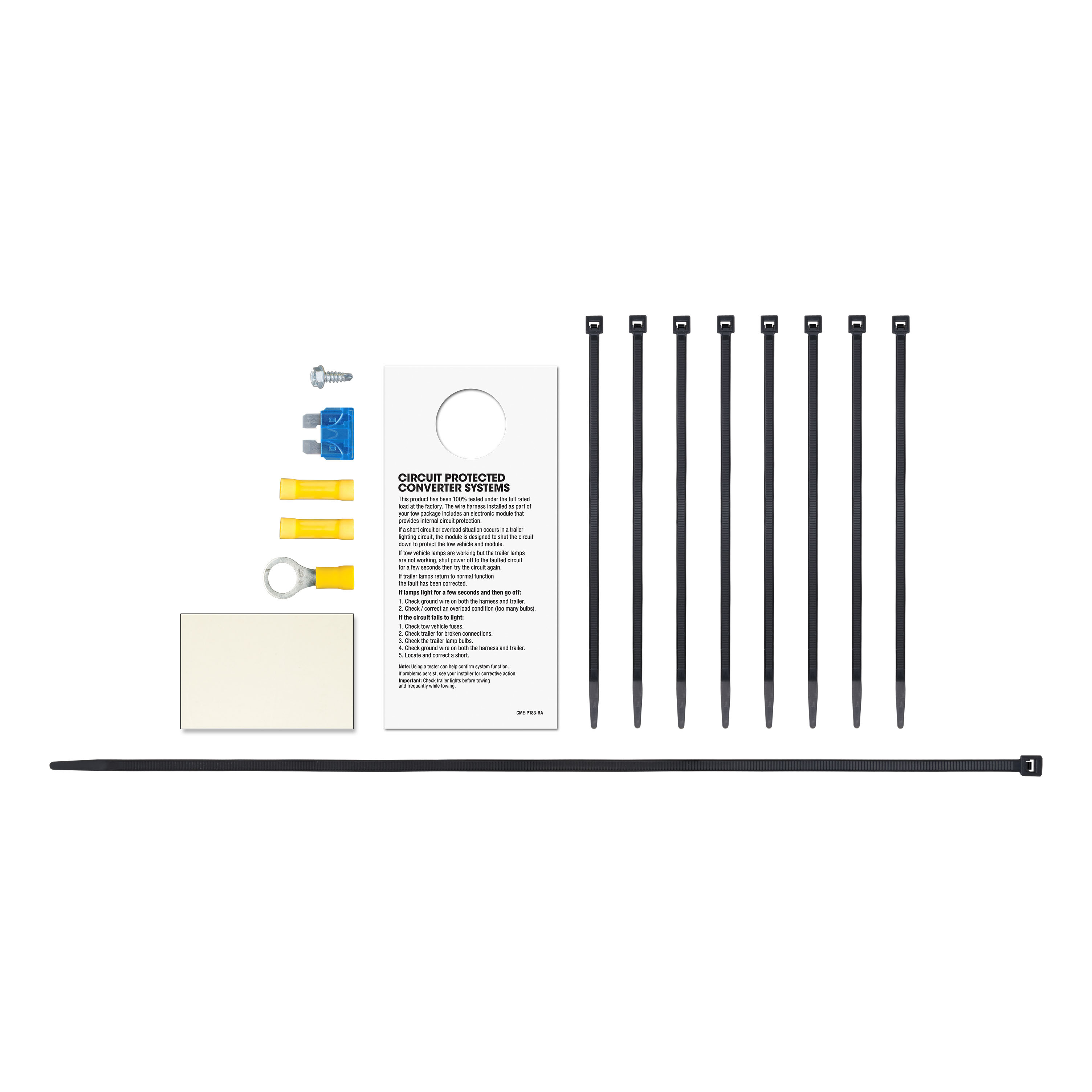
Hardware List:
- Snap locks
- 15-amp fuse and holder
- Ring terminal
- Cable ties
- Double-sided tape
Safety Notes:
- Do not exceed product or tow vehicle lamp load ratings.
- Inspect all wiring periodically for damage or loose connections.
- Avoid drilling without confirming there are no hidden items behind the surface.
Specifications:
- Signal Circuits: 5.0-amps per side
- Tail/Running Circuits: 7.5-amps total
- Compliance: SAE J684
Additional Information:
- Attention: This is a summary of the installation procedure. For complete installation instructions, including diagrams and detailed information from the manufacturer, please download the full installation PDF.
Technical Support:
- For technical support and assistance, our team of experts is available to help. You can reach our tech support by visiting www.trailerjacks.com or calling 877-869-6690.
Warranty:
- Warranty Duration: [Insert warranty period]
- Coverage Details: [Insert coverage details]
- For complete warranty information, please download the full installation PDF.
Note: Ensure all connections are secure and test the wiring with a properly wired trailer or test light to confirm functionality.


