Product Details
- Brand: Curt
- Model: 13233 56285-CH3777
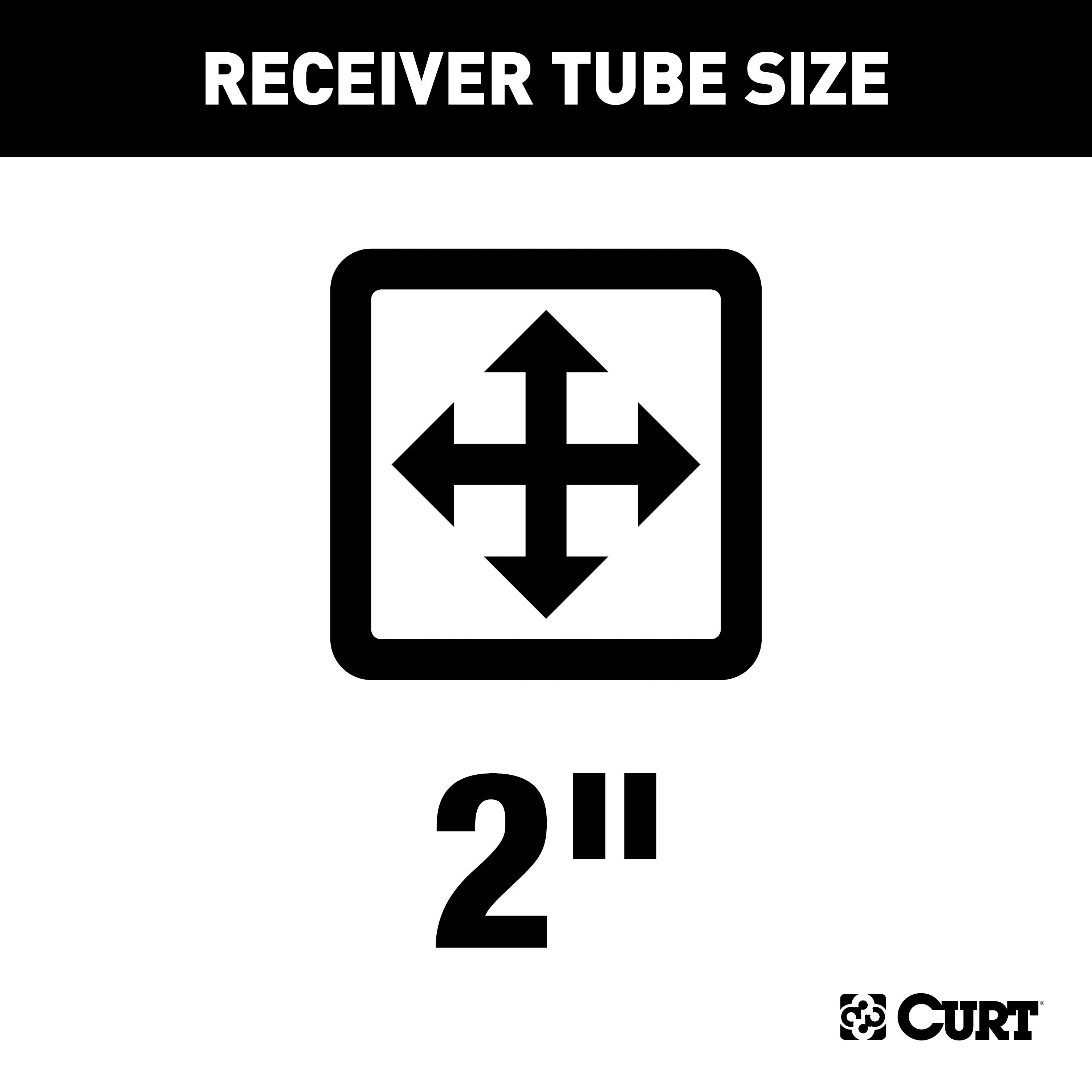
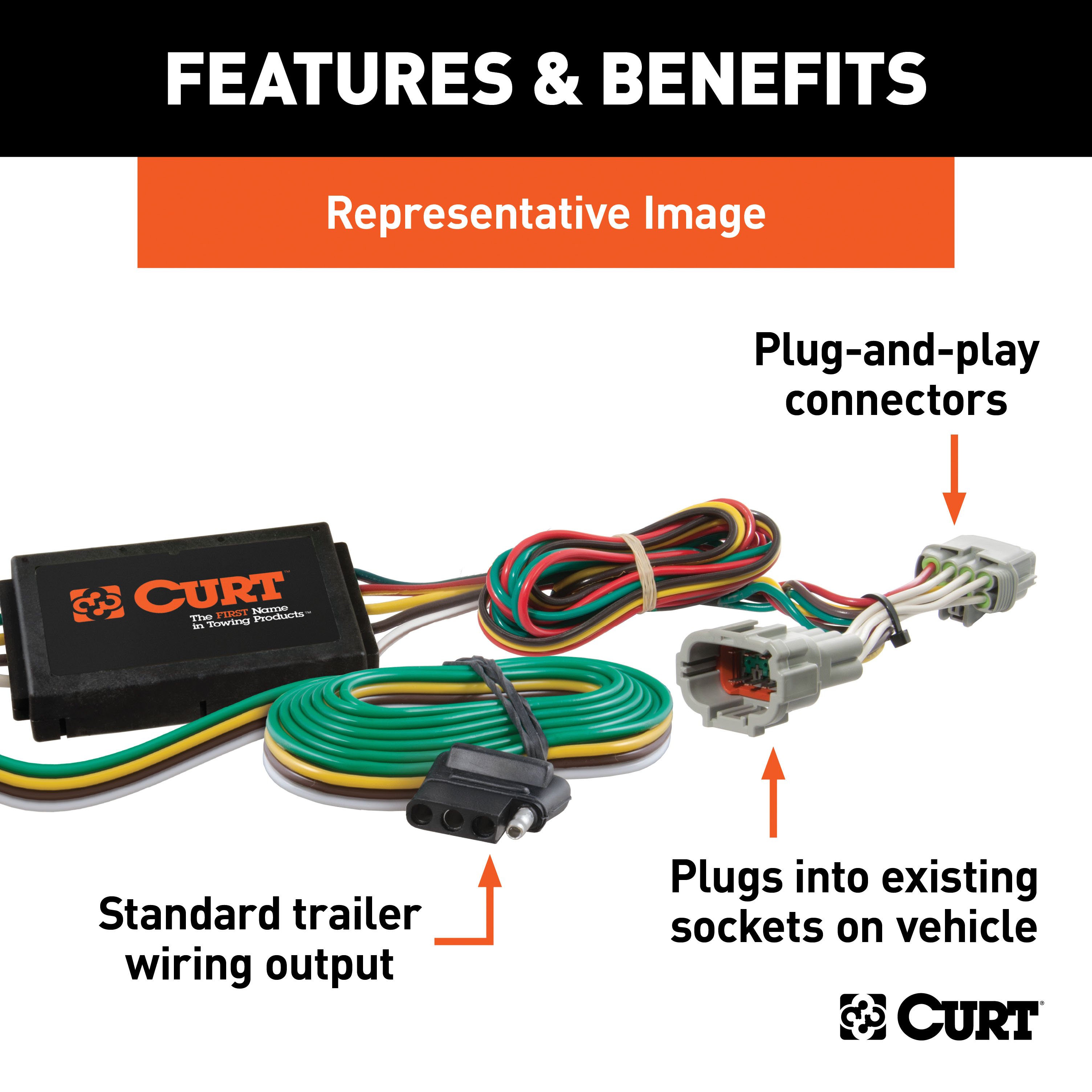
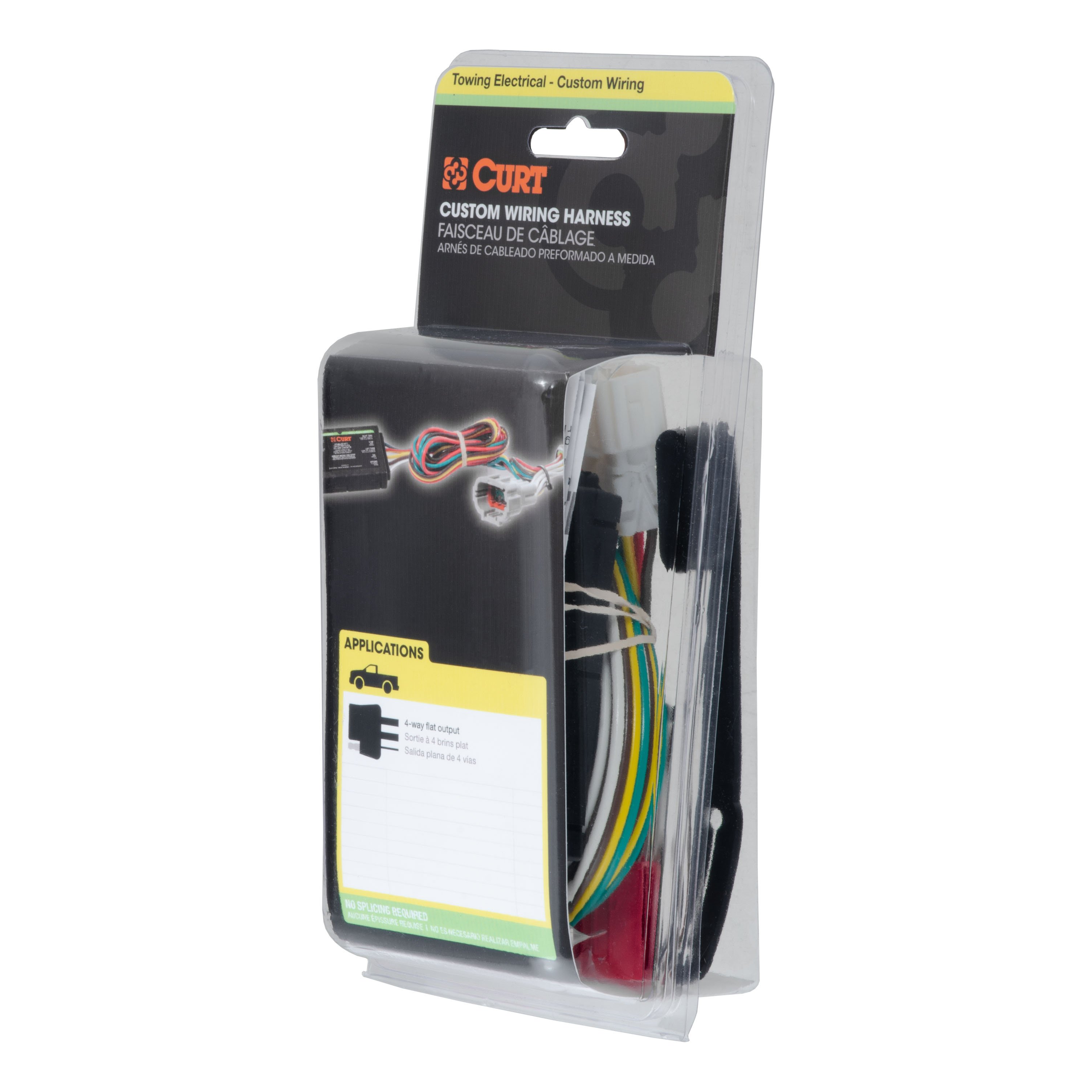
- Includes: Class 3 Trailer Tow Hitch, Custom Wiring Harness
Compatibility Chart
Get Expert Help
For 2021-2024 Volvo XC90 Trailer Hitch + Wiring 4 Pin Fits Recharge Curt 13233 56285 2 inch Tow Receiver Install Notes
Installation Instructions for Volvo XC90 SUV (2016-Present)
Part Numbers:
- 13233
Tools Required:
- Ratchet
- Torque Wrench
- T25 Torx Bit
- 10mm Socket
- 13mm Socket
- 8" Socket Extension
- Drill
- 1/2" Drill Bit
- Aviation Shears
- Safety Glasses
Step-by-Step Instructions:
Step 1: Remove Fasteners
- Use a T25 Torx bit to remove four fasteners attaching the bottom of the fascia to the vehicle.
Step 2: Lower the Exhaust
- Use a 13mm socket to remove two M10 bolts securing the exhaust brackets.
- Lower the exhaust to create space for installation.
Step 3: Remove and Trim the Heat Shield
- Use a 10mm socket to remove two M6 bolts holding the heat shield.
- Remove four speed clips from the heat shield studs and remove the heat shield.
- Trim the heat shield as per the provided trim diagram using shears or a rotary tool.
Step 4: Remove Additional Fasteners
- Remove four fasteners from each side of the wheel well using a T25 Torx bit.
Step 5: Remove the Bumper Fascia
- Carefully remove the bumper fascia, starting from the sides and working towards the center.
- Detach any connected sensors and mark them for proper reinstallation.
Step 6: Prepare the Frame
- Align the hitch using the exhaust bracket attachment points.
- Using the hitch as a template, mark the hole locations on the vehicle frame.
- Enlarge the forward-most hole on each frame rail to approximately 1" using a die grinder.
- Drill the rear-most holes on each frame rail using a 9/16" drill bit.
Step 7: Fishwire the Bolts
- Fishwire one 1/2" carriage bolt and spacer from the forward-most hole to the rear-most hole on each frame rail.
- Reverse fishwire one 1/2" carriage bolt and spacer into the forward-most hole on each frame rail.
Step 8: Install the Hitch
- Raise the hitch into position and pull the fishwires to align the bolts with the holes.
- Carefully remove the fishwires and loosely install the supplied 1/2" hex flange nuts.
Step 9: Reinstall the Exhaust
- Raise the exhaust into place and loosely secure it using the factory M10 bolts.
Step 10: Torque the Hardware
- Torque all 1/2" bolts to 110 ft-lbs.
- Torque all M10 bolts to 48 ft-lbs.
Step 11: Reassemble
- Reinstall the bumper fascia, sensors, and other components removed in Steps 1-5 in reverse order.
Heat Shield Trim Diagram:
- Follow the provided diagram for trimming the heat shield. Trim dimensions are approximately 2.75" x 8.00".
Hardware List:
- (4) 1/2"-13 UNC Carriage Bolts, 1-1/2"
- (4) .250 x 1.00 x 2.50" Square Hole Spacers
- (4) 1/2"-13 UNC Hex Flange Nuts
- (4) 1/2" Fishwire
Safety Notes:
- Wear safety glasses during installation.
- Periodically inspect the hitch to ensure all fasteners are tight and structural components are sound.
Warnings:
- Do not exceed the vehicle manufacturer's recommended towing capacity.
- Use stabilizing straps for all non-trailer loads to avoid damage and maintain safety.
Specifications:
- Gross Trailer Weight: 6,000 lbs
- Tongue Weight: 900 lbs
- Complies with SAE J684 and V.E.S.C. Regulation V-5
General Notes:
Attention: This is a summary of the installation procedure. For complete installation instructions, including diagrams and detailed information, please download the full installation PDF.
Warranty Information:
For warranty coverage details, including duration and terms, please download the full installation PDF. For technical support and assistance, our team of experts is available to help. You can reach our tech support by visiting www.trailerjacks.com or calling 877-869-6690.
Installation Instructions for Volvo S90 and XC90
Part Number:
- 56285
Wiring Access Locations:
- S3: Behind driver side rear access panel
- S4: Behind passenger side rear access panel
Tools Required:
- Ratchet
- 10mm socket
- 8mm socket
- Panel trim removal tool
- Cutting tool
Step-by-Step Instructions:
-
Prepare Trunk Area:
- Open the vehicle trunk.
- Remove all trunk floor coverings.
-
Disconnect Battery:
- Locate the vehicle battery by removing the access panel on the driver side.
- Disconnect the negative battery terminal.
-
Remove Rear Scuff Panel:
- Remove the fasteners securing the rear scuff panel.
- Pull out on the bottom of the scuff panel and then lift up to remove it.
- Take care not to damage the alignment tabs on the back.
-
Access Driver Side Taillight Wiring:
- Behind the driver side trim panel, locate the vehicle's taillight wiring harness connectors.
- The connectors will be similar to those on the custom wiring harness.
- Separate the connectors from the taillight housing, taking care not to damage the locking tabs.
-
Install Custom Wiring Harness (Driver Side):
- Insert the custom wiring harness end with the yellow wire between the separated connectors.
- Ensure the connectors are fully inserted with locking tabs in place.
-
Ground the White Wire:
- Locate a suitable grounding point near the connector, such as an existing screw with a nut in the vehicle frame, or drill a 3/32" pilot hole for the provided screw.
- Ensure the area is free of rust, dirt, and paint.
- Secure the white ground wire using the ring terminal and provided screw.
- Warning: Check for miscellaneous items that may be hidden behind or under any surface before drilling to avoid damage and/or personal injury.
-
Route Wiring Harness to Passenger Side:
- Route the custom wiring harness end with the green wire to the passenger side behind the removed scuff panels.
-
Access Passenger Side Taillight Wiring:
- Remove the storage tray from the passenger side.
- Remove the fasteners securing the cargo tie-down.
- Pull back on the side trim panel to access the taillight wiring harness connectors.
- Repeat steps 4 and 5 on the passenger side using the custom wiring harness end with the green wire.
-
Mount Converter Box:
- Locate a flat spot inside the vehicle, near the taillight.
- Adhere the black converter box using the provided double-sided tape.
-
Connect Power Wire:
- Route the power wire to the battery's positive (+) terminal.
- Using a 10mm socket, remove the nut on the positive (+) terminal auxiliary stud.
- Attach the power wire's ring terminal and reinstall the nut.
-
Position 4-Flat Connector:
- When in use, route the 4-flat to the center of the vehicle.
- When not in use, roll up and store in a convenient, out-of-the-way location.
- Secure any loose wires with the provided cable ties.
-
Reassemble Vehicle Components:
- Reinstall all items removed during installation.
- Reconnect the negative battery terminal.
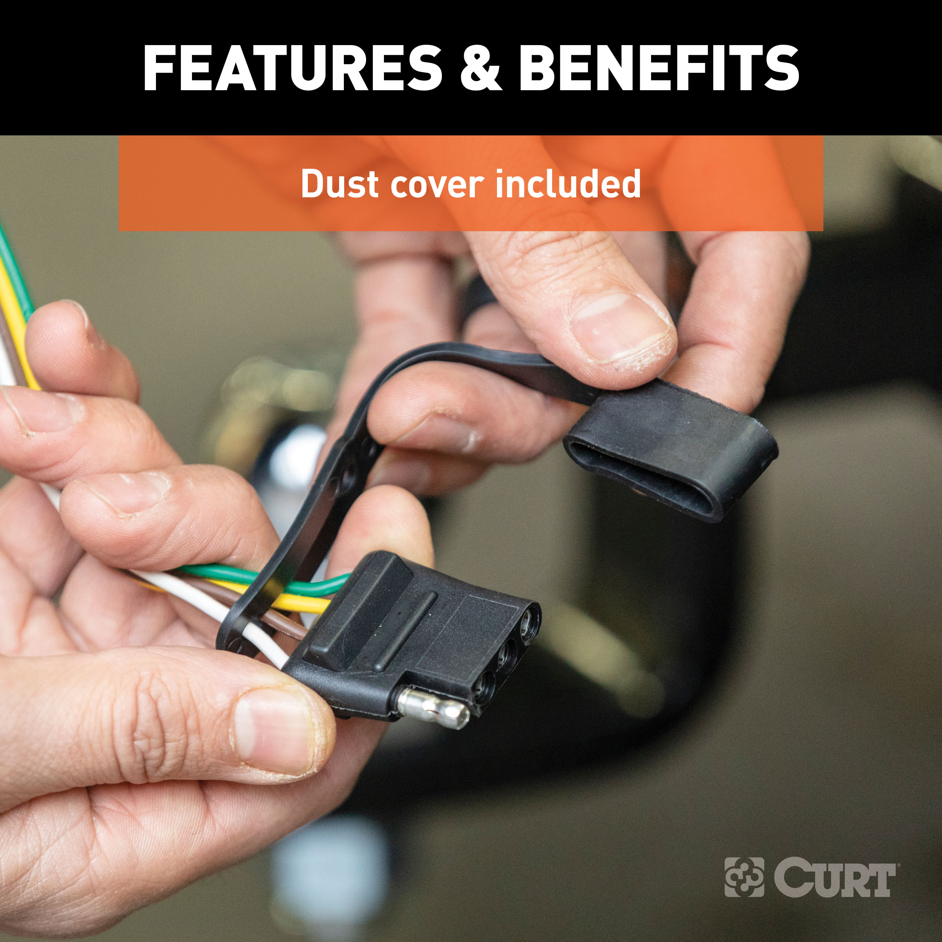
- Install the provided 4-flat dust cover to help prevent corrosion.
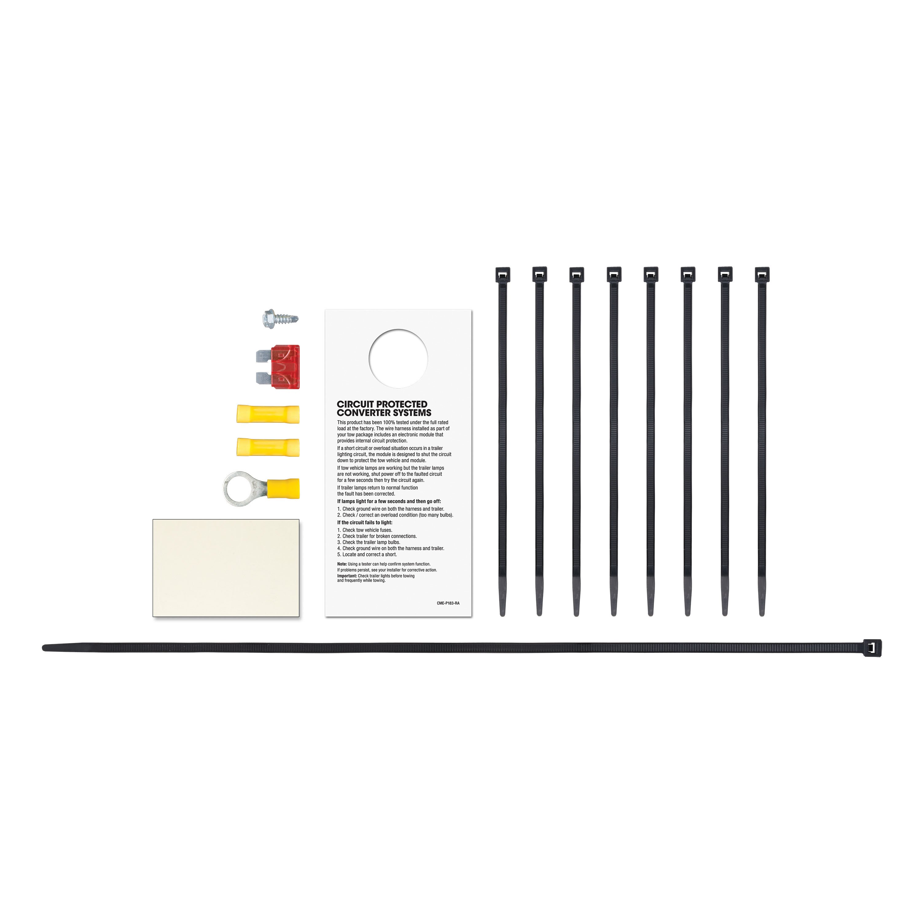
Hardware List:
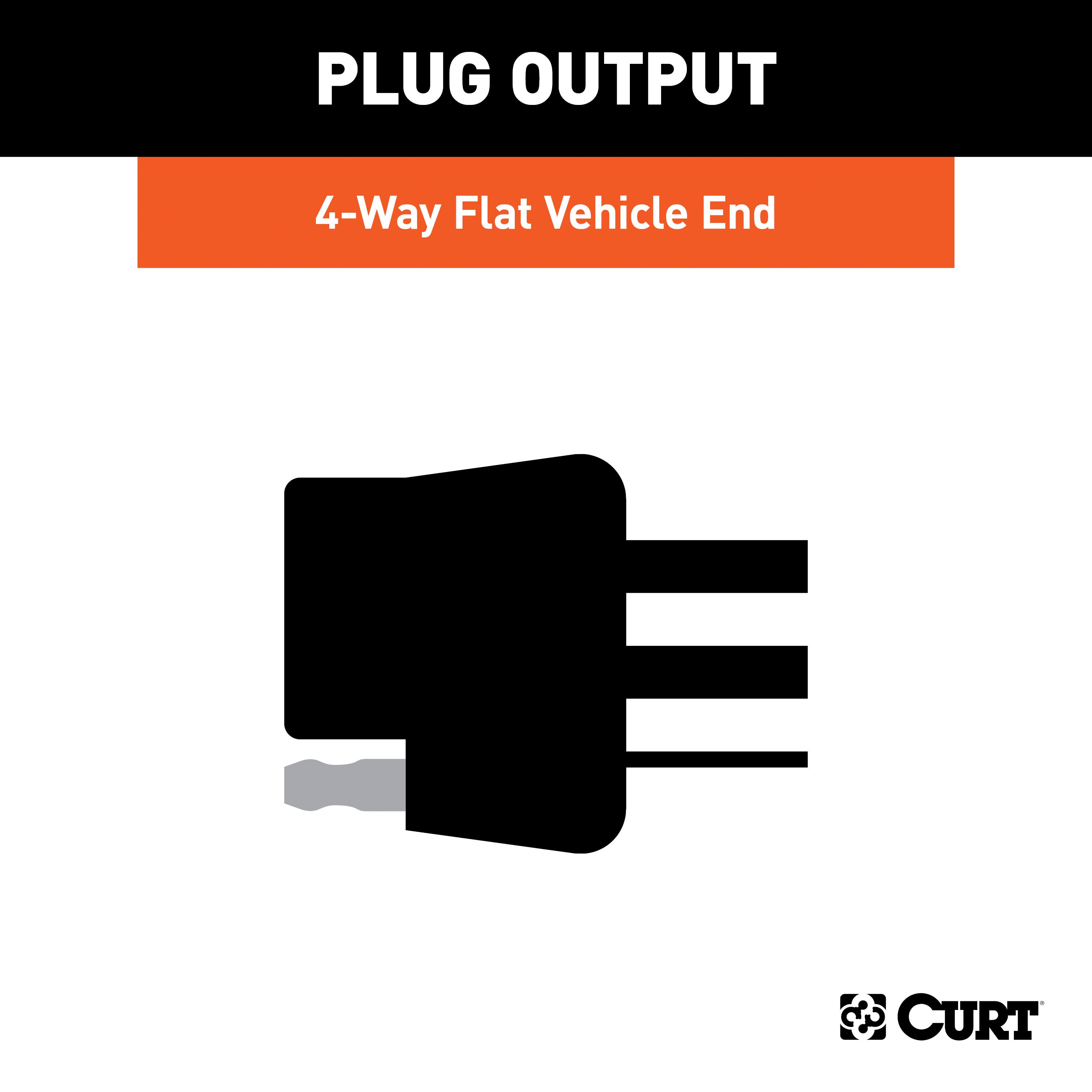
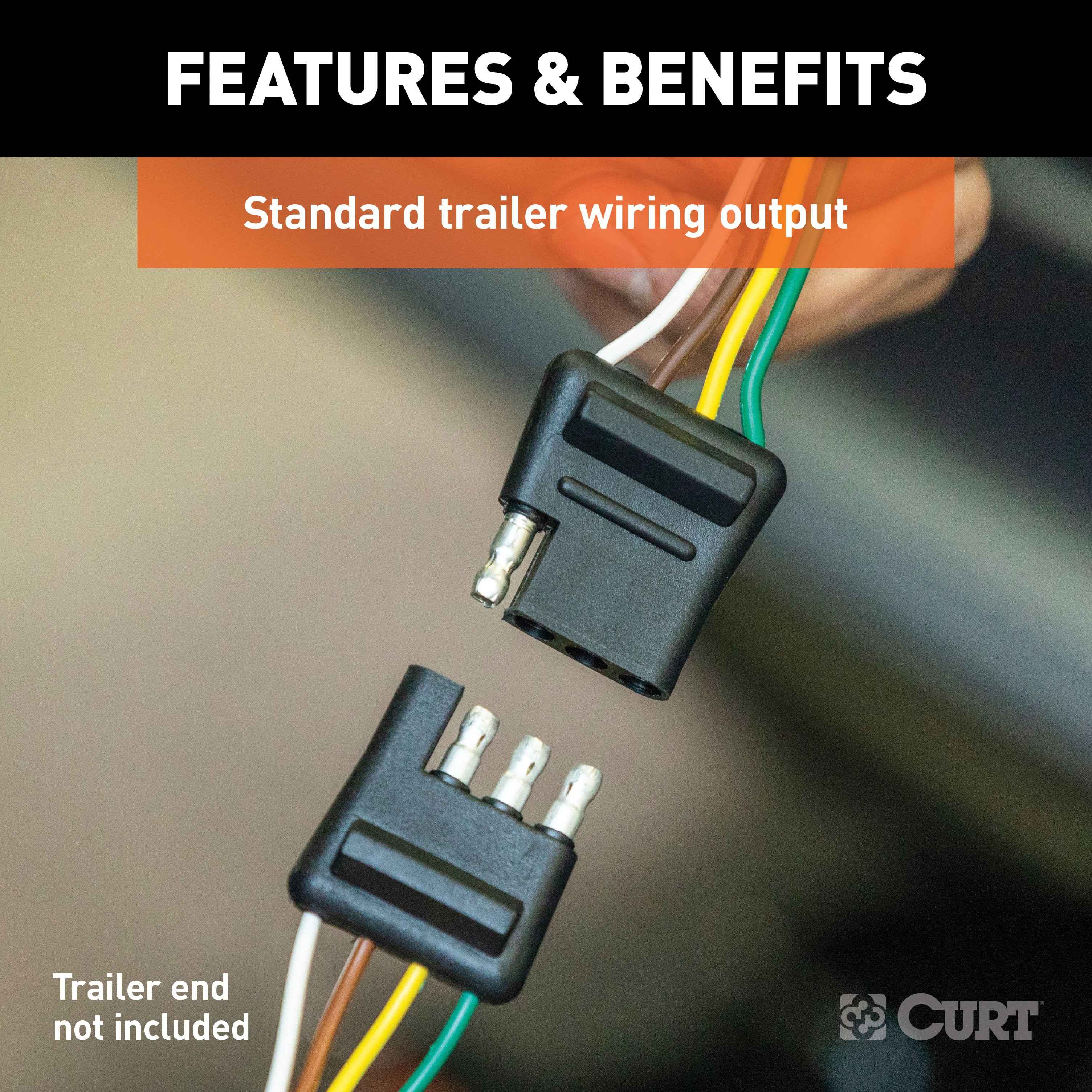
- Custom wiring harness with 4-flat connector
- Black converter module
- Double-sided tape
- Ring terminal
- Ground screw
- Cable ties
- 10-amp fuse (for fuse holder on converter harness)
- 4-flat dust cover
Safety Notes:
- Battery Connection: The battery connection must be fuse-protected with a 10-amp max fuse. Exceeding the product rating can cause loss of warranty, overheating, and potential fire. Do not exceed the product rating or the tow vehicle lamp load rating, whichever is lower.
- Drilling Caution: Check for miscellaneous items that may be hidden behind or under any surface before drilling to avoid damage and/or personal injury.
Specifications:
- Signal Circuits: 3.0 amps per side
- Tail/Running Circuits: 6.0 amps total
(Refer to the vehicle owner's manual or contact the vehicle manufacturer for more information.)
Installation Instructions
Part Number:
- 56285
Wiring Access Locations:
- S3: Behind driver side rear access panel
- S4: Behind passenger side rear access panel
Tools Required:
- Ratchet
- 10mm socket
- 8mm socket
- Panel trim removal tool
- Cutting tool
Step-by-Step Instructions:
-
Prepare Trunk Area:
- Open the vehicle trunk.
- Remove all trunk floor coverings.
-
Disconnect Battery:
- Locate the vehicle battery by removing the access panel on the driver side.
- Disconnect the negative battery terminal.
-
Remove Rear Scuff Panel:
- Remove the fasteners securing the rear scuff panel.
- Pull out on the bottom of the scuff panel and then lift up to remove it.
- Take care not to damage the alignment tabs on the back.
-
Access Driver Side Taillight Wiring:
- Behind the driver side trim panel, locate the vehicle's taillight wiring harness connectors.
- The connectors will be similar to those on the custom wiring harness.
- Separate the connectors from the taillight housing, taking care not to damage the locking tabs.
-
Install Custom Wiring Harness (Driver Side):
- Insert the custom wiring harness end with the yellow wire between the separated connectors.
- Ensure the connectors are fully inserted with locking tabs in place.
-
Ground the White Wire:
- Locate a suitable grounding point near the connector, such as an existing screw with a nut in the vehicle frame, or drill a 3/32" pilot hole for the provided screw.
- Ensure the area is free of rust, dirt, and paint.
- Secure the white ground wire using the ring terminal and provided screw.
- Warning: Check for miscellaneous items that may be hidden behind or under any surface before drilling to avoid damage and/or personal injury.
-
Route Wiring Harness to Passenger Side:
- Route the custom wiring harness end with the green wire to the passenger side behind the removed scuff panels.
-
Access Passenger Side Taillight Wiring:
- Remove the storage tray from the passenger side.
- Remove the fasteners securing the cargo tie-down.
- Pull back on the side trim panel to access the taillight wiring harness connectors.
- Repeat steps 4 and 5 on the passenger side using the custom wiring harness end with the green wire.
-
Mount Converter Box:
- Locate a flat spot inside the vehicle, near the taillight.
- Adhere the black converter box using the provided double-sided tape.
-
Connect Power Wire:
- Route the power wire to the battery's positive (+) terminal.
- Using a 10mm socket, remove the nut on the positive (+) terminal auxiliary stud.
- Attach the power wire's ring terminal and reinstall the nut.
-
Position 4-Flat Connector:
- When in use, route the 4-flat to the center of the vehicle.
- When not in use, roll up and store in a convenient, out-of-the-way location.
- Secure any loose wires with the provided cable ties.
-
Reassemble Vehicle Components:
- Reinstall all items removed during installation.
- Reconnect the negative battery terminal.
- Install the provided 4-flat dust cover to help prevent corrosion.
Hardware List:
- Custom wiring harness with 4-flat connector
- Black converter module
- Double-sided tape
- Ring terminal
- Ground screw
- Cable ties
- 10-amp fuse (for fuse holder on converter harness)
- 4-flat dust cover
Safety Notes:
- Battery Connection: The battery connection must be fuse-protected with a 10-amp max fuse. Exceeding the product rating can cause loss of warranty, overheating, and potential fire. Do not exceed the product rating or the tow vehicle lamp load rating, whichever is lower.
- Drilling Caution: Check for miscellaneous items that may be hidden behind or under any surface before drilling to avoid damage and/or personal injury.
Specifications:
- Signal Circuits: 3.0 amps per side
- Tail/Running Circuits: 6.0 amps total
Attention:
This is a summary of the installation procedure. For complete installation instructions, including diagrams and detailed information from the manufacturer, please download the full installation PDF.
Technical Support:
For technical support and assistance, our team of experts is available to help. You can reach our tech support by visiting www.trailerjacks.com or calling 877-869-6690.
Warranty Information:
For complete warranty instructions, please download the full installation PDF.
(Refer to the vehicle owner's manual or contact the vehicle manufacturer for more information.)


