




For 2022-2024 Ford F150 Trailer Hitch + Wiring 4 Pin Fits Models w/ Factory Receiver w/ USCAR 7-way Factory Connector Curt 14021 55384 2 inch Tow Receiver
Model: 14021 55384-CH1370This Trailer Tow Hitch + 4-Flat Fits The Following Vehicles:
2022 - 2024 Ford F-150 w/ Factory Receiver with Existing USCAR 7-way Socket
This Trailer Tow Hitch + 4-Flat Includes the Following Parts:
- Class 4 Trailer Hitch, 2" Receiver (Easy Bolt-On, No Drilling)
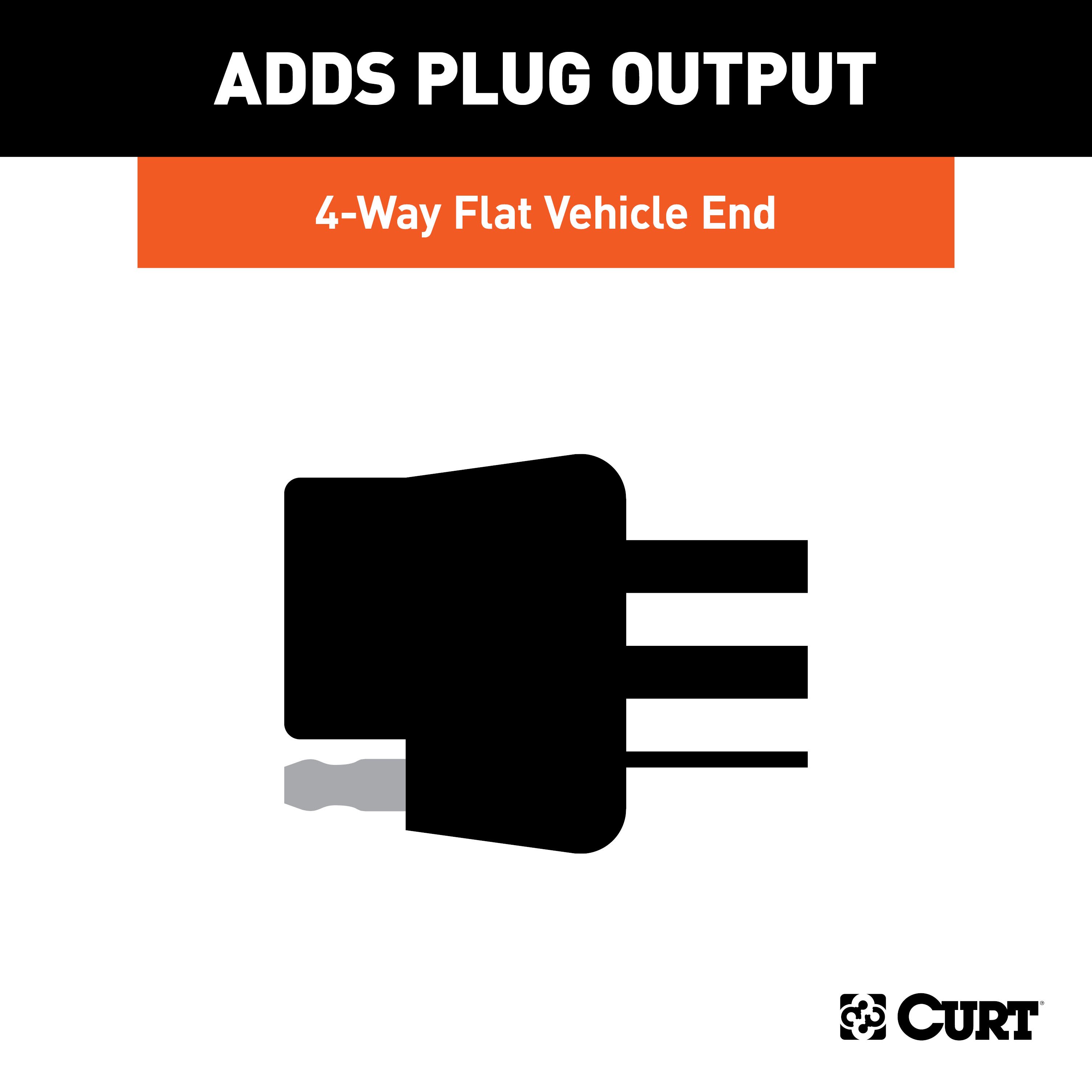
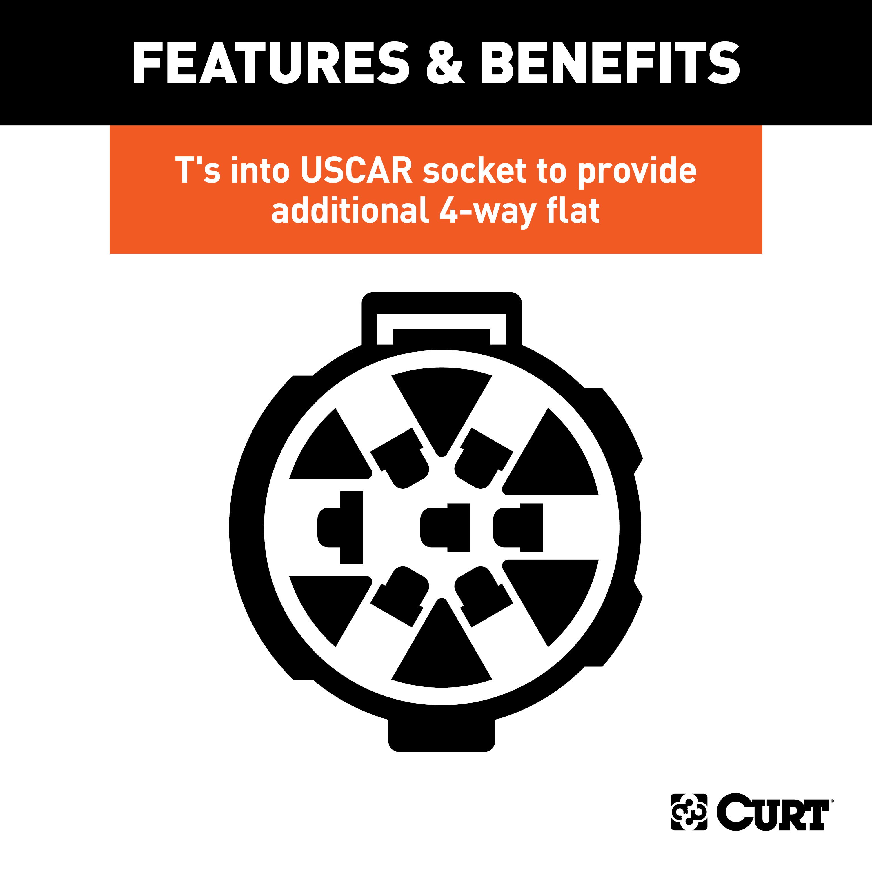
- Replacement OE 4-Way Flat Socket (T's into USCAR)
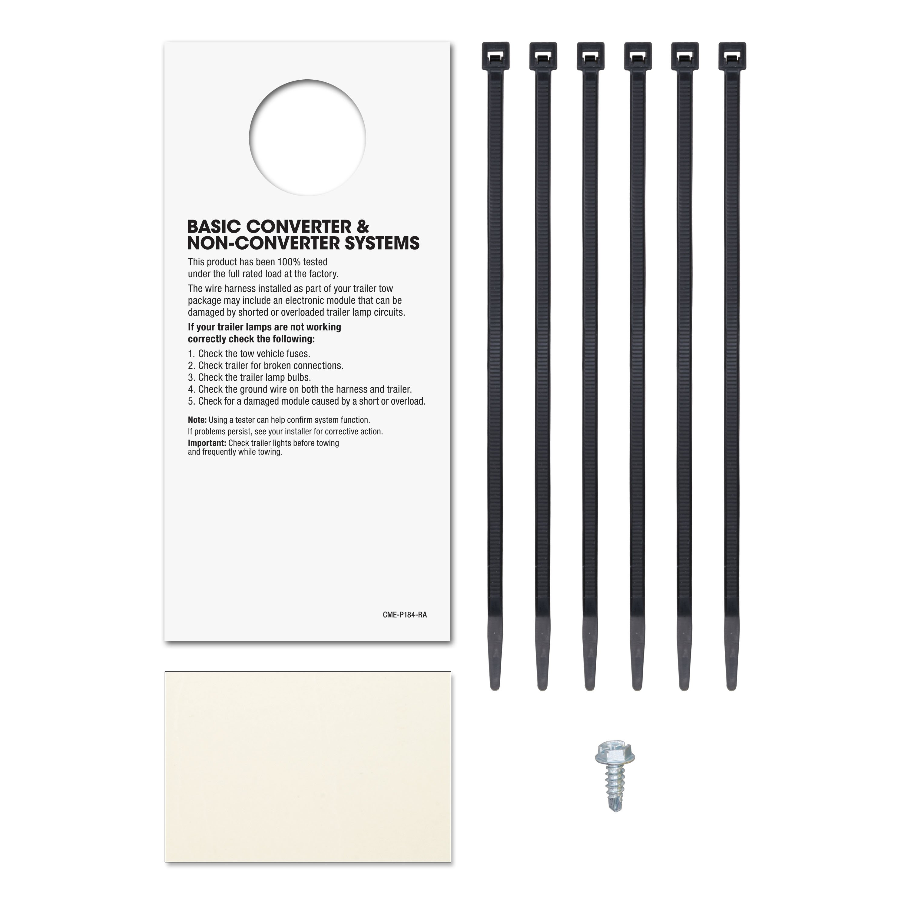
- Installation instructions, schematics, diagrams, and hardware (if required).
List of Fitment Years:
2022, 2023, 2024
CURT 14021 Class 4 Trailer Hitch, 2-Inch Receiver
Manufactured by: Curt
Whatever the next item is on your to-do list -- whether it's arriving at the jobsite before dawn or getting your travel trailer set up in time to see the sunset -- CURT class 4 trailer hitches offer greater towing power to let you Bring It These custom receiver hitches are built to tackle bigger jobs and bolder adventures, all while giving you a custom fit for your vehicle Class 4 hitches are available for a variety of makes and models, from pickup trucks and SUVs to full-size and commercial vans.
This particular class 4 hitch fits certain years of the Ford F-150 (to verify vehicle compatibility, see application info) It provides a weight carrying capacity of 10,000 lbs GTW and 1,000 lbs.
TW It can also accept a weight distributing hitch, offering a maximum WD capacity of 12,000 lbs and a WDTW of 1,200 lbs.
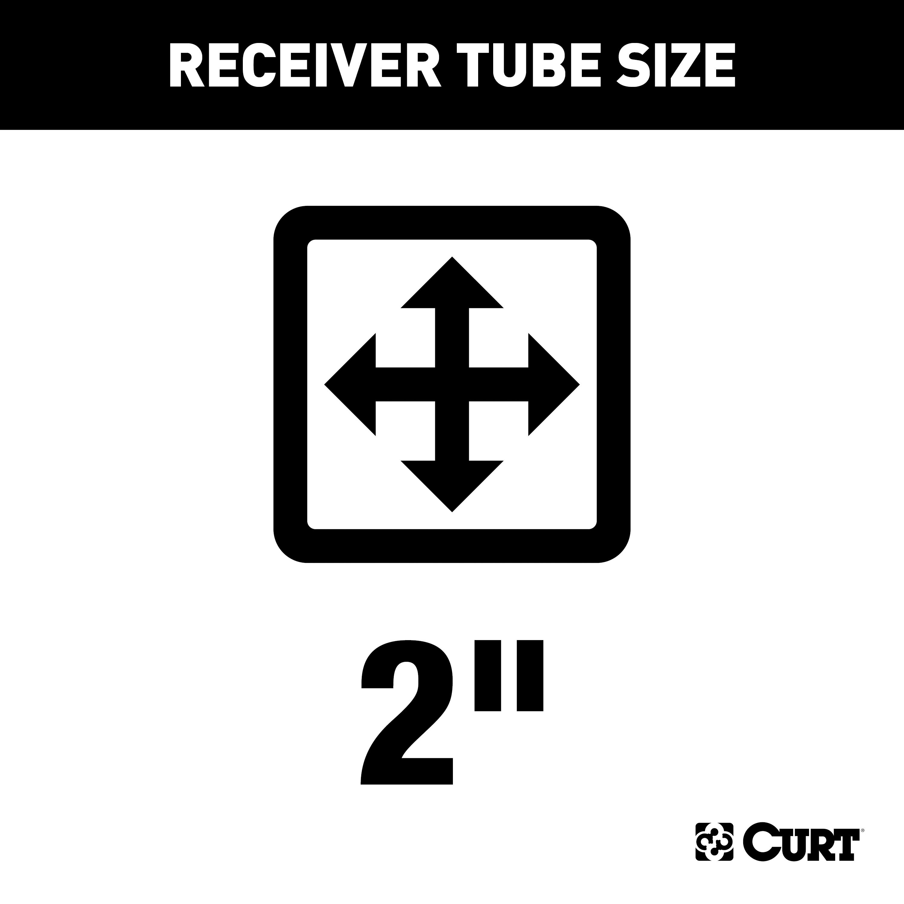
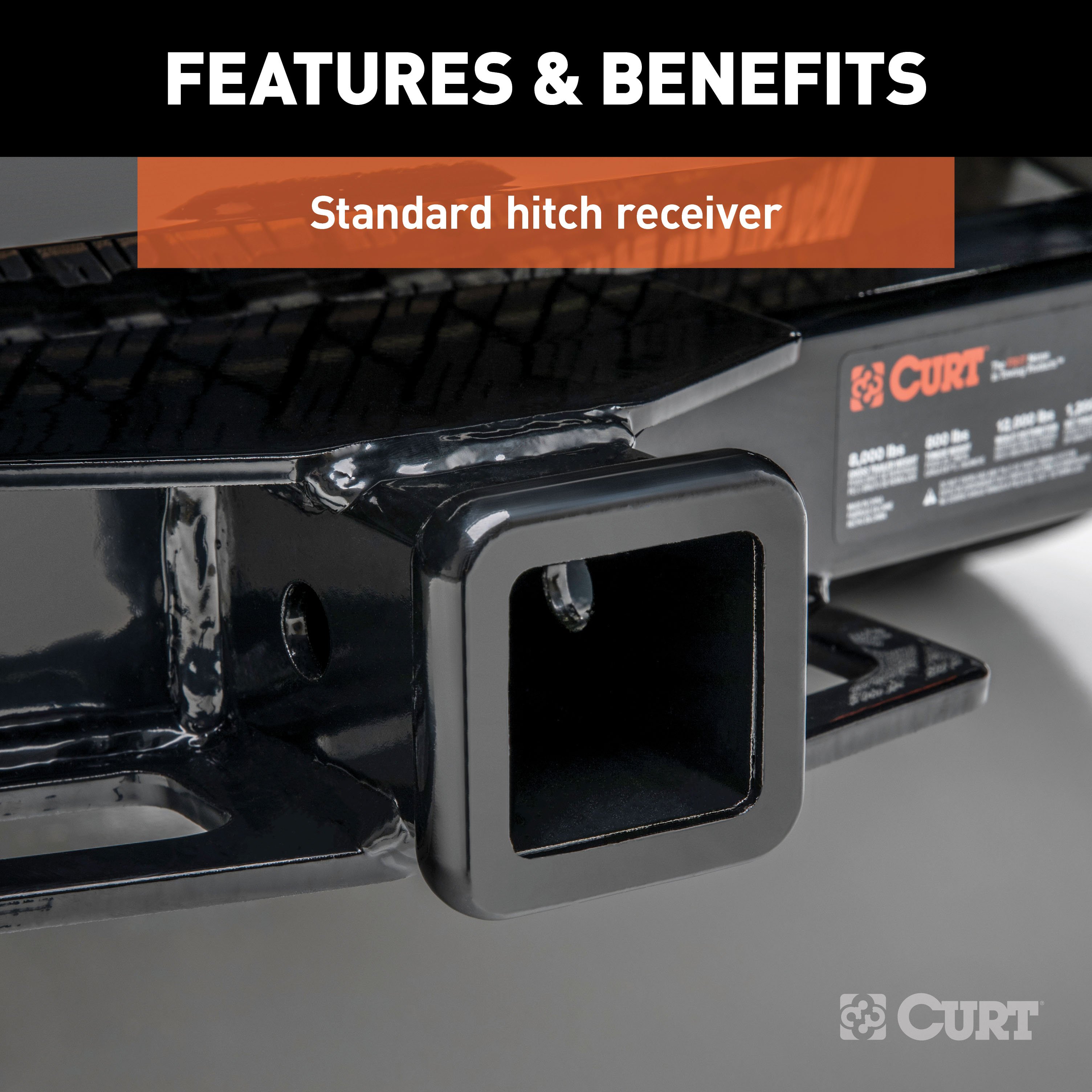
CURT class 4 tow hitches are as much suited for work as they are for play With their high load capacities, they are typically used for towing larger trailers, including everything from a double-axle utility trailer or livestock trailer to a full-length camper or large boat trailer (NOTE: Never exceed the lowest weight capacity of any towing component) All CURT class 4 receiver hitches come with a 2" receiver tube opening and all the necessary hardware for a complete installation.
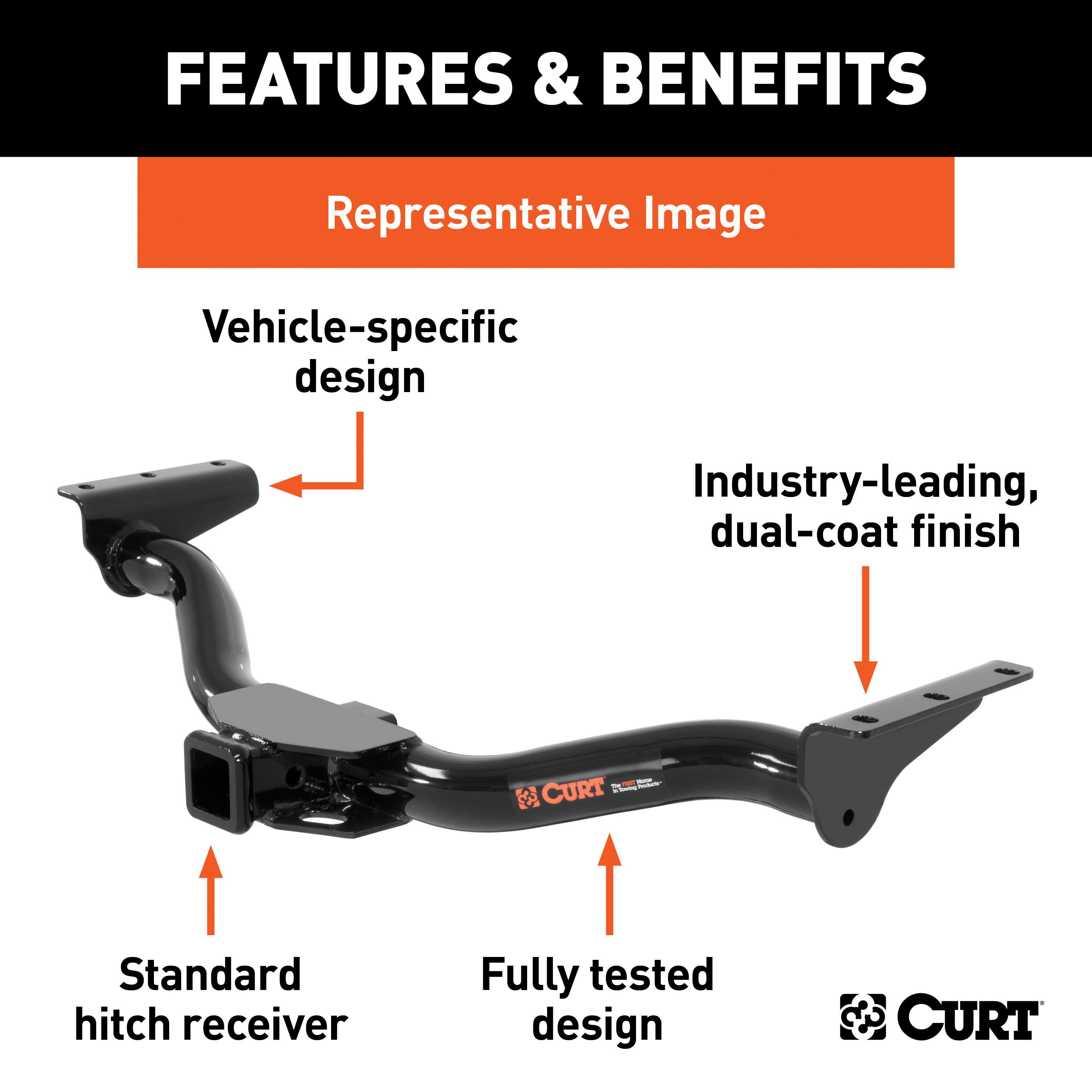
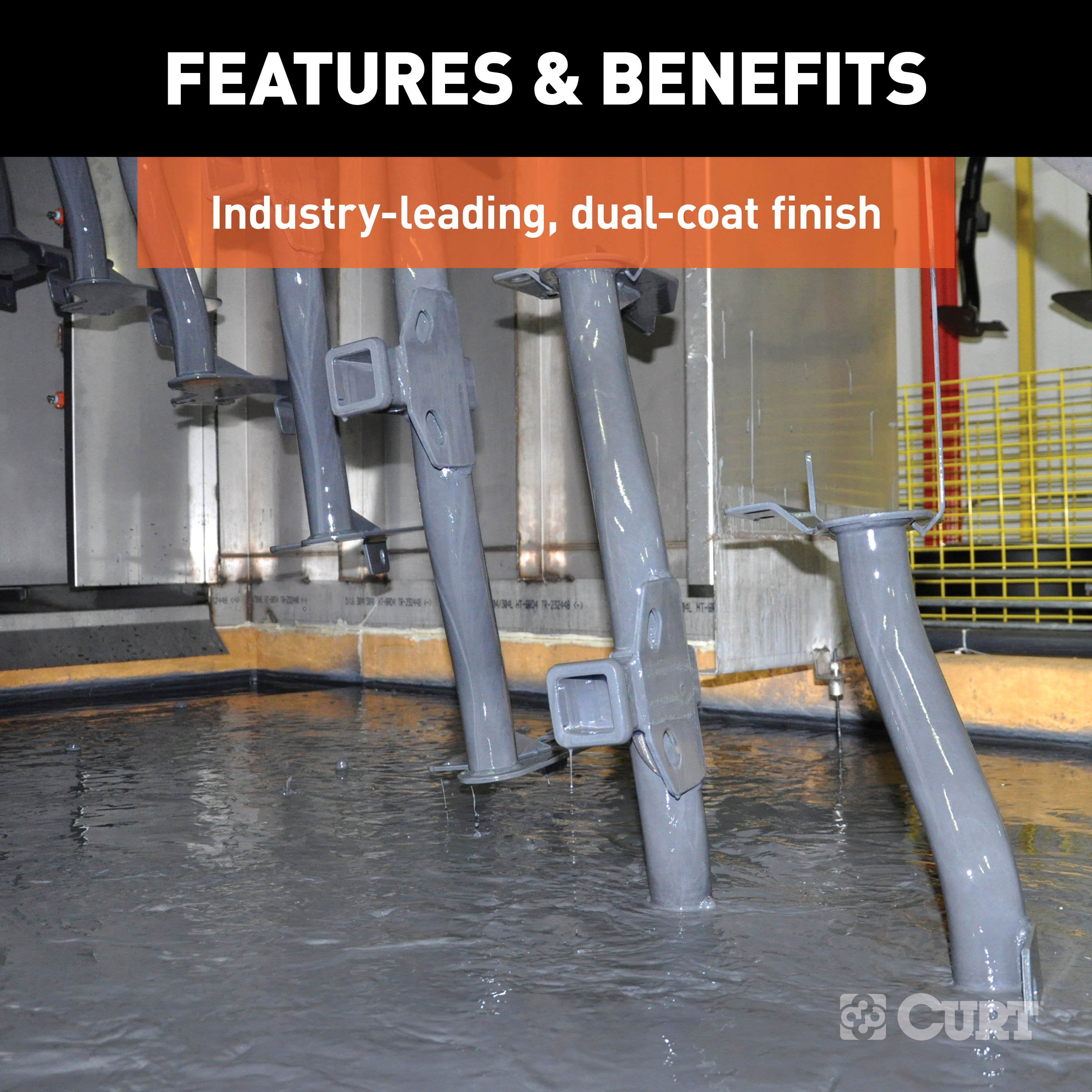
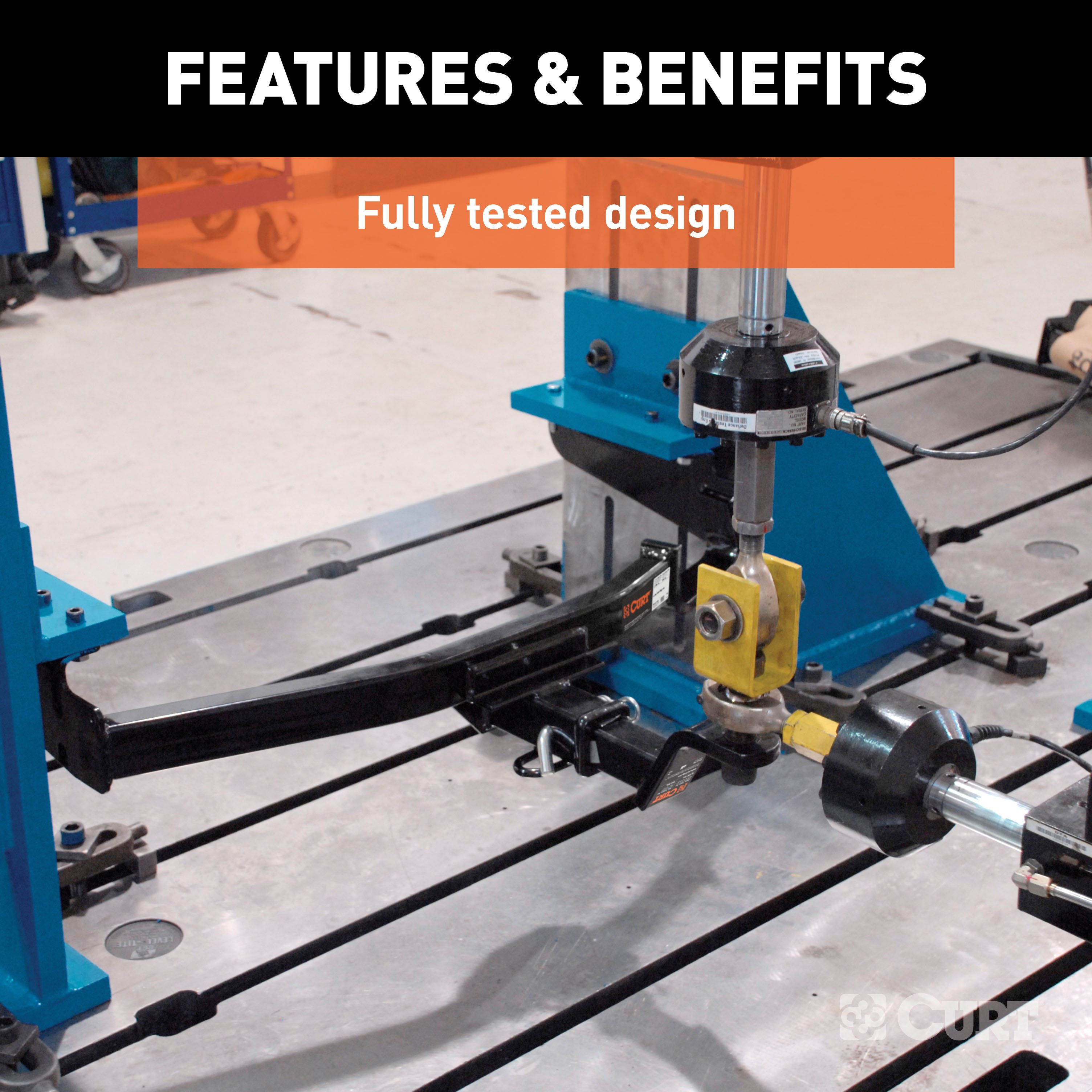
From light-duty to heavy-duty, every CURT custom hitch is engineered to be vehicle-specific, using actual vehicles to create the optimal design We then combine high-strength steel, precise welding and a co-cured finish of liquid A-coat and durable black powder coat to provide you with a hitch you can depend on To prove it, we test all our hitches in accordance with SAE J684 for safety..
Features:
- Rated to 10,000 lbs. gross trailer weight and 1,000 lbs. tongue weight
- Compatible with weight distribution hitch (12,000 lbs. WD / 1,200 lbs. WDTW)
- Engineered with a vehicle-specific design for a custom fit
- Tested for safety in accordance with SAE J684
- Precisely welded for superior strength and fit
- Protected by a durable high-gloss black powder coat finish
- Co-cured in a rust-resistant liquid A-coat, inside and out
- Equipped with an open-back receiver for easy cleaning
- Limited lifetime warranty (one-year finish, one-year parts)
- Made in USA (may include imported hardware)
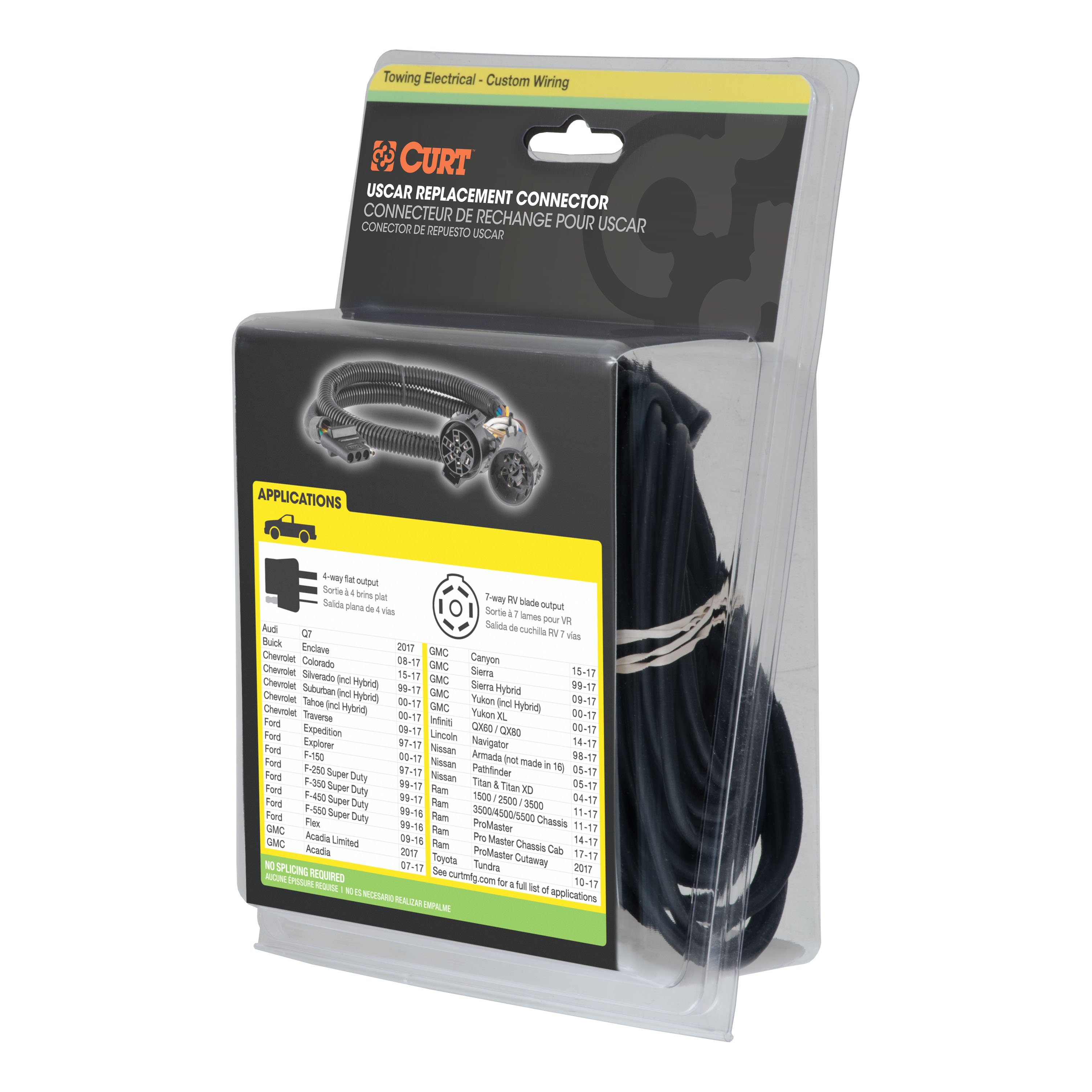
CURT 55384 Replacement Vehicle-Side Custom USCAR 4-Pin Trailer Wiring Harness
Manufactured by: Curt
Stress is the last thing you should feel when towing a trailer -- whether you're hauling your RV to that favorite camping destination, your ATVs up to the hunting grounds or your fishing boat to the new hidden hotspot At CURT, we think your towing equipment should add to the enjoyment of your experience, not detract from it CURT custom wiring connectors are the easiest way to outfit your vehicle with a CURT trailer wiring connection.
They are built with some of the most advanced technology in the industry, and each one is custom-fitted to work with a specific make and model Some automotive manufacturers install a special socket on the vehicle to be used for vehicle-to-trailer wiring Though this special socket is not equipped on every vehicle, a CURT custom wiring connector (also called a T-connector) utilizes the socket for simple, stress-free installation.
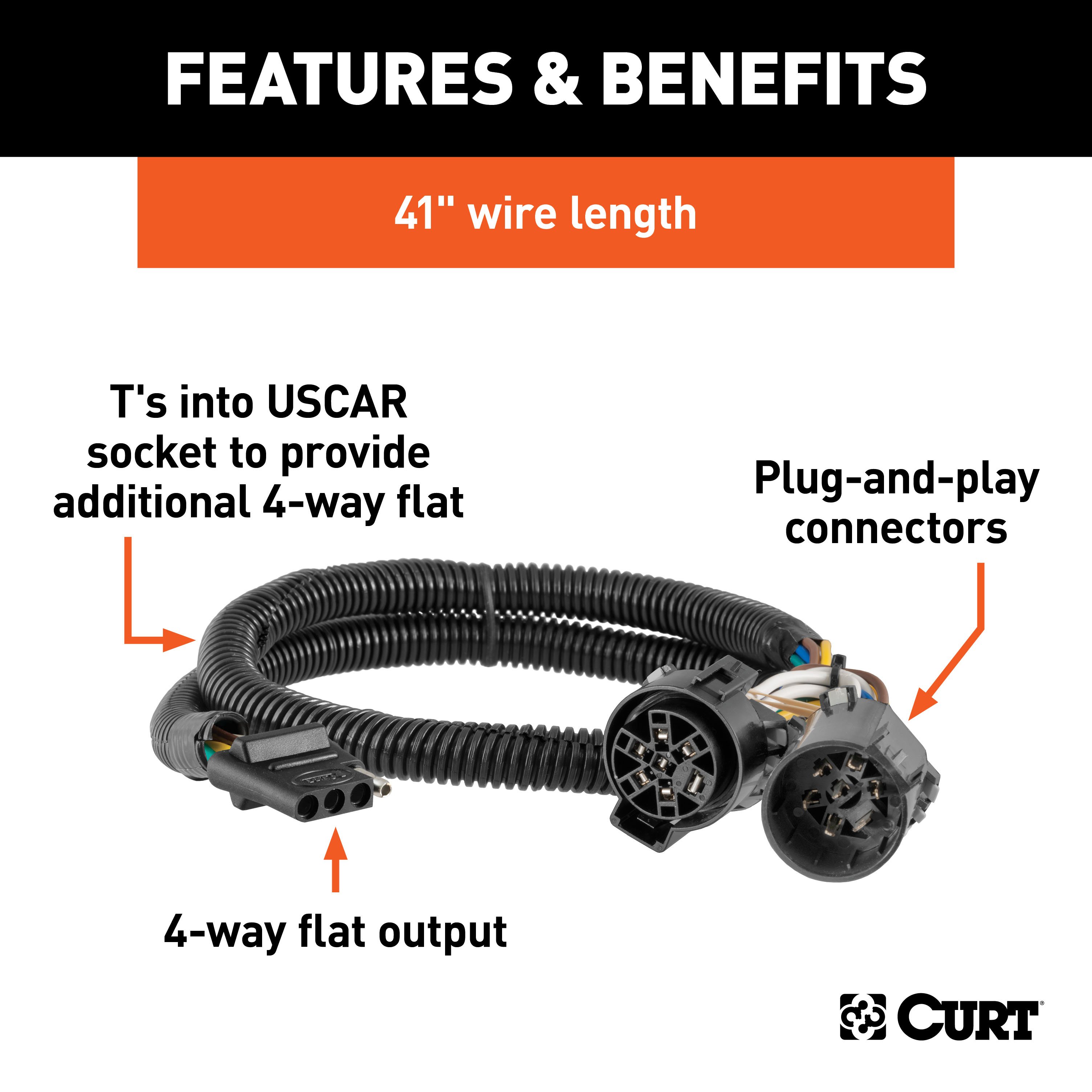
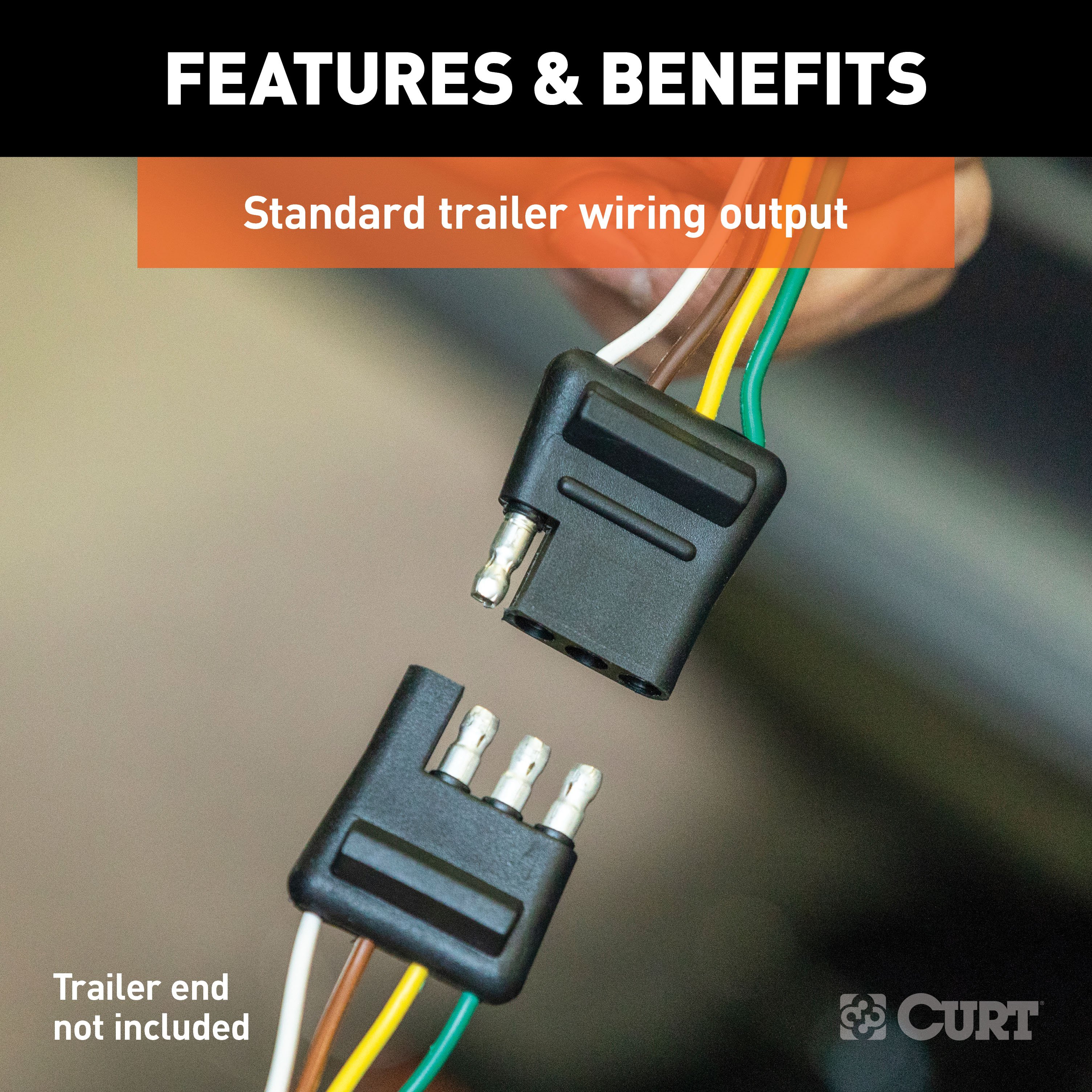
Rather than requiring you to cut, splice and solder into your vehicle's wiring system, the custom wiring connector uses a single OEM-compatible plug and instantly provides a standard vehicle-to-trailer wiring connection, typically in the form a 4-way flat All CURT custom wiring connectors are made vehicle-specific for the easiest possible installation and the best fit This particular connector provides a 4-way flat socket while retaining use of the existing OEM socket.
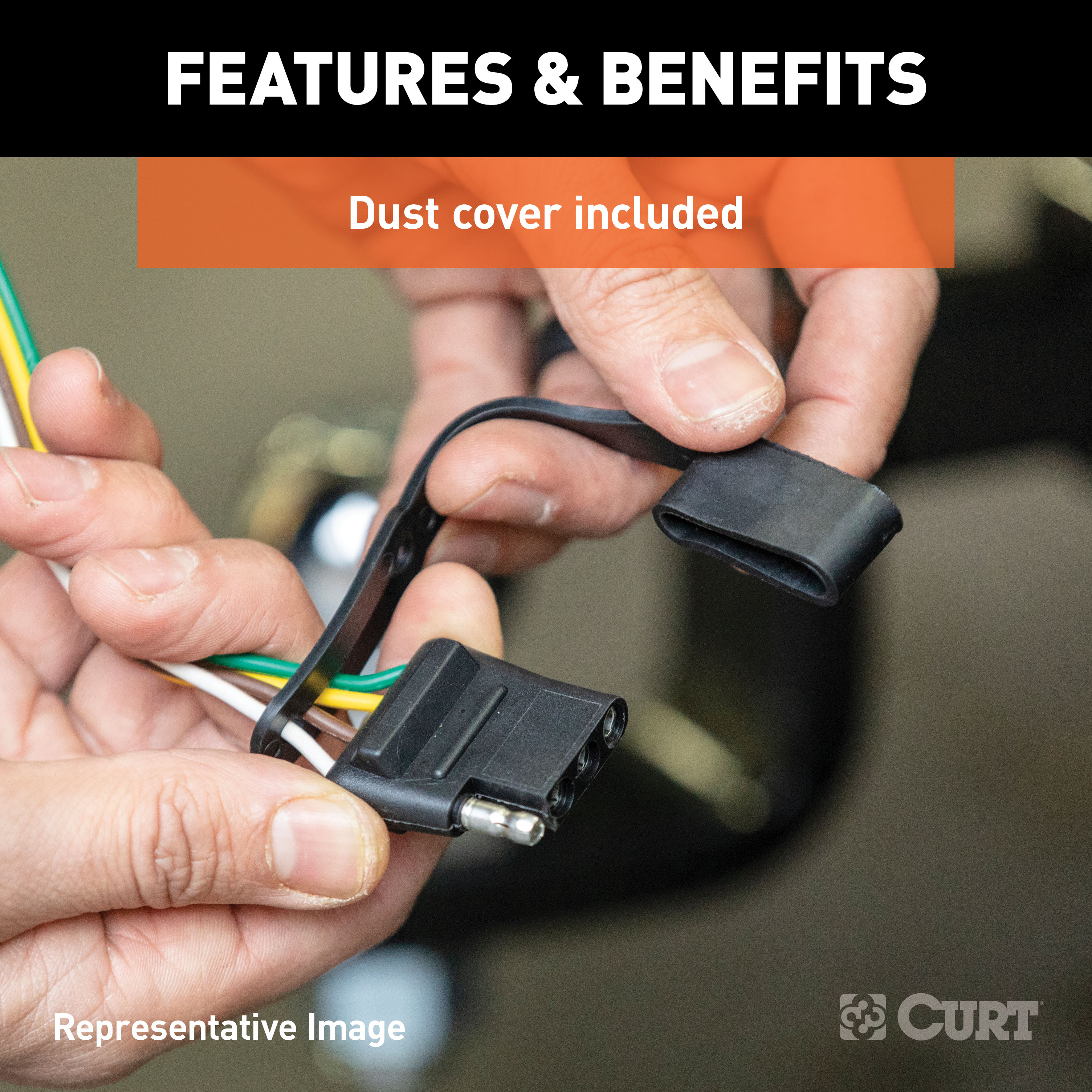
It is designed to be a custom wiring option for a variety of vehicles (see application info to verify fitment with your vehicle) It comes with a dust cover to keep the connector socket clean when not in use..
Features:
- Replacement OE 4-Way Flat Socket (T's into USCAR)
- Plugs into USCAR connection to add 4-way flat and retain use of existing socket
- Simple plug-and-play design eliminates the need for cutting or splicing
- 4-way flat output connects tail lights, brake lights and turn signals
- Dust cover included to keep connector clean when not in use
- Slit loom keeps wires contained and well protected
- Backed by a limited one-year warranty
Hitches Near Me: We operate out of several warehouses across the country, ensuring faster delivery to your location.
$309 99 $470.90 34% OFF
- Best Price on Web Guarantee
- Fastest Shipping
- FREE Shipping
- In Stock

We match lower prices from major authorized retailers for brand-new products in original packaging, provided the item is in stock. The competing seller must be an authorized, professional retail business; offers from
individuals, auctions, peer-to-peer sites, or unauthorized sellers don’t qualify. Used, refurbished, or open-box items are excluded.
Please see our full terms for details.
Verify Fitment
View products that fit your vehicle
Fits 's with the following styles:
View products that fit your vehicle
Fits 's with the following styles:
$470.90 $309 99
 Learn more
Questions? Call our Auto Experts at (877) 869-6690
Get it now, pay later
Select installments at checkout to split your purchase into 4 interest-free payments of $ every 2 weeks.
- No fees, ever.
- No impact on your credit score.
Payment options are offered by Affirm and are subject to an eligibility check and might not be available in all states. CA Residents: Loans by Affirm Loan Services, LLC are made or arranged pursuant to a California Finance Lender license.
Installments in partnership with


Each may be shipped from a separate location, and therefore, may arrive at different times
Product Details
- Brand: Curt
- Model: 14021 55384-CH1370
- Includes: Class 4 Trailer Tow Hitch, Replacement OE 4-Way Flat Socket T's into USCAR)
Compatibility Chart
| Year Range | Make | Model | Style |
|---|
This Trailer Tow Hitch + 4-Flat Fits The Following Vehicles:
2022 - 2024 Ford F-150 w/ Factory Receiver with Existing USCAR 7-way Socket
This Trailer Tow Hitch + 4-Flat Includes the Following Parts:
- Class 4 Trailer Hitch, 2" Receiver (Easy Bolt-On, No Drilling)
- Replacement OE 4-Way Flat Socket (T's into USCAR)
- Installation instructions, schematics, diagrams, and hardware (if required).
List of Fitment Years:
2022, 2023, 2024
CURT 14021 Class 4 Trailer Hitch, 2-Inch Receiver
Manufactured by: Curt
Whatever the next item is on your to-do list -- whether it's arriving at the jobsite before dawn or getting your travel trailer set up in time to see the sunset -- CURT class 4 trailer hitches offer greater towing power to let you Bring It These custom receiver hitches are built to tackle bigger jobs and bolder adventures, all while giving you a custom fit for your vehicle Class 4 hitches are available for a variety of makes and models, from pickup trucks and SUVs to full-size and commercial vans.
This particular class 4 hitch fits certain years of the Ford F-150 (to verify vehicle compatibility, see application info) It provides a weight carrying capacity of 10,000 lbs GTW and 1,000 lbs.
TW It can also accept a weight distributing hitch, offering a maximum WD capacity of 12,000 lbs and a WDTW of 1,200 lbs.
CURT class 4 tow hitches are as much suited for work as they are for play With their high load capacities, they are typically used for towing larger trailers, including everything from a double-axle utility trailer or livestock trailer to a full-length camper or large boat trailer (NOTE: Never exceed the lowest weight capacity of any towing component) All CURT class 4 receiver hitches come with a 2" receiver tube opening and all the necessary hardware for a complete installation.
From light-duty to heavy-duty, every CURT custom hitch is engineered to be vehicle-specific, using actual vehicles to create the optimal design We then combine high-strength steel, precise welding and a co-cured finish of liquid A-coat and durable black powder coat to provide you with a hitch you can depend on To prove it, we test all our hitches in accordance with SAE J684 for safety..
Features:
- Rated to 10,000 lbs. gross trailer weight and 1,000 lbs. tongue weight
- Compatible with weight distribution hitch (12,000 lbs. WD / 1,200 lbs. WDTW)
- Engineered with a vehicle-specific design for a custom fit
- Tested for safety in accordance with SAE J684
- Precisely welded for superior strength and fit
- Protected by a durable high-gloss black powder coat finish
- Co-cured in a rust-resistant liquid A-coat, inside and out
- Equipped with an open-back receiver for easy cleaning
- Limited lifetime warranty (one-year finish, one-year parts)
- Made in USA (may include imported hardware)
CURT 55384 Replacement Vehicle-Side Custom USCAR 4-Pin Trailer Wiring Harness
Manufactured by: Curt
Stress is the last thing you should feel when towing a trailer -- whether you're hauling your RV to that favorite camping destination, your ATVs up to the hunting grounds or your fishing boat to the new hidden hotspot At CURT, we think your towing equipment should add to the enjoyment of your experience, not detract from it CURT custom wiring connectors are the easiest way to outfit your vehicle with a CURT trailer wiring connection.
They are built with some of the most advanced technology in the industry, and each one is custom-fitted to work with a specific make and model Some automotive manufacturers install a special socket on the vehicle to be used for vehicle-to-trailer wiring Though this special socket is not equipped on every vehicle, a CURT custom wiring connector (also called a T-connector) utilizes the socket for simple, stress-free installation.
Rather than requiring you to cut, splice and solder into your vehicle's wiring system, the custom wiring connector uses a single OEM-compatible plug and instantly provides a standard vehicle-to-trailer wiring connection, typically in the form a 4-way flat All CURT custom wiring connectors are made vehicle-specific for the easiest possible installation and the best fit This particular connector provides a 4-way flat socket while retaining use of the existing OEM socket.
It is designed to be a custom wiring option for a variety of vehicles (see application info to verify fitment with your vehicle) It comes with a dust cover to keep the connector socket clean when not in use..
Features:
- Replacement OE 4-Way Flat Socket (T's into USCAR)
- Plugs into USCAR connection to add 4-way flat and retain use of existing socket
- Simple plug-and-play design eliminates the need for cutting or splicing
- 4-way flat output connects tail lights, brake lights and turn signals
- Dust cover included to keep connector clean when not in use
- Slit loom keeps wires contained and well protected
- Backed by a limited one-year warranty
Hitches Near Me: We operate out of several warehouses across the country, ensuring faster delivery to your location.
| Default | |
| Brand | Curt |
| Gross Towing Weight | 10,000 LB |
| Trailer Hitch Receiver Size | 2 Inch |
| Trailer Wiring Output Type | 4-Flat |
| Hitch Class | 4 |
| Trailer Wiring Install Style | Plug&Play |
| Drilling Required | No |
| Tongue Weight Capacity | 1,000 LB |
| Gross Towing Weight w/ Weight Distribution Kit | 12,000 LB |
| Maximum Tongue Weight w/ Weight Distribution Kit | 1,200 LB |
| Hitch Visibility | Exposed |
| Cross-Tube Type | Square Tube |
Ask a Question about For 2022-2024 Ford F150 Trailer Hitch + Wiring 4 Pin Fits Models w/ Factory Receiver w/ USCAR 7-way Factory Connector Curt 14021 55384 2 inch Tow Receiver
Be the first to ask a question.


